Thermostat losing power - LWC?

Background: I installed an ecobee4 thermostat to run my boiler (Peerless series 63/64). It does its thing, but since the beginning has intermittently rebooted itself. I assumed it was a bad connection and ancient wiring, so finally after dealing with this for 2+ years I ran new thermostat wire. It did not solve the issue.
Now that I've ruled out wiring, I noticed it appears to be losing power when the level check light is lit on the low water cutoff unit (I also know it turns off and stays off when the cutoff is engaged when the level has dropped in the past).
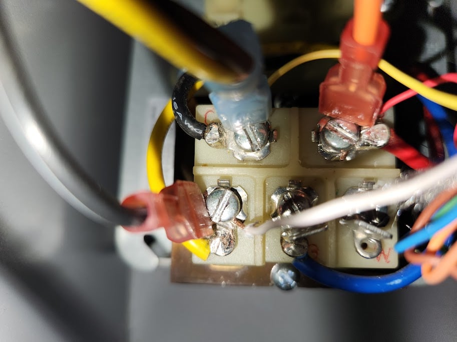
My question: is there a way I can connect the thermostat so that it receives continuous power without being affected by the LWC unit? Here's a photo of the transformer. I'm wired to C and R on the top row, and Y on the left side of the bottom row.
Any help or suggestions are much appreciated! I feel like there has to be a simpler solution here than calling a tech for a house call when I'm perfectly capable of rerouting some wire
Comments
-
YES
Edward Young Retired
After you make that expensive repair and you still have the same problem, What will you check next?
0 -
That @EdTheHeaterMan is being a smart azz again.
Will need more info than a picture of a transformer with 10 or so wires attached.
Can you step back a few feet and let us see where the wires actually go to?Edward Young Retired
After you make that expensive repair and you still have the same problem, What will you check next?
1 -
What is happening is that the LWCO is working as designed -- it cuts power to the boiler when the water is low. Your arrangement, with the 24 VZC transformer on the boiler circuit -- is not at all uncommon, and was just fine when a thermostat was just a thermostat -- a switch. Doesn't work so well when it needs to be a continuously powered widget. You will need to rewire so that it gets its power from somewhere else -- which may be simple or not so simple, depending on how the rest of the system is wired.Br. Jamie, osb
Building superintendent/caretaker, 7200 sq. ft. historic house museum with dependencies in New England0 -
Is this your wiring diagram?

This indicates that you have a float type LWCO. This is simple as @Jamie Hall indicates
I believe you have a probe type LWCO, then this is not your wiring diagram. And there is a not so simple way to do it. Those systems seem to break the R from the transformer to the R on the thermostat. It can be done a few ways. need your actual diagram to show you.
Edward Young Retired
After you make that expensive repair and you still have the same problem, What will you check next?
0 -
Thanks to you both! I've attached a larger pic of the inside here. The LWC is Cyclegard cg450-1560. I looked at the manual and it appears to have a couple of wiring diagrams inside - is there a way to know which is the 'truth'?

I've got easy enough access so I can provide more pics (and get in some exercise running up and down the stairs!) if necessary.
Thanks again for the help, learning a lot about HVAC and this house in the process.
0 -
And here's the page in the book with the circuit diagram for probe-type:

0 -
I believe this is your answer
 The transformer 120VAC side loses power whenever the LWCO is engaged in a low water event. There is nothing you can do to prevent that. So you power the thermostat with a separate transformer and operate an isolation relay to make the circuit between R and Y on the boiler transformer wiring block. Then the LWCO will have no effect on the thermostat operation.
 Edward Young Retired
After you make that expensive repair and you still have the same problem, What will you check next?
0 -
If you read up on the Cycle Guard LWCO, you will see that it shuts down the fire every 15 minutes and pauses to make sure your water probe is not being fooled by foam in the boiler.
Your Low water condition may not really exist.
As you know this kills all power to the boiler, including the vent damper.
So after this shut down, it powers up, the vent damper has to close from where is was stalled, then open again before firing....a lot of needless cycling for that motor.
The time clock for the Cyclegard runs constantly. So with a call for heat it may be in one of it's "Check the water level" moments and then time delay for powering up the boiler.
Or boiler may fire for a few minutes and here come the water check.
In the case I had, the tstat then had an added time delay so boiler was off almost as much as on.
The tstat had to then run on batteries until powered back on.
And for me this was a large system with a lot of piping, the air vents might just start closing then we get the cycle check.
I change the Cycleguard out to a standard LWCO probe.
This took care of all the issues.0 -
This transformer is all you need. https://www.supplyhouse.com/Packard-PF42420-Foot-Mounted-120-208-240V-Primary-24V-Secondary-20VA-Transformer
This is s very popular realy for your situation https://www.supplyhouse.com/Functional-Devices-RIBU1C-Enclosed-Pilot-Relay-10-Amp-SPDT-w-10-30-Vac-DC-120-Vac-CoilOR USE THIS
This is a combination of both the transformer and the realy that will mount on a standard 4X4 electric box for easy wiring.
https://www.supplyhouse.com/White-Rodgers-90-113-Fan-Control-Center-120-VAC-Primary-24-VAC-Secondary-SPDT-Relay
About $30 either way.
Edward Young Retired
After you make that expensive repair and you still have the same problem, What will you check next?
 1
1 -
Recent Peerless residential boilers come with a 120 volt Cyclegard that yes, shuts everything down every X minutes, whether the boiler is running or not, to test the water level.
People here tend to hate them, but I find it a very safe low water cutoff.
I would do what Ed says and get a transformer to power your thermostat and let the boiler do its thing.
You can wire up the Cyclegard to synchronize its testing with the call for heat, it is described in the manualNJ Steam Homeowner.
See my sight glass boiler videos: https://bit.ly/3sZW1el0 -
Thank you all for the additional info, very insightful. On the Cyclegard topic - it sounds like the testing on call for heat would be a bit more efficient, but in the current setup would likely result in the system never turning on (call for heat arrives > Cyclegard kicks in, turning off system > thermostat reboots > thermostat calls for heat > ... repeat). That might be something to look into after I have the thermostat isolated.
On that note - it looks like the fan control transformer/relay @EdTheHeaterMan posted is similar if not identical to the one installed in the system now. It makes sense, but gives me a sensible chuckle that I'll have two of the same device.
I'm reading the very helpful schematic correctly, I'm mounting a new junction box and wiring the new Fan Control into line current.
Then I'm jumping R-R and Y-Y between the terminals on the two fan controls (existing and new). Thermostat will then get its R and C from the new fan control. If that's all correct, my only question is where thermostat W goes.
Thanks again for all the help, I feel like I'm 90% of the way there. Looks like I have a project this weekend!0 -
I'm not sure your statement in bold above is exactly correct. Here is the wiring diagram from the Fan Center control.tucker973 said:Thank you all for the additional info, very insightful.
I'm reading the very helpful schematic correctly, I'm mounting a new junction box and wiring the new Fan Control into line current.
Then I'm jumping R-R and Y-Y between the terminals on the two fan controls (existing and new). Thermostat will then get its R and C from the new fan control. If that's all correct, my only question is where thermostat W goes.
Thanks again for all the help, I feel like I'm 90% of the way there. Looks like I have a project this weekend!
Pay attention to the Black and Red at the top left. Those wires are the ones that connect to Y and R on the existing transformer.
Pay attention to this section of my previous diagram with the isolation relay.
In the red circle of the original existing diagram is where you would place a 2 wire thermostat (Supplied by others). In the Red circle on the modified isolation relay is where you place the Black (Common) and Red (Normal Open contact) so to make it simple put the Red on R of the existing transformer and place Black on the Y of the existing transformer. (of course this assumes that you have removed the three thermostat wires that are already there form your thermostat). That is the isolation part of the existing system transformer
Now the thermostat side of the isolation relay. Notice the the relay coil is shown with C and G. Look at where they are located on the actual Fan Center.
Now referring to the Isolation relay diagram above, You will connect the Thermostat R to R on the transformer, and the thermostat C to the C on the transformer. As you correctly stated. Your question about where to put the thermostat white wire is simple. Place W on the thermostat to G on the transformer.
This will offer you a complete path from R transformer to > R thermostat to > W thermostat to > G relay coil to > C relay coil wire ending > at the return path of C on the transformer for a complete circuit.
From source.........to switch........to load......... to return path....... to source
From transformer to thermostat to relay coil to return path back to the transformer.
I hope this clears up any confusion so you don't let the smoke out of any transformers.
I also have a trick that I use when installing transformers so they don't burn up. Place a 3 amp automotive fuse on the R terminal of the new transformer then connect the Red wires to the other side of the fuse. Easy to make a pigtail with a solderless push on terminal from your automotive electrical tool box ..... like this
Respectfully
MR. Ed
Edward Young Retired
After you make that expensive repair and you still have the same problem, What will you check next?
 1
1 -
Thanks for your patience, @EdTheHeaterMan I really appreciate it.
I love the auto fuse tip - I'll be using that in the future for sure!
Editing this post, because I have the part in hand now and see I was wildly off with my diagram and understanding. I'm going look at things closer in a bit and post an update.
Thanks again, this advice has been invaluable!0 -
OK, I was misunderstanding the construction of the part, so having it in hand and looking at the manufacturer diagram helped. Here's a crude diagram that shows my understanding:
Back of new control:
-Red wire to R on existing boiler control \___two sides of relay, normally open so no call for heat
-Black wire to Y on existing boiler control /
Front of new control:
-R terminal to thermostat R \______these power thermostat independent from boiler
-C terminal to thermostat C /
-G terminal to thermostat W _______this calls for heat, closing relay and making R/Y conn on boiler
Brown wire (N.C. side) on back of new control is unused.
I think I've got it now!
 1
1 -
You understand perfectly
Edward Young Retired
After you make that expensive repair and you still have the same problem, What will you check next?
1 -
I know everyone has waited with extreme anticipation for any updates on my setup! I got the part and was ready to go, but ultimately was too apprehensive about messing with the existing wiring to mount the part safely.
After time went by and I was stewing about the situation, I stumbled on a kit for another smart thermostat manufacturer that would work perfect for this use case. In fact, someone in the reviews on Amazon was also using it with an ecobee.
So, here's what I did, from the boiler back:
Ran the relay Red and White to R/Y on boiler. This is the only connection inside the boiler case.
I connected the thermostat side of the relay as follows (pic from testing phase):
Brown > Yellow (C) & one of 40v wall transformer leads
Orange > White (W1)
I also connected on the thermostat wire:
Red (Rh) > second 40v wall transformer lead
I pulled all the wire into a spare 2 gang plastic box. For maintenance purposes, I connected the length of T wire that runs to the boiler with disconnects, crimped off the other connections and snugged the relay inside.
Mounted the box to the outside of the boiler with velcro command strips to remove it for maintenance, plugged the wall transformer into a nearby outlet, and put a plastic cover on the box after I took this pic.
Thanks to everyone for the help, especially @EdTheHeaterMan for the patient followups. I'm glad I stumbled on this kit. Hopefully someday this thread will help someone with a similar question!0 -
This https://www.supplyhouse.com/Venstar-ACC0436-Two-Wire-Kit is a different version of this https://www.supplyhouse.com/White-Rodgers-90-113-Fan-Control-Center-120-VAC-Primary-24-VAC-Secondary-SPDT-Relay
Same difference. as long as you are comfortable with your work. thanks for the updateEdward Young Retired
After you make that expensive repair and you still have the same problem, What will you check next?
0 -
@tucker973 what was the kit you purchased? The link just goes back to this post. Thanks. I have the same situation.0


Categories
- All Categories
- 87.7K THE MAIN WALL
- 3.3K A-C, Heat Pumps & Refrigeration
- 59 Biomass
- 431 Carbon Monoxide Awareness
- 127 Chimneys & Flues
- 2.2K Domestic Hot Water
- 5.9K Gas Heating
- 121 Geothermal
- 170 Indoor-Air Quality
- 3.8K Oil Heating
- 79 Pipe Deterioration
- 1K Plumbing
- 6.6K Radiant Heating
- 396 Solar
- 16K Strictly Steam
- 3.5K Thermostats and Controls
- 56 Water Quality
- 51 Industry Classes
- 51 Job Opportunities
- 17 Recall Announcements