Which is the C (common) terminal on a Honeywell Aquastat L8148E?


Comments
-
This YouTube video says that the L2 terminal on the bottom right is the common terminal:
 https://www.youtube.com/watch?v=BZJ2tch3_oc
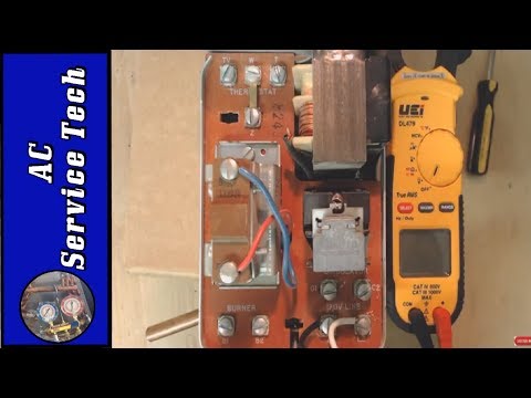
Photo of my panel:
 0
0 -
L1 and L2 should be 120 VAC power. It's unlikely that either one is a common for the transformer output. It is remotely possible that one of the two terminals on the aquastat dial is common -- that is, directly connected to one side of the transformer output -- but to verify that you need a multimeter.
There is no labelled common terminal because, until you decided to swap out your thermostat with a Nest, one wasn't needed.Br. Jamie, osb
Building superintendent/caretaker, 7200 sq. ft. historic house museum with dependencies in New England 2
2 -
Hello @erikengquist,
L2 is on the 120 VAC side and that is definitely not what you are looking for. Depending what the system includes the Z terminal may be what you need. There are other scenarios if the system has R882C zone relays. See manual.
As to not put your Aquastat's transformer in jeopardy I would use a separate transformer for the NEST and an additional relay if needed.
National - U.S. Gas Boiler 45+ Years Old
Steam 300 SQ. FT. - EDR 347
One Pipe System0 -
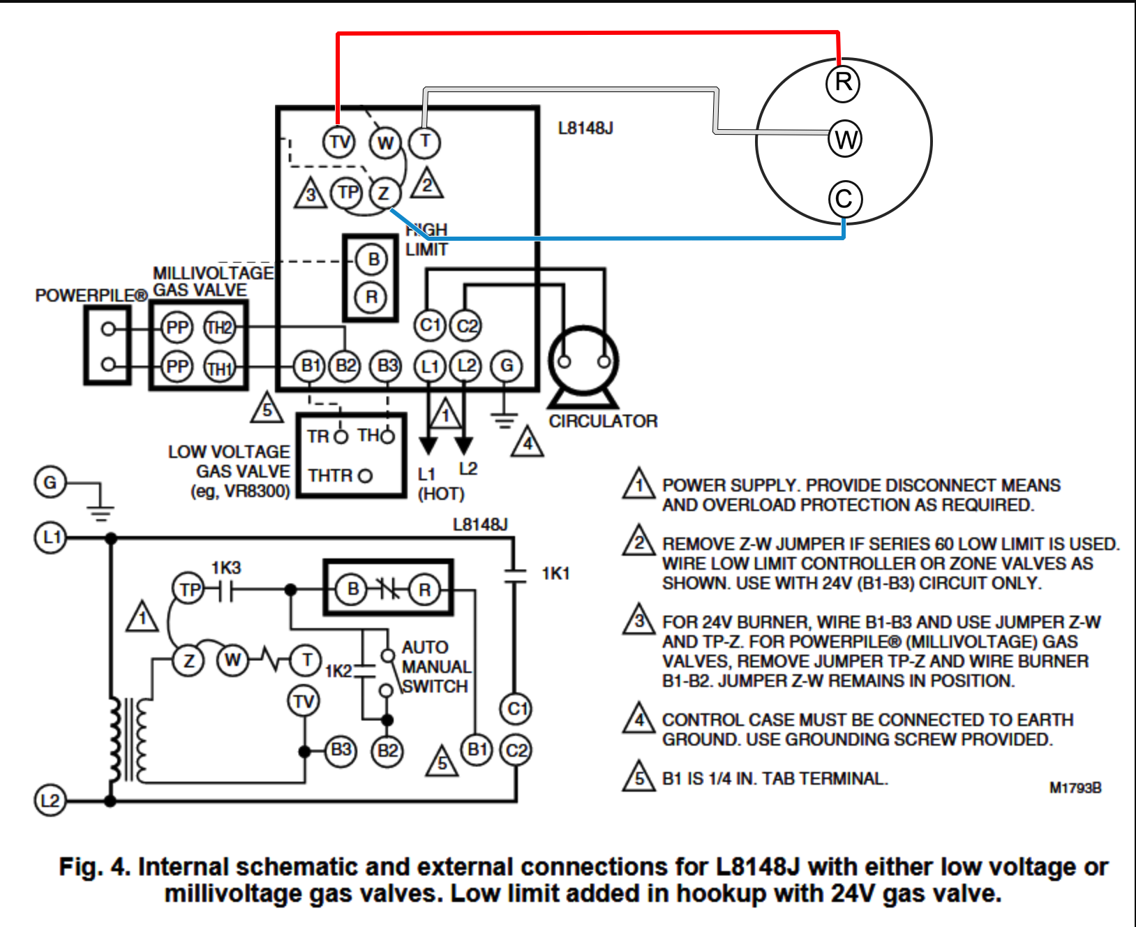
TV on L8184E control = R on the NEST
Z on L8184E control = C on the NEST
T on L8184E control = W on the NEST
Leave the jumper between Z and W on L8184E control
Must use the terminals in the proper order so you don't get a SHORT @109A_5
And you do not need the NEST power connector accessory
Wire the thermostat like this.
Don't worry about this information @109A_5 said "As to not put your Aquastat's transformer in jeopardy I would use a separate transformer for the NEST and an additional relay if needed.. That transformer in your L8148E can handle up to 2 zone valves... more than enough power to accommodate a thermostat.
Edward Young Retired
After you make that expensive repair and you still have the same problem, What will you check next?

 2
2 -
What are you trying to accomplish?0
-
This:pedmec said:What are you trying to accomplish?
erikengquist said:I need to install a Nest Power Connector to my Honeywell Aquastat Relay Type L8148E control board on my heat-only system (hot water boiler). I have the control board manual, which does not identify the common terminal. My best guess is it's where the blue wire connects to a terminal marked "B." The two low-voltage wires from the thermostat (red and white) are connected at the top. The common terminal is somewhere else. But where?
Edward Young Retired
After you make that expensive repair and you still have the same problem, What will you check next?
0 -
@EdTheHeaterMan
I don't agree. B2 and Tv look like the common to me. The high limit to B1 is breaking the 24 volt hot 2
2 -
or
remove jumper z-w
add jumper to t-tv
connect z at aquastat to r on thermostat
connect w at aquastat to w at thermostat
connect c on thermostat to either t or tv on aquastat
1 -
Show me how to wire the W wire on the Nest if you are using the B2 & TV s the common? I cant see it!EBEBRATT-Ed said:@EdTheHeaterMan
I don't agree. B2 and Tv look like the common to me. The high limit to B1 is breaking the 24 volt hot
The thermostat needs to complete the circuit between T and TV to turn on the Relay that Makes and Breaks the voltage to B1. and also to make and break 120V. to C1
My original diagram will work with no rewiring of jumpers and the like. Basic and simple.
The OP is not a technician like all of us. I gave them the easiest way to get the job done. Someone needs to tell me why the left diagram will not work. If it can't be done that way then lets all take a basic control wiring course.Edward Young Retired
After you make that expensive repair and you still have the same problem, What will you check next?

 2
2 -
Is it really better to tell a DYI homeowner that they need to rewire the jumpers in the control? Especially when you say "your recommended wiring diagram probably does get the job done". and I will add to this statement "your recommended wiring diagram probably does get the job done with the least amount of effort"MikeAmann said:Without stepping on @pedmec 's toes, let me take a stab at this.
And if I get this all wrong, then we can have Erin delete the whole thing.
@EdTheHeaterMan , your recommended wiring diagram probably does get the job done, but I think @pedmec has the better way. EDIT: Better How? requires relocating jumper wires. Is that really better? especially when you don't do this for a living
The line in question is the 24v from the transformer, through a thermostat contact, powering the 1K relay coil, and back to the other end of the transformer.
The Common in an AC circuit is the point of zero volts, neutral, usually the white wire, and could also be tied to ground. In the diagram above, that would be TV and B2. So let's make that the common, or "C" wire.
By removing the jumper from Z to W and relocating it from T to TV, you have created the place that ties directly to COMMON and will always be Zero volts. Connect W to W on the NEST, and power the NEST with 24v by connecting R to Z on the aquastat.
SIMPLE.
Still waiting for someone to tell me "IT WONT WORK" or "IT IS WRONG". And show the error! The incomplete circuit, the Short Circuit or something that will cause a failure to operate as intended.
Edward Young Retired
After you make that expensive repair and you still have the same problem, What will you check next?
0 -
this is all that is needed
TV on L8184E control = R on the NEST
Z on L8184E control = C on the NEST
T on L8184E control = W on the NEST
Don't change any jumper between Z and W on L8184E control. Leave it where it is.
Must I remind everyone that Electric is colorblind and it can't read either. This works for the control that @erikengquist shows in the picture. L8148E. It does not work for other controls like the L8148AEdward Young Retired
After you make that expensive repair and you still have the same problem, What will you check next?

 3
3 -
B2 is neutral on the line volt side. There's a reason Honeywell puts a cardboard divider between the line and low volt terminals.
W/Z is Common on the low volt side.
You will sometimes see diagrams using W for switching through the thermostats or completing the circuit on zone valves, but not on thermostats that require 24v power.
2 -
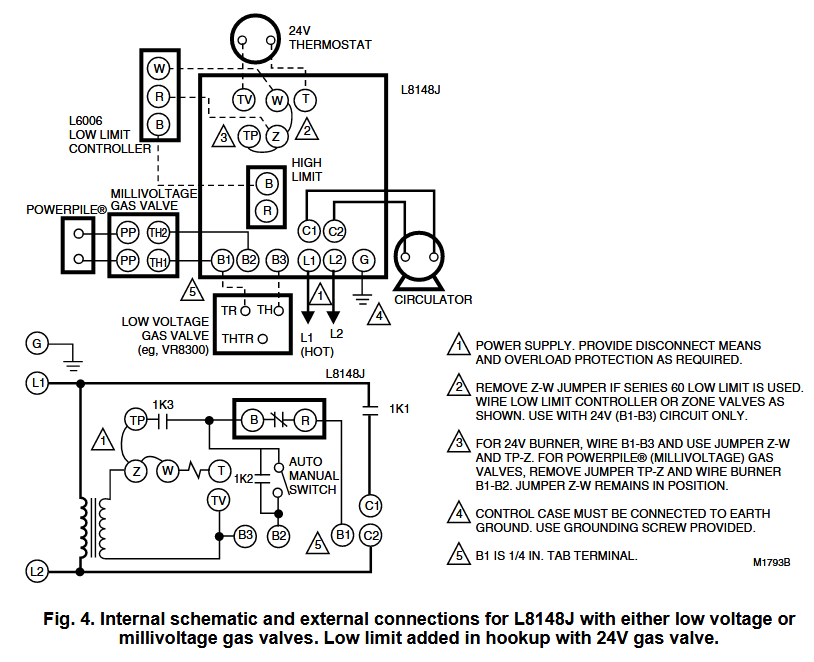
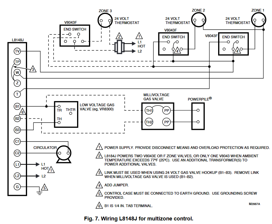
The L8148 comes in three versions. The L8148A controls line-voltage burner circuits; the L8148E,J control low-voltage burner circuits; the L8148J controls millivoltage burner circuits. All models controlHVACNUT said:B2 is neutral on the line volt side. There's a reason Honeywell puts a cardboard divider between the line and low volt terminals.
W/Z is Common on the low volt side.
You will sometimes see diagrams using W for switching through the thermostats or completing the circuit on zone valves, but not on thermostats that require 24v power.
line-voltage circulator circuits. L8148A,E,J have provisions for adding low-limit controllers; L8148E,J can power valves in multizone systems.
And this is where the confusion might arise. B2 is common on the line voltage models. However B2 on the low voltage model may not necessarily be common on the E and is not part of the low voltage circuit in the J model. It is isolated for millivoltage use of B1 and B2 thru the limit.
In order to keep it simple for the layman (original poster) I believe it is irresponsible for professionals to have this debate on his discussion. If we can't agree with a consensus, how is the non professional supposed to be helped by HeatingHelp.com?
If I were to be incorrect, I would admit it so as not to have the person asking for help, do something that will damage the control or thermostat they are trying to connect to the heating boiler.
Just an opinion.
Oh, By the way, I looked up an old record in my business files, it seams that I did exactly that wiring diagram for one of my mechanics in order to install a Nest thermostat. At the time I was a NEST PRO and getting referrals from NEST to professionally install their products. This added a few years to the warranty and gave me new customer leads for servicing their heating equipment.
Edward Young Retired
After you make that expensive repair and you still have the same problem, What will you check next?
 3
3 -
All of which, @EdTheHeaterMan , is why I didn't comment at first -- but will now, with a general comment.
Unless one has a wiring diagram of the circuits for a specific make and model of unit, you are to an extent guessing at what is actually connected to what. A truly competent electrician or controls person (or knowledgeable amateur) can make good educated guesses, using the proper test equipment.
There is a related problem with regard to this particular thread -- we are talking about a "common" connection. But common with what? Unless -- again -- you have that wiring diagram, you have no reliable way of being certain that a given terminal is connected directly to a transformer terminal -- making it a common for that transformer -- or is switched, which isn't a common. You also have no way of knowing reliably if that terminal you think is a common is also grounded or bonded to the unit chassis. On the 120 volt power side, you again have no reliable way of knowing which -- if either -- terminal is actually grounded in the unit; it's perfectly possible for both sides to be grounded or bonded if at all at the switchboard, with a separate ground path for the chassis.
Guessing can be fun. It can also be unduly exciting -- or even expensive...Br. Jamie, osb
Building superintendent/caretaker, 7200 sq. ft. historic house museum with dependencies in New England2 -
Go with @EdTheHeaterMan 's hookup, my Nest is wired this way and I have had no problems with it and it's been a couple of years now. I think he's correct in being against rewiring the aquastat for the DIYer. It just opens up the possibility of making a costly mistake and ending up with no heat.3
-
Yes, on 24v burner circuit B2 can be used.EdTheHeaterMan said:B2 is neutral on the line volt side. There's a reason Honeywell puts a cardboard divider between the line and low volt terminals.
The L8148 comes in three versions. The L8148A controls line-voltage burner circuits; the L8148E,J control low-voltage burner circuits; the L8148J controls millivoltage burner circuits. All models control line-voltage circulator circuits. L8148A,E,J have provisions for adding low-limit controllers; L8148E,J can power valves in multizone systems. And this is where the confusion might arise. B2 is common on the line voltage models. However B2 on the low voltage model may not necessarily be common on the E and is not part of the low voltage circuit in the J model. It is isolated for millivoltage use of B1 and B2 thru the limit. In order to keep it simple for the layman (original poster) I believe it is irresponsible for professionals to have this debate on his discussion. If we can't agree with a consensus, how is the non professional supposed to be helped by HeatingHelp.com? If I were to be incorrect, I would admit it so as not to have the person asking for help, do something that will damage the control or thermostat they are trying to connect to the heating boiler. Just an opinion. Oh, By the way, I looked up an old record in my business files, it seams that I did exactly that wiring diagram for one of my mechanics in order to install a Nest thermostat. At the time I was a NEST PRO and getting referrals from NEST to professionally install their products. This added a few years to the warranty and gave me new customer leads for servicing their heating equipment.
W/Z is Common on the low volt side.
You will sometimes see diagrams using W for switching through the thermostats or completing the circuit on zone valves, but not on thermostats that require 24v power.1 -
EdTheHeaterMan--I don't know why everyone is making such a fuss. What you say makes perfect sense and of course correct. But of course, he is installing a Nest Power Connector because he has a two wire sys to the original thermostat. So, he probably would like a diagram of the power connector with the Nest thermo and the aquastat all connected.0
-
I have the exact same question/challenge. I went through all the comments which are great but it does not provide the answer which OP has raised. As suggested by @HomerJSmith -Can someone please share diagram as I am also installing a Nest Power Connector because I have two wire sys to the original thermostat. So, I would like a diagram of the nest power connector with the Nest thermo and the aquastat all connected?0
-
Hi guys, not the same controller, but I have to find a way to get power as well for a Nest thermostat. Here is a pic of my Tv T and W wires. T and W are jumpered. As in...

I am thinking I can tap W for the C wire, and Tv for R, but please advise!
Boiler -> Nest Power Connector -> Thermostat...
Tv -> R -> R
W -> C -> W
W -> W -> W0 -
I haven't thought this thru, but maybe a aux transformer and isolation relay may be the way to go with a Nest power connector.0
-
So after I sent in the above picture and question, I went down to the cellar and traced the thermostat wires, and found a fully functional 24V transformer along the way! The transformer is external and independent of the boiler's, and wired to the 120V line in a junction box. Tracing back from the junction box to the thermostat, only the R and W wires reached it. The two transformer wires were cut and capped in the wall. I think they were being used for a yet earlier thermostat, the rectangular outline of which you can see in the photos. I pulled the transformer wires out of the wall and hooked them up at shown. No power problems, and has been running for a couple of days without issue. This weekend I'm going to run totally new wire up to the transformer and junction box to get rid of this dangerous stuff.HomerJSmith said:I haven't thought this thru, but maybe a aux transformer and isolation relay may be the way to go with a Nest power connector.

0 -
Apologies for the post necromancy, but this thread is the first Google result for "Aquastat Relay L8148e Nest". @EdTheHeaterMan had a great explanation and justification and it worked perfect for me with an Ecobee. Thanks, Ed! Only hitch was that they send the primary R wire to RC instead of RH, but that's an Ecobee thing and not an Aquastat thing.
I would add one other piece that the DIYer might need spelled out. You do not need to kill the breaker, just shutting off the boiler will do it for you. HOWEVER: if you hang your trouble light next to the switch and then accidently bump the power on while adjusting the light, you will feel some current while twisting some wires in there. Source: my fingies.1 -
Hello. I have a L8148J which has an additional terminal Tp that is jumpered to W and Z terminals. Would I still connect the C on my Nest to the Z terminal on the Aquastat as suggested on this thread?
 0
0 -
I would say it will be Z or TV depending on how the rest of the system is wired.
 National - U.S. Gas Boiler 45+ Years Old
Steam 300 SQ. FT. - EDR 347
One Pipe System0 -
TV = R
T = W
Z = C
Edward Young Retired
After you make that expensive repair and you still have the same problem, What will you check next?
0 -
Ed is 100% correct
TV=R
T=W
Z=C
0


Categories
- All Categories
- 87.7K THE MAIN WALL
- 3.3K A-C, Heat Pumps & Refrigeration
- 59 Biomass
- 430 Carbon Monoxide Awareness
- 129 Chimneys & Flues
- 2.2K Domestic Hot Water
- 5.9K Gas Heating
- 122 Geothermal
- 170 Indoor-Air Quality
- 3.8K Oil Heating
- 79 Pipe Deterioration
- 1.1K Plumbing
- 6.6K Radiant Heating
- 396 Solar
- 16K Strictly Steam
- 3.5K Thermostats and Controls
- 56 Water Quality
- 51 Industry Classes
- 51 Job Opportunities
- 17 Recall Announcements