Welcome! Here are the website rules, as well as some tips for using this forum.
Need to contact us? Visit https://heatinghelp.com/contact-us/.
Click here to Find a Contractor in your area.
If our community has helped you, please consider making a contribution to support this website. Thanks!
Principal Amy's School Steam System Repairs-Pictures & Blue Prints--Revisit this Fall
Options

JUGHNE
Member Posts: 11,604
Two working trips were made to the school, (300 miles round trip).
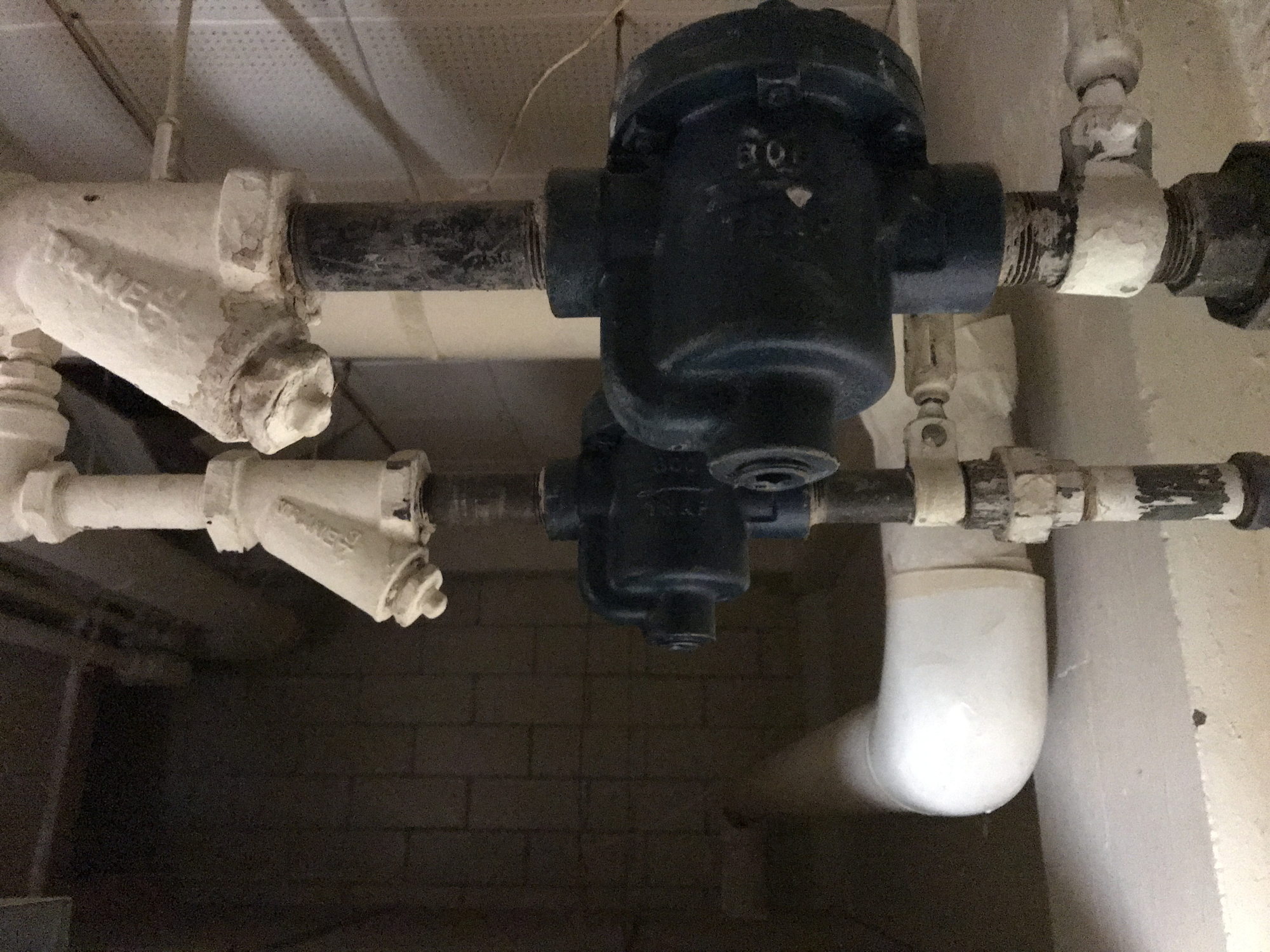
4 EOM F&T's were replaced/rebuilt. About 25 thermostatic traps changed/repaired.
I have learned that bucket traps do not do well as F&T's for a heating system.
These were hiding above a ceiling, 2 generations of maint men did not know they were there. They may not have seen daylight since installation years ago.
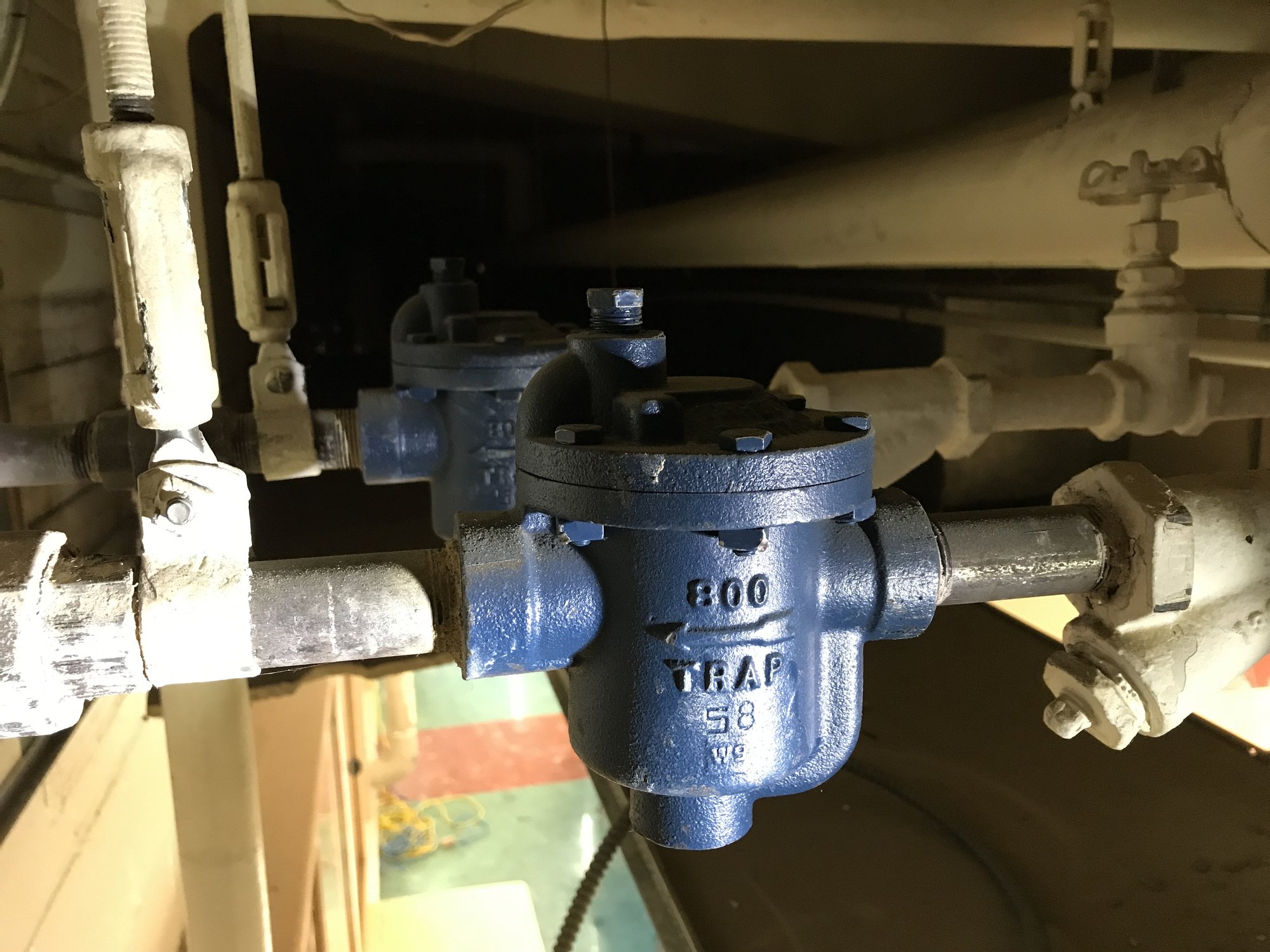
These 3 new F&T's were installed.
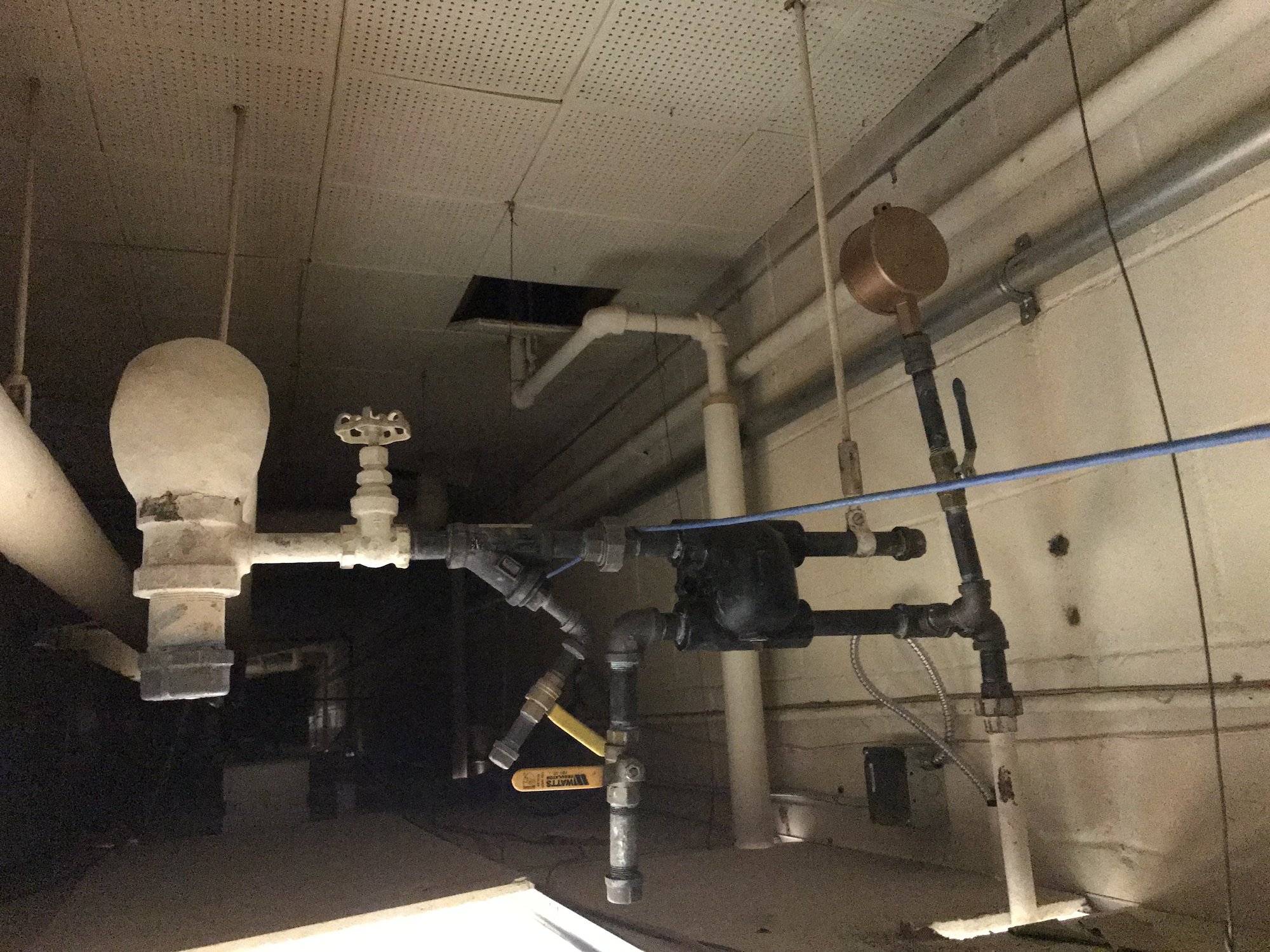
Strainer with 3/8 " blow down valves, test ports on F&T outlet, G-2 air vent on outlet with valve to isolate G2 if it ever blows steam/water.
Maint man was shown how to blow down strainers and open outlet test ports to assure that they are not blowing steam.
The 2 outlets are connected to a common dry return, so if steam shows in one it would show in the other test port. By closing one gate valve you can figure out which F&T has failed.
The logic/reason for adding the G2 air vents to the "dry return" side of the F&T's is that in this installation the return line starts about 12" above the floor and slopes down towards the transfer pump. But that run is over 150' long and not visible as being boxed in.
Then part of it is under floor to the transfer pit, this was replaced sometime in the past and may or may not be "dry return".
I feel these vents added in 5 places will help the return piping breath adding in steam delivery speed and water return.
In theory the vent could be replaced with an open pipe, but things do happen to traps over the years. And the isolation valve under the G2 is redundant....if needed.
You know the transfer cond pump has passed steam thru it's vent for a long time, when there is a permanent collection bucket, with hose to floor drain, hanging from the U turn down that is 6' above the floor.


7
Comments
-
Nice work.1
-
And more...changed the face plates on these 2 Hoffmans.
Another EOM, not room for air venting, just strainer.
Hanging heater for addition of the 70's, (building is 1951).
Heater was taken down and cleaned, as it is in the fish fry work room.
The over and under piping was done for the addition doorway.
You can see the elevation of the "dry return" that travels that 150+ feet to the pump.


All dirt legs in the building with a lot of down feed steam supplies, were opened and cleaned, not as bad as you might imagine after 70 years of steaming.1 -
Then this made me wonder if there was a discussion in 1950 between 2 steamfitters.
The garden level basement has convectors on East wall and West wall.
If you analyze the effectiveness of the drip traps on the downfeed steam supplies you can see a difference of opinion perhaps from side to side installation.


In the first picture, the drip trap would at best pass air on start and then the steam would have to push the condensate thru the convector to the outlet trap.
The steam drop is about 14' of 3/4" pipe, so that is all the condensate it would have to handle.
In the second picture, the drip trap might pass some condensate but the run out to the convector is running a little up hill towards the unit.
Same steam drop dimensions.
Notice the inline TRV's. They were angled a little to prevent the supply piping heat from affecting the thermostat....but they would close prematurely.
And then especially when a little "dog house" was put over them for protection from PE activities.
We are leaving the tstat controls off of these units to see how they heat or not.
This is the largest room in the school and has been the coldest.
And as you look at the convectors, why do these not put out more heat??
Finally "Mr. Obvious" slapped me on the side of the head....how does the air get into the bottom??....when you see something nicely boxed in and painted what could be wrong with that. (box in of return piping was probably done during asbestos abatement/encapsulation work of 1980's?)
So 24" X 6", heavy drop in floor return air grills, will be cut in below each convector for air inlet. Two of the units had to be removed and reinstalled to cut the top of the box for openings.
The sensor for the thermostat is mounted on a pillar in the open area.
Previously there was no tstat. Just time clock from 4 AM to 8 PM calling for heat.
Manual shut off during the day if overheating occurred.
The third picture is what we would consider proper drip trap piping.
Although the supply is capped as this was a front door entry unit that froze up some years ago.
Note: on another down feed job that someone had replaced traps for the entire system, a trap like this was neglected as they assumed that without a rad connected did not need the drip trap renewed. Those orphans still had 1932 elements inside, doubtful if they were closing.....so steam into the dry returns on that job.0 -
What is going on with the 2 layers of ceilings? It looks like there is a 1950's ceiling with steam piping below it that doesn't really look like it was intended to be exposed but it also loos like it has been there since the 50's.

 2
2 -


Prints for the original building of 1950.
It seemed to show options for steam systems:
Vacuum pump option with lift F&T's---no evidence of them ever there.
Steam supply to the Nun's Convent from school----not done, that building has a separate heat pump system today.
Steam supply UG across parking lot to church. Was installed as shown but later a hot water boiler in school supplied heat to church thru steam pipes underground.
That HW boiler died last Feb and was replaced with 2 Lochinvars in the school boiler room.
 1
1 -
was this the job at 7 psi ?
what is it at now?known to beat dead horses0 -
Matt, yes 2 ceilings. The piping was exposed as evidenced by white paint on everything up there.
Central AC was added in 60-70's, (looking at outside units).
It's ductwork parallels the steam piping above the new 2 X 4 grid ceiling.
My school was in the basement of a 1911church, 3" bare piping mains were exposed...our only source of heat. We did insulate a few years ago.
That school area is now the "social hall" as this school has.
Funeral dinners and of course Friday fish fry's.0 -
Neilc, yes it was about 7 PSI. This happens when a large professional company sets up a boiler or adjusts anything. They must be right as they come a long ways to be there and get maybe 5 bills to just show up.

It now runs from 1 up to 3.25 PSI.
The next visit next fall may include a 0-4 PSI vaporstat.
I don't change something like this when it is 3 hours away,
and I can not monitor the heating situation without being there for a few hours in cold weather,
It was in the 60's this trip.
1 -
Today on the bench at home, one of the bucket traps was opened and there was no evident damage, hard to tell about the seat and sealing ball.
However the ITT F&T was opened and the float was loose in the housing and the seat was broken off. So this would pass steam in addition to the 2 buckets that were not primed.

The date code on the F&T was J49 which is Sept. of 1994.
From the looks of the piping (a little hacked) on the 2 buckets and this F&T it looks like the same installer.
So almost 25+ years or so.1 -
I hope you didn't feel trapped when you were working there!
Edward Young Retired
After you make that expensive repair and you still have the same problem, What will you check next?
0 -
Well Ed, more trap pictures.......
There were 3 Trane "B1" traps. The rest were Hoffman's.
I inquired about B&J cage units and was told there were 3 possibilities and so the old would have to removed to verify replacement.
I just replaced these with new B&J traps.
As the caps were removed the lower plunger was lying inside the body.
The top left trap had 2 parts lying in the bottom of the body.
The one good thing I can say about these Tranes is that the brass spud had a 3/8" square opening inside for install/removal.
I think the impact is what caused the lower plunger to come off.
But the one with the extra plunger may have been from a previous change??0 -
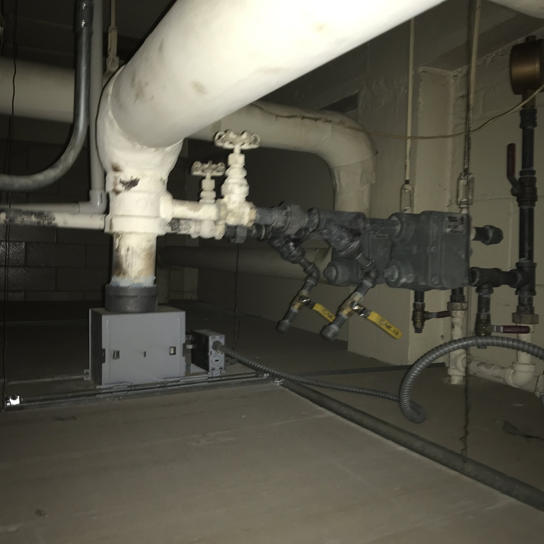
Questions on some feeder components,
One of these is at the feeder pump and then another on the feeder line at the HL where the water is pumped.
1" in and out.
Are they check valves and/or restrictive flow devices?
The feeder tank is fed by a condensate transfer pump in a pit, with a check valve in that pump output line.

0 -
must be a flow restrictor.1
-
Since the last trip at the end of Feb, 2022, the OAT stayed pretty mild.
Then last week it finally dipped into the teens-20's.
Phone call said 2nd floor was cold.
The basement/social hall garden level radiation was working better with the air inlet on the bottom of the convectors being opened by adding grills in the box under them .
The temp sensor is in that area, shutting down boiler early before reaching temp on 2nd floor.
Did some control changes down there. Set all 2nd floor TRV's to max and then Monday AM I could see windows open on 2nd floor.....good sign in this case. 6 classrooms up there.
6 teachers learned how to adjust their temp down.....5 women and 1 man....you all know the scenario.
Wallie questions:
What is the preferred TRV for steam convectors, 1"angle valve with remote cap tube tstat?
The building currently has AMMARK 76N remote tstats. They don't seem to respond well.
Then cleaned the M&M 157 LWCO/feeder pump control, it has the three try cocks and the sight glass all on one CI unit. All 5 of the ports into the chamber were plugged or nearly so.
The chamber buildup was typical for the age.
But when flushing it out there were 2 brass balls, about 3/8" OD in the blow down bucket.
What are these from?
This boiler was built in 1993 so the 157 switches are original mercury type.
Has anyone ever tried to adjust these? Or leave them alone....replace that float/switch assembly?
I could use about another 1" of water level, there is little differential between pump on and off.
Sometimes as it switches the pump on the LWCO is activated and burner shuts down and fires back up almost immediately.
There seems to be some "slop" in the pump HG switch mechanism.
Although it still functioned, I did change the original 1993 Hydrolevel 550P manual reset LWCO & probe.
The feeder tank fill valve was cleaned and new inlet screen installed.
Gordo's infamous sight glass blow down valve was added.
The boiler is a 1993 PB 211A-07, 12 burners, 1.2 million, 29.3 HP. 1951 building.
It does now run at 2.75 PSI with a fair amount of short cycling on a 30 degree day.
After spending several days there, last spring and this fall, I have come to the conclusion that in 1993-95
the F&T's, some traps, the boiler and the TRV's were installed and never touched until now.
So again leave the job, 150 miles away, and mild weather again.
As Douglas Mac said "I shall return".
 0
0 -
McDonnell Miller used to make a head/switch assembly for the 150 that had more differential. Don't know if it is still available now that they don't have mercury switches.
I think they say "don't adjust switches" but I have and I am sure many others have done that as well. Are they using the 150 as a low water cutoff as well. I have found it works better to be used for pump control only and add a sep control for low water protection.
Don't know about the brass balls1 -
The replacement head for this is right at $900 at supply house com.
So it may be worth the attempt at adjustment.
This is also the primary LWCO and will sometimes cut burner out as pump comes on.
Talking to a rep at a supply house, we thought those balls might be check valves in the event the sight glass was broken. Also a small star washer that looks like a push in holder for the balls.
I have read about this safety feature but did they have the check valve feature in sight glass units in 1995?0 -
Never herd about check valves for sight glasses. It might be cheaper to add a sep LWCO for low water protection and just use the 150 for pump control. I think that's your best bet.
Then the 150 can cycle the pump as it wants without shutting the burner down. The MM parts are outrageous.
If you buy a new head assy they make a 150S (standard) or a 150S-MD (maximum differential).
I looked and unfortunately you cannot retrofit the new snap action switches into the older controls (of course they wouldn't want you to do that when they can sell a new control)
I have always been less than satisfied with the 150. It always works better when the 150 only runs the pump and then use an additional control for LWCO1 -
Thanks for the reply.
I recall reading about some sight glass assembly's that have a feature to close off the ports if the glass breaks and there is a sudden rush of water out of the broken glass.
I will have to go back and try to adjust that switch.
I do have a MM150s on hand and will take it along if things go really south with the attempt.
Existing control is 27 years old, so it has done it job.
0


Categories
- All Categories
- 87.7K THE MAIN WALL
- 3.3K A-C, Heat Pumps & Refrigeration
- 59 Biomass
- 430 Carbon Monoxide Awareness
- 128 Chimneys & Flues
- 2.2K Domestic Hot Water
- 5.9K Gas Heating
- 121 Geothermal
- 170 Indoor-Air Quality
- 3.8K Oil Heating
- 79 Pipe Deterioration
- 1.1K Plumbing
- 6.6K Radiant Heating
- 396 Solar
- 16K Strictly Steam
- 3.5K Thermostats and Controls
- 56 Water Quality
- 51 Industry Classes
- 51 Job Opportunities
- 17 Recall Announcements