Welcome! Here are the website rules, as well as some tips for using this forum.
Need to contact us? Visit https://heatinghelp.com/contact-us/.
Click here to Find a Contractor in your area.
If our community has helped you, please consider making a contribution to support this website. Thanks!
Powering Nest Thermostat from different power source
Options

Ron Jr._3
Member Posts: 605
Hypothetical question. If you have a Nest controlling central AC and a zone for heat at a boiler .......
Can you connect the C terminal in the Nest to a relay with a common at the boiler ? Meaning ..... RH , W and C of the Nest would be powered by the zone relay, like a Taco SR501 . R , G and Y would be connected to the AC equipment.
Have a job where theres one unused wire from the thermostat to the boiler. No extra wire to the air handler and no wire connected to C of the current thermostat.
0
Comments
-
No, "C" has to come from the transformer that's powering "R".
Bob Boan
You can choose to do what you want, but you cannot choose the consequences.1 -
Thanks. Makes my job a bit more difficult ...
 0
0 -
If either the boiler or a/c are modulating equipment, I'd get rid of the Nest. What it does conflicts with the logic of modulating equipment.Bob Boan
You can choose to do what you want, but you cannot choose the consequences.0 -
I have a similar issue. My system has all thermostats going to a Taco Zone Valve control (VZC 404), these intern send signal to one SR 504 to control the circulations (see pictures).


I want to replace one thermostat with a NEST T3007ES thermostat. If I understand all of the comments the NEST needs a third wire ( I have) . I don't see a "common" on the thermostat terminals on the VSC 404. Based on other comments it appears that you need the three wires all connected to the same terminal. I did purchase a separate relay that I can use to power the NEST (see picture) . My question is, would the wiring I propose work?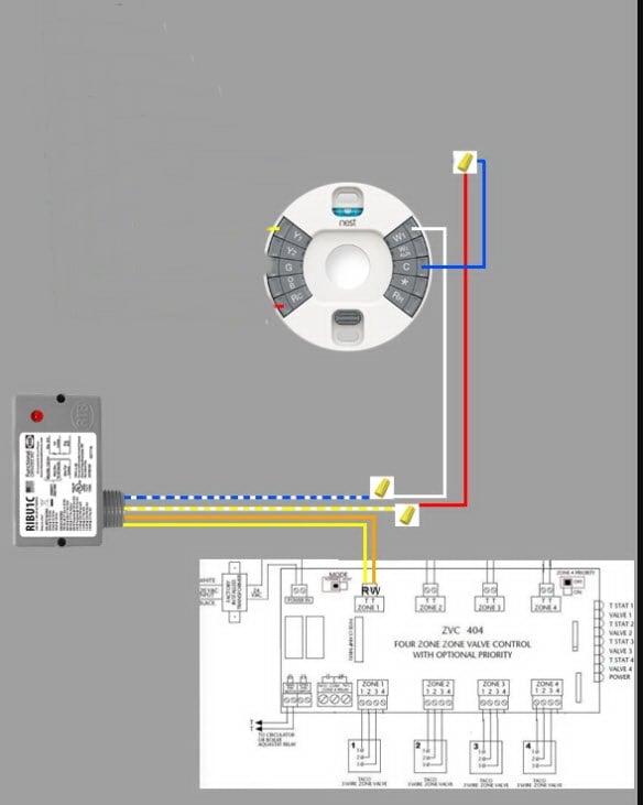
UPDATE: In thinking more about this configuration, I don't think it will work. Originally the diagram had wires comming from an cooling unit that supplied power to the thermostat through the Rc terminal. I don't have that.
Somehow I have to connect the relay to the 120v of the relay and supply isolated power to the C terminal while still switching from the R and W thermostat terminals on the ZC board.1 -
Ron that should work, the Nest has never given me trouble when powering Rc and Rh from two different sources.
I’ve never seen a rule that says C must be on the cooling side1 -
From a Nest manual.GW said:Ron that should work, the Nest has never given me trouble when powering Rc and Rh from two different sources.
I’ve never seen a rule that says C must be on the cooling side
Important Note: In dual transformer installations (installations with both Rc and Rh wires) it's important to note
that different wires attached to the thermostat will use different power sources. The Rc wire will provide power
to the Y1, Y2, G, and O/B terminals. The Rc wire will also charge the thermostat using the C terminal. The Rh
wire will provide power to W1, W2/AUX, and Star connectors. Never connect wires from dual transformer
systems to connectors from the opposite transformer.
Single pipe 392sqft system with an EG-40 rated for 325sqft and it's silent and balanced at all times.
1 -
@MrWizard3 the old Taco ZVC404 does have a common connection. You would bring your common wire from the Nest down to the zone valve #1 terminal on the ZVC controller. So if the Nest is on zone #1 would bring the common wire down to the zone #1 terminal on the zvc. If on zone 2 down to the zone #2 number 1 terminal and so on. We reached out the Nest and if you also pre-charge the Nest t-stat you should have an issues. If you still do you can always place a 220ohm 5 watts resistor ( also what Nests suggests) between the W-C terminals as show on the newer ZVC designs.0
-
Thanks everyone. I'll give the suggestions a try an post an update.1
-
Thanks again for all the helpful tips. I wound up running a new thermostat wire to the air handler.
FYI , the "pro" version of the Nest you buy at a supply house is kinda a stripped down version. No back plate to fit it to a junction box. And no wall anchors if you need to attach it to sheetrock. It does come with a beauty plate.0 -
@MrWizard3
Your making it more complicated than it needs to be.
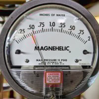
With the stat calling for heat, measure voltage from either of the "T" "T" terminals and the 24V terminal block. Whichever of the two "24V" terminals that gives you and actual 24v reading between that and "T" "T" is the common ("C") side of the transformer. Connect that to "C" on the thermostat.
Bob Boan
You can choose to do what you want, but you cannot choose the consequences.0 -
Just an alternate option. I find that probably 95% of my customer never use “G”. In a pinch, when pulling new wire isn’t practice, I’ve used that for the common, or for Y2 or W2 when nessesary.
I also find most customers could care less about programming their thermostat, so we usually install Honeywell T4 or T6’s and “dumb them down” by disabling the scheduling feature. It can always be turned back on. Also nice that you can swap out to a T6 WiFi, T9 or T10 if you need more functionality. NEST is nice and all if you have a whole NEST network. But I like simple and Honeywell uses CPH for control and you can manually adjust it.1 -
> @Ironman said:
> @MrWizard3
> Your making it more complicated than it needs to be.
>
> With the stat calling for heat, measure voltage from either of the "T" "T" terminals and the 24V terminal block. Whichever of the two "24V" terminals that gives you and actual 24v reading between that and "T" "T" is the common ("C") side of the transformer. Connect that to "C" on the thermostat.(Image)
Not following ya on this. You're saying one TT terminal from a relay can be used to connect to C of a thermostat ?
Wouldn't you need a common maker to do that ?0 -
No, look at the “24v” terminals that I circled in orange. To find which is the “C”, measure voltage between each one and either of the “T” “T” with the stat calling for heat.
The one which shows 24v on the volt meter (of the 24v terminals) is the “Common” terminal.Bob Boan
You can choose to do what you want, but you cannot choose the consequences.1 -
Ahh. I understand now. Thanks. Curious, what's those yellow wires connected to 24 volt power and common ?0
-
They're from the transformer.Bob Boan
You can choose to do what you want, but you cannot choose the consequences.0


Categories
- All Categories
- 87.7K THE MAIN WALL
- 3.3K A-C, Heat Pumps & Refrigeration
- 59 Biomass
- 430 Carbon Monoxide Awareness
- 129 Chimneys & Flues
- 2.2K Domestic Hot Water
- 5.9K Gas Heating
- 122 Geothermal
- 170 Indoor-Air Quality
- 3.8K Oil Heating
- 79 Pipe Deterioration
- 1.1K Plumbing
- 6.6K Radiant Heating
- 396 Solar
- 16K Strictly Steam
- 3.5K Thermostats and Controls
- 56 Water Quality
- 51 Industry Classes
- 51 Job Opportunities
- 17 Recall Announcements