PONPC Question

My understanding is that it Will change. This system apparently blows the relief valve occasionally and I believe the PONPC location is the reason for that.
.
Comments
-
No, when the PONPC is in the primary loop like that, the secondary loop "sees" the primary loop as the PONPC.Bob Boan
You can choose to do what you want, but you cannot choose the consequences.0 -
What model boiler and circs.
Those kind of pressure deltas are not normal in a residential system, Are they measured or theoretical."If you can't explain it simply, you don't understand it well enough"
Albert Einstein 1
1 -
How could 10" of common pipe cause a 20 psi reduction in pressure? Assuming normal size.Zman said:What model boiler and circs.
Those kind of pressure deltas are not normal in a residential system, Are they measured or theoretical.
Bob Boan
You can choose to do what you want, but you cannot choose the consequences.0 -
And what residential circ generates 56 ft of head...."If you can't explain it simply, you don't understand it well enough"
Albert Einstein0 -
Because both Tess are closely spaced, the secondary "sees" the same pressure through both of them.
Technically speaking, the tank should be on the upstream side, but IDK how you came up with those numbers.Bob Boan
You can choose to do what you want, but you cannot choose the consequences.0 -
Hey there Zman.Zman said:What model boiler and circs.
Those kind of pressure deltas are not normal in a residential system, Are they measured or theoretical.
this is a commercial warehouse. 2 ultra 399 boilers where it says B1. Feeds radiant floor loops. The piping is not exact but the connection layout is. They are measured readings. The equipment is on a mezzanine and the floor is 20 feet below. I lowered the tank pressure to 5psi (from 12), which gave me 3 psi over the highest piping above the tank connection point. I did this to lower the pressure, the relief valve was seeing to 22. ( from 25-26) I did this before leaving Friday night so it wouldn't blow again.
0 -
The secondary loop circ.... Taco 1919 7.9
the boiler circs I can't member, I think factory circ is a 0014 but not sure.
0 -
Well I thought the extank ( at 5psi charge) being piped in there was responsible for that?Ironman said:
How could 10" of common pipe cause a 20 psi reduction in pressure? Assuming normal size.Zman said:What model boiler and circs.
Those kind of pressure deltas are not normal in a residential system, Are they measured or theoretical.0 -
The system pressure at the expansion tank is not the pressure the tank is charged. By the looks of it, your system pressure is 25 psi. This is causing your ex tanked charged to 5psi to become ineffective as there is very little room left for expansion.
I would recharge the ex tank to 12psi and then run the system at the same pressure. This will keep your max pressure in the system well below the 30psi relief valve"If you can't explain it simply, you don't understand it well enough"
Albert Einstein

 4
4 -
With tank empty of water, and bladder charged to 5psi, and all pumps off, the pressure at both pumps is 5 psi. With system running, the pressure stays at 5 psi at the connection point and at the tank schreader valve. At the secondary pump inlet it's 5 psi when that pump is running.Zman said:The system pressure at the expansion tank is not the pressure the tank is charged. By the looks of it, your system pressure is 25 psi. This is causing your ex tanked charged to 5psi to become ineffective as there is very little room left for expansion.
I would recharge the ex tank to 12psi and then run the system at the same pressure. This will keep your max pressure in the system well below the 30psi relief valve
I'm not seeing something here. If it's 5 at this point, why wouldn't it be 5 at the primary circuit if the connection point is before the CSTs of the primary?
0 -
The 1919 is a very high head model. I wonder if it is appropriate.
That does explain the 5-29psi numbers.
You should not be at 25psi at the boiler connection, you should slightly higher than 5 psi at that point."If you can't explain it simply, you don't understand it well enough"
Albert Einstein0 -
The tank is "dry" when the system runs. I rocked it and there's nothing but bladder and steel. I don't have the size of it but it's about 4' x 2'.
So thinking about that. IF I open the drain valve on the tank, and allow flow out of it. should it flow hard or just a bit? I was surprised at the low flow when I left the drain open once and it drained thru the 20 foot garden hose in to the barrel.0 -
if the pump was way oversized, would this high return pressure be a symptom?0
-
If the connection point is in the primary loop does that lower what the primary pump sees? I've been reading the various Caleffi idronics manuals and thought I was understanding this but maybe not.
I am appreciating all of the input.0 -
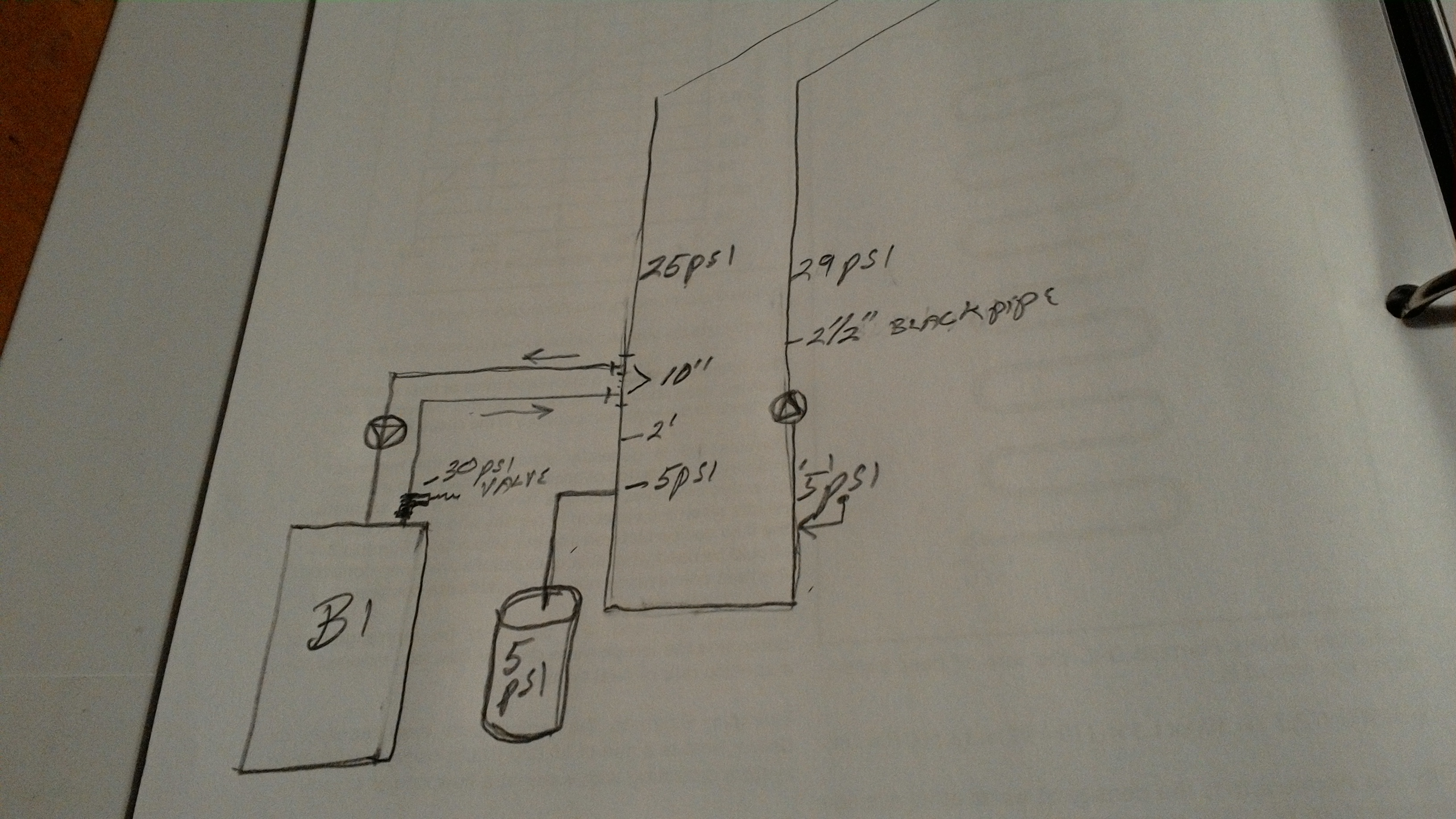
The boiler circ sees the system as it's PONPC. On your system drawing you show 25psi then 3' later you show 5 psi. The system cannot be dropping 20 psi in 3'"If you can't explain it simply, you don't understand it well enough"
Albert Einstein1 -
He’s seeing the differential pressure of the 1919 that circ is yuge.....
I know the emitters are radiant floor. Do they really need that big of a mining pump......
Not that your pressure differential readings of the actual pump would be accurate, but you are looking at 54’ of head running 65 gpm....
0 -
So the questions are .........
Was this always a problem, or a new development?
Are these boilers a fresh install?
Was the 1919 7.9 original to the system?
If so what was the relief valve size of the old boilers?0 -
Your 2.5 inch pipe was like designed for 60 gpm or less. You boiler sizing indicates that the design load is probably in the 600k range.
If you allow 5 feet of head for the emmiters and 5 feet for valves and misc, 2.5" pipe only has a resistance of 2.55/100'. Unless you have 2,000' of distribution piping, this thing doesn't add up. Even if this is huge radiant system, your numbers dont make sense.
The NPSH for that circ indicates that you should have more than 5 psi system pressure to prevent cavitation."If you can't explain it simply, you don't understand it well enough"
Albert Einstein0 -
^I agree on the system pressure. Which doesn’t change the psi differential of the pump.
I’d be installing a pressure gauge setup at the pump to determine the exact pump differential. Which will give you gpm out to the system. Then determine if that gpm delivery is actually needed to the radiant.
One thing is for sure system side flow is greater than boiler side 0
0 -
> @Gordy said:
> So the questions are .........
>
> Was this always a problem, or a new development?
>
> Are these boilers a fresh install?
>
> Was the 1919 7.9 original to the system?
>
> If so what was the relief valve size of the old boilers?
So i havent told the whole story becsuse i just wanted an answer to my original PONPC question.
. Ill have to draw a new pic. But imagine there are 2, yes 2, 1919 7.9 pumps . Each circing 60 to 70 gpm out to their respective loops and returning on a common return. The common return is where my readings were taken.
When i first climbed up to the mezz, my initial thought was WAY over sized pumps.
The boilers fireside were cleaned recently. When the tech did that he said the relief blew. He throttled the secondary pumps suction because thats all he could think of what to do.
So the system is 5 years old i think.
Installed by the co i work for.
A lot of equipment we install does not get sized properly. Particularly pumping. First time ive seen this system, i didnt even know we installed this. Thought wed just done the 40 RTUs. Anyhow.
The pumping is original.
The relief valve is original.
Nothing was measured at startup im sure. A couple guages may have been eyeballed but the tank connection point showed 12 psi with a 11 psi bladder. The relief didnt trip out of sheer luck and low water temps. 130 max.
So at the connection point when i arrived it was 12psi. After my change its 5. So that is consistant. I took readings everywhere i could with my Dwyer digital guage thru petes ports.
All readings were taken with my guage.0 -
Double the pump pleasure.........1
-
So this setup has been in service for 5 years. With out trouble of relief valve discharge, that you know of? Then after cleaning the fireside we have an issue? Which brings us back to what changed?
Any traces that the relief valves were periodically discharging over time?0 -
I apologize for not getting to the point of your original question, but relocating the x tank to lower the psi the relief valve sees is kind of a band aid solution to me.
Usually problems develop with the x tank location from high head pumps. Either not pumping away, and the high pressure differential sucks air into the system, and in some cases causes the fill valve to keep adding water to the system because it sees the lower suction side pressure of the pump as the system pressure.
Or the discharge side of the pump is approaching the relief valves rating. Causing weeping, or complete opening.
So is the fill valve always open to the system? Or is it off once filled to correct system pressure? Is it’s connection point in the area of low pressure? What is it set to?
 1
1 -
> @Gordy said:
> I apologize for not getting to the point of your original question, but relocating the x tank to lower the psi the relief valve sees is kind of a band aid solution to me.
Yes i agree its a bandaid.
>
> Usually problems develop with the x tank location from high head pumps. Either not pumping away, and the high pressure differential sucks air into the system, and in some cases causes the fill valve to keep adding water to the system because it sees the lower suction side pressure of the pump as the system pressure.
>
> Or the discharge side of the pump is approaching the relief valves rating. Causing weeping, or complete opening.
>
> So is the fill valve always open to the system? Or is it off once filled to correct system pressure? Is it’s connection point in the area of low pressure? What is it set to?
The fill is probably always open.Its on the
secondary pump suction side of the CSTs of the boiler loop.
The fill valve I set at 5psi. Its built with a short piping section which can be isolated and bled off, so as to be able to set the valve quickly. I used my guage on that also.
Just returned from taking my kids fishing,(we got skunked!)
Im really thinking the pumps are too big. Per the boiler ROT, it should be say 80 gpm total. But undoubtably the boilers are oversized, and design flow is too high.
I guess its possible that facilities maint adjusted the triple duty valves when they had a no heat. However the valves are thtottled well below the indicator setting on the triple duty valve now, and still the high system pressure. I think its a poor design and i may need to bandaid it to keep the company from looking too bad.0 -
Been thinking about this. If system pressure is 5 psi now, and x tank is charged to 5 psi. How are you raising water 20’ to the high point in the system? That should take 12psi.0
-
> @Gordy said:
> Been thinking about this. If system pressure is 5 psi now, and x tank is charged to 5 psi. How are you raising water 20’ to the high point in the system? That should take 12psi.
Equipment is 20 ft above the infloor. The highest point above thd tank connection point is about 7ft.0 -
Got it, sorry missed that.0
-
Here's a better drawing. Both supply pumps serve separate loops with common return.
I sure appreciate you sticking with me@Gordy
0 -
The 25 PSI on the common return with 5 PSI 7' later, just doesn't make sense. Are you confident in the readings?"If you can't explain it simply, you don't understand it well enough"
Albert Einstein1 -
The only way would be if the piping between the CST, and x tank did not exist........0
-
> @Zman said:
> The 25 PSI on the common return with 5 PSI 7' later, just doesn't make sense. Are you confident in the readings?
I'm really starting to doubt my reading there, or wonder what happened ? I took numerous readings to convince myself that that is what I actually saw. I spent a number of hours at the shop this morning digging out prints, and nothing matches the prints either so I don't know what happened at installation.
I will make sure I get back up there and I will recheck all my data. It may be a few days, but I will be sure to post it here and once again thank you for your help everybody..
Oh! the original print called for one pump at 70 GPM serving both areas. The actual installation is the two pumps serving one area each, so that piping and flow and velocity are all questionable.0 -
I do that all the time in the field only to get back to the office and say ****.
When you are back on site, it would be helpful to know what size and length tubing is in that radiant assembly. Those are some big circs. The risk of cavitation is high with them, especially installed so high in the system. Throttling the intake is always a bad idea."If you can't explain it simply, you don't understand it well enough"
Albert Einstein0 -
. I talked to the installer, he said he's pretty sure that it's 20 300ft half inch Loops. So one pump then would have about 6000 feet on it. (Total pex) He thought the other pump had fewer loops but it also did snowmelt.
Ive no idea on the required gpm. I can find room size tho later.
In a drivethru lumber yard apparently. So a garage door will open and close at times.
Print shows unit heaters too.0 -
So heres the situation.
(In a stage setting)
The audience comprised of @Gordy and @Zman and a couple other vaguely interested individuals are seated waiting for the OP to enter.
Da da! OP enters. Oh my! Hes wearing a a a, oh can it be? A DUNCE CAP!
He holds a picture up and gives an embarrassed chuckle, offers an apology to all for wasting their time. And leaves.
Then he returns to thank them for helping anyhow and mentions that next time he bumps his head on a STRAINER! he'll include it in his thought process.🙂

 4
4
Categories
- All Categories
- 87.6K THE MAIN WALL
- 3.3K A-C, Heat Pumps & Refrigeration
- 59 Biomass
- 430 Carbon Monoxide Awareness
- 124 Chimneys & Flues
- 2.2K Domestic Hot Water
- 5.9K Gas Heating
- 120 Geothermal
- 168 Indoor-Air Quality
- 3.8K Oil Heating
- 78 Pipe Deterioration
- 1K Plumbing
- 6.6K Radiant Heating
- 394 Solar
- 16K Strictly Steam
- 3.5K Thermostats and Controls
- 56 Water Quality
- 51 Industry Classes
- 51 Job Opportunities
- 18 Recall Announcements