ECM CIRC For Small System: Head Calc Changes At Varied Flows

As I’ve come to understand it, one would want a circulator—whether a zone circulator or a system circulator with zone valves––that is sized so that the expected ‘variable’ service points on the pump curve are well within the circulator’s range. Otherwise it will not in fact serve as a variable speed circulator. It seems to me that using zoning valves means losing some ability to tailor both head and flow to each zone in exchange for energy savings.
I have a three-zone 1800 sq ft house, measured heat loss of 38K, let’s say 40K. Actual heat loss—based on annual heat therms, degree days and 75% old boiler efficiency shows less than 30Kbtu loss. Plan is to use one ECM circ with zone valves.
By estimated method, 3/4" copper pipe measured length of the longest pipe run Zone 2 is 200ft x 1.5 = 300ft x .04 = 12 ft head. I believe this estimate method measures head at 4gpm—which may seem logical as cumulative flow requirements for the 38K loss would be 4gpm @10Kbtu. (In this case the estimated head loss TDL nearly equaled the measured TDL of 308ft.)
By calculated head loss method: TDL 308ft x .015psi/ft for 4gpm Type M copper, design day x 2.31 = 10.67ft head or 12.8 ft head for type L. (See table below.) Pretty close to the estimated method, but again both results are based on 4gpm flow.
So I wanted to check the pump curve to verify that the variable speed TACO Taco-VT2218-HY2-4C1A00 ∆T ECM could handle the lowest flow rate or head loss required when any one or two zones is calling for heat on either a design or shoulder day. The calculated head loss method for that Zone 2—based on the 1gpm it actually requires even on a design day--is much lower: 308ft TDL x .001psi/ft x 2.31 = .711 ft of head Type L or M copper 3/4” copper pipe. So would this circulator handle this zone only on a design or any other day the 0-4gpm at the required water temperature and minimum 2ft-per-second velocity? Or even a three-zone heat call on a non-design day. (see pump curve below.)
(Note that on design day (10ºF), of the three zones, two require only 1gpm and one 2gpm. At 40º OT, total heat loss drops from 38k to 20K, about half, meaning a requirement of only 2gpm flow total for all three zones––0.5gpm for the two smaller zones, 1gpm for larger zone. On the pump curve, 0.5gpm shows about 3.5ft of head pressure, though I know with zone valves gpm is measured cumulatively. So that’s where I’m stuck. If I went strictly circulators instead of zone valves, I’d have to find two ECM circs that each produced about 10K btu on design day at 1gpm and one circ that produced 20K, all zones having 1ft of head based on calculated method.)


Comments
-
If you are considering zone circulators and you want that low flow range, some of the ECM style DHW recirculation circulators go pretty low. I have used the B&G Ecocirc e series on single loop applications. You will get the energy savings with any ECM compared to the PSC.
If you want flow balanced to an exact number, find the closest cir to the requirement and add a balancing valve.
If you go with zone valves, I prefer a delta P circulator.
Idronics 16 explains how to develop the system curve, which you overlay on the pump curve to find the OP.
If you can see all the tube, valves and fittings you should be able to nail down pretty circuit pressure dropaccurate numbers without needing to add fudge factors.
https://www.caleffi.com/sites/default/files/coll_attach_file/idronics_16_na_0.pdf
We have a webinar this Thursday on this topic also.
https://www.caleffi.com/usa/en-us/coffee-caleffitm-scheduleBob "hot rod" Rohr
trainer for Caleffi NA
Living the hydronic dream-1 -
Hi David,
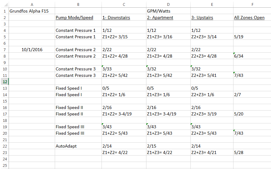
I've had a Grundfos Alpha running on Constant Pressure mode (lowest setting) for almost two years now on my HTP UFT-80W mod-con.
Our setups seems very similar... my house is about 1800 sq/Ft like yours... I also have three zones like you... and my heatloss is about the same as yours on the low 30k BTU range.
Before I went to the mod-con the same radiators were served by two Taco 007's, now I use the single Alpha with three zone valves.... with excellent results.
From my observation I don't think you'll have a problem finding a working setting on a ECM ∆P pump like the Alpha, even if you over flow a bit it won't damage your system. It might take a while to "dial in" the best setting since you will need to setup and observe supply and return temp sensors on your zones over time. You also have to listen to the boiler at high output with just one (your lowest flow) zone running to make sure you're not under-flowing the HX and frying it.
Nice thing about a mod-con is that you can limit the output all the way down to 50% of max (which would probably be perfect for your house) and you can use ramp delay to build up to full output to help extend burn times and keep from stressing the HX by throwing 80K BTU's at it all at once with 1gpm flow through the HX.
If your zones aren't balanced- you always have the option of adding a globe valve to the low head zone(s) to encourage flow through the high head zone(s) too.
One thing to keep in mind is that many people will probably mention to you that the GPM readings on the Alpha are inaccurate. To that end they are correct... I installed low PSI pressure gauges on both sides of my Alpha and calculated the flow rate based on pipe diameter and pressure differential upstream and downstream of the pump. I did find inaccuracies in the Alpha's GPM display... but it's still very useful as is when comparing flow rates with the seven different pump settings as is the "watts" display. When you see "1GPM" with one zone valve open and "5GPM" with three zone valves open- you at least know the pump is working properly and can now try different pump settings an note the flow rates relative to previous settings.
Last thought- Conventional wisdom in the past was ∆P pumps were better suited for mod-cons vs. ∆T pumps that would be "fighting for control" over the boiler's built in temp sensors. Some manufacturers like HTP have updated their control board logic and response time to work with ∆T pumps... but I'd suggest you contact them directly before installing a ∆T pump vs. ∆P pump.-1 -
One last thing....
Be really careful at 1GPM flow rates (you could see that on the lowest fixed speed settings on the Alpha with your setup with just one zone open) ... if you don't limit boiler output or enable step modulation you're throwing 80K instant BTU's at the HX with only 1GPM flow. Quick way to fry the HX... It's critical that you listen to the HX with the cover off the boiler at very high fire rate and low flow rates till you verify you're getting enough flow through the boiler.0 -
Thanks for the comments; will have to read them and the links closely later in depth. Note that the proposed boiler is the smallest Versa Hydro (buffer, boiler and hwh in one.)0
-
Also, if you run a heat source on ODR, varying the SWT, and fixed ∆T circulation, it looks like this:
As SWT drops and flow changes to try and maintain the set 20∆, the output of the emitter drops, sometimes considerable, in this example 55%.Bob "hot rod" Rohr
trainer for Caleffi NA
Living the hydronic dream-1 -
Gentlemen , keep in mind he has stated he is using a Versa Hydro . Very different animal than a low / medium mass boiler .You didn't get what you didn't pay for and it will never be what you thought it would .
Langans Plumbing & Heating LLC
732-751-1560
Serving most of New Jersey, Eastern Pa .
Consultation, Design & Installation anywhere
Rich McGrath 732-581-38330 -
@NY_Rob, @hot rod , @Rich Regret I forgot to post the Taco 2218 ECM pump curve and the head calc table. See below. I do know that with the Versa Hydro the buffer aspect makes the modulation ratio less critical; I can't say what effect that has on circulator choice or whether to go zone circulators or circ with zone valves.
Firstly, can I assume that based on the information I've given and the pump curve that the Taco 2218 is not applicable here? And that the calc table shows that the head for the longest zone ––308ft 3/4" copper––@ the required 1gpm would be less than 1ft head? (Though I can't see every fitting, I do know the house pretty well and know where all the pipe turns --90Els-- have to be and the Tees, Flow Control Valves, etc are visible in the boiler room.)
Note that two of the three zones--including the longest run upon which I based the head calc––are cast iron rads piped in series. Basement is baseboard––I've been told that the buffer of the Hydro could handle that.
Estimated design day AWT would be 130º, 20º ∆T.
Currently old atmospheric gas WM boiler has a Grundfos super brute UPS 15-58 on speed 1. Probably overpumped; some expansion banging in the morning startup.
I will study the links Hot Rod sent me.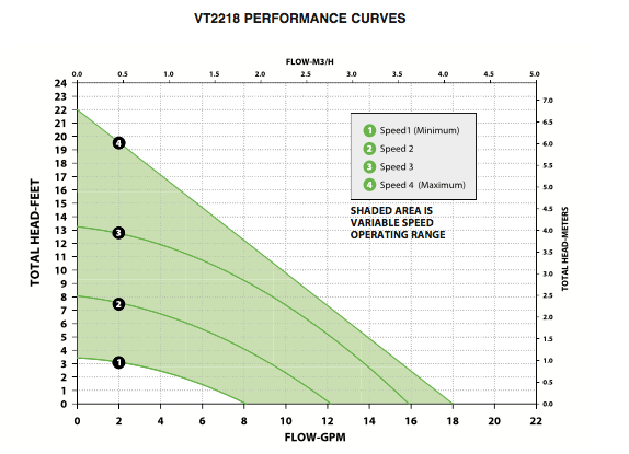

 0
0 -
If the building load is 40K at design and you are designing around a 20∆, you need to move 4 gpm. On the first post you mentioned a 30, 38, and 40K load, and also that you suspect less than 30K. Which number are you wanting to design to?
What is the individual heat load for the 3 zones, and the amount of fin tube in those zones?
The flow rate you need is determined by how much heat energy you need in the zones. The fin tube would be sized to cover that load.
You can work the numbers backward by measuring the heat emitters, determine their output at the temperature you intend to run. How does that match the heat emitter sizing?
Typically fin tube systems are designed around a 180 SWT, if you have adequate fin tube it may be possible to cover the load, even on design days, with lower SWT and increase boiler efficiency.
If you plan on a tank style heat source, should be little to no pressure drop. Does that unit have a minimum flow rate required, being a tank, possibly not?
The baseboard simulator in the HDS software is great for this type of work, as it calculates the temperature drop around the circuit to assure you get adequate output at the end of the loops.
It lets you toggle in various circulators and see the result. It does not have the new ECM circulator selection but does give you required gpm and ft head. Match that to the pump curve with a system curve overlay to see where to circulator will actually operate.
The sizing can be done longhand by following Idronics 16. But you need an accurate load number first.Bob "hot rod" Rohr
trainer for Caleffi NA
Living the hydronic dream-1 -
Any particular reason for going with the $$$$$ Versa Hydro?
You could purchase three HTP UFT-80W boilers and three SS-Ultra indirect tanks for the price of one Versa Hydro.
Major plus going with the UFT vs. the Versa Hydro is that the UFT is a very simple boiler compared with the complex Versa Hydro combo "appliance".
The UFT-80W can also modulate down to 8K BTU's vs. a minimum output of 30K BTU's for the smallest Versa Hydro.
The UFT-80W can output 180F water for spaceheating vs. 160F max spaceheating water from the Versa Hydro.
Since your current radiation was designed/sized based on 180F supply water, you may find that on a near/below 99.9% design temp day that 160F supply water may not hot enough to keep up with heatloss.-1 -
see my answers in italics below:hot rod said:
If the building load is 40K at design and you are designing around a 20∆, you need to move 4 gpm.
Yes, the capacity to move 4gpm if all three zones are calling at once and if there's one circ pushing 3 zone valves as I understand it. But if one zone only is calling then that would require only 1gpm at, according to the measured head of 1ft. Two of the three zones are around 10K loss each and thus require 1gpm; third zone is around 20K loss and thus requires 2gpm. So whether it's zone circulators or circ and ZVs it would have to handle those scenarios.
On the first post you mentioned a 30, 38, and 40K load, and also that you suspect less than 30K. Which number are you wanting to design to?
Guess we'll have to go with the 38K since that's the official heat loss but we'll keep in mind that it's likely less.
What is the individual heat load for the 3 zones, and the amount of fin tube in those zones?
Zone 1, loss is 17.8K, gain of cast iron rads is 16K; Zone 2 loss is 10K, cast iron rad gain is 11.5K; basement zone loss is 11.1k, fin tube gain is 6.7k way under-radiated. These gain figures are at the AWT design day of 130º. I have attached a pdf of all the measured losses and emitter gains per zone and room.
The flow rate you need is determined by how much heat energy you need in the zones. The fin tube would be sized to cover that load.
You can work the numbers backward by measuring the heat emitters, determine their output at the temperature you intend to run. How does that match the heat emitter sizing?
Typically fin tube systems are designed around a 180 SWT, if you have adequate fin tube it may be possible to cover the load, even on design days, with lower SWT and increase boiler efficiency.
If you plan on a tank style heat source, should be little to no pressure drop. Does that unit have a minimum flow rate required, being a tank, possibly not?
The baseboard simulator in the HDS software is great for this type of work, as it calculates the temperature drop around the circuit to assure you get adequate output at the end of the loops.
It lets you toggle in various circulators and see the result. It does not have the new ECM circulator selection but does give you required gpm and ft head. Match that to the pump curve with a system curve overlay to see where to circulator will actually operate.
The sizing can be done longhand by following Idronics 16. But you need an accurate load number first.0 -
HI Rob see my answers below in italics
It is hoped that the Hydro buffer aspect would handle this fin tube zone, though I have seriously considered putting in cast iron rads in the basement to even up the zones. Currently our whole house is heated by the oversized old low mass WM boiler at a maximum of 160º but probably hardly ever reaches that SWT due to short cycling. I won't bother with any modcon unless it can handle that fintube--if I don't replace it with cast iron--at the 130 AWT. Hoping the Versa buffer tank factor can handle it.NY_Rob said:Any particular reason for going with the $$$$$ Versa Hydro?
You could purchase three HTP UFT-80W boilers and three SS-Ultra indirect tanks for the price of one Versa Hydro.
I did get a price from a contractor for the UFT-80 plus a small Turbomax--so as to get a buffer in the bargain, and that turned out to be more expensive than the Versa Hydro, probably due to the simplified piping for the Hydro.
Major plus going with the UFT vs. the Versa Hydro is that the UFT is a very simple boiler compared with the complex Versa Hydro combo "appliance". The UFT-80W can also modulate down to 8K BTU's vs. a minimum output of 30K BTU's for the smallest Versa Hydro. The UFT-80W can output 180F water for spaceheating vs. 160F max spaceheating water from the Versa Hydro.
The Versa Hydro brochure says "The modulating burner operates at a 5 to 1 turndown ratio, while the space heating module operates at a 10 to 1 turndown ratio." As I understand it that means the combustion can modulate from 130K down to 26K (5 to 1), and the space heating module can modulate via pumping from the 26K down to 2.6K--10 to 1 which is lower than almost any modcon I've seen.
Since your current radiation was designed/sized based on 180F supply water, you may find that on a near/below 99.9% design temp day that 160F supply water may not hot enough to keep up with heatloss.
0 -
Not real familiar with this unit, but if I read the manual correctly (page 14) it looks like 30,000 BTU is the minimum firing rate.
http://www.htproducts.com/literature/lp-314_0417.pdf
-1 -
^ I also saw the minimum fire rate as 30K BTU's in the install manual. The sales brochure states 10:1 turndown for spaceheating which would indicate 13K BTU's minimum output for spaceheating.
Maybe time to call HTP for some clarity?
Here is a quick/basic google shopping search for the Versa Hydro: https://www.google.com/search?q=htp+versa+hydro+phe+130+55&client=firefox-b-1&source=univ&tbm=shop&tbo=u&sa=X&ved=0ahUKEwiT1e320eLbAhWDmVkKHdF3BI8QsxgImwE&biw=1440&bih=743
Here is a quick/basic google shopping search for the UFT-80W:
https://www.google.com/search?q=htp+UFT-80W&client=firefox-b-1&source=univ&tbm=shop&tbo=u&sa=X&ved=0ahUKEwist9qm0uLbAhXixlkKHQ0ZDoEQsxgIKA&biw=1440&bih=743
Huge cost difference between the two...
To add an indirect is literally the cost of the indirect, two 1" copper pipes, a standard pump and two flanges... no way that would approach the cost of the Versa Hydro. Can't see how the contractor came up higher on the UFT + indirect?
On that short 26' fintube basement zone- to address short-cycling in the near term... you could probably just leave it's zone valve open all the time so it gets flow any time one of the other zones are calling for heat. You're not going to get a lot of heat out of that short length of radiation at 130F so not much chance of oveheating the area. If it gets too warm (which I doubt would happen) with the zone valve open all the time- you could add a globe valve or try jumpering it to one or the other zones and see how the temps workout like that. You need to get a little creative with short zones.
Once you add to or replace the fintube with cast iron radiators activate the zone valve from it's own t-stat as SOP.-1 -
@ScottSecor @NY_Rob Yes I see the 30k min firing rate. Based on the 5-1 turndown from 130K my math said 26kbtu but perhaps it's not an exact 5 to 1. Anyway, the important thing for me was I was definitely told that the 10 to 1 turndown is available from the lowest firing rate. So if it's 30K btu, the lowest space heating module rate would be 3K. This was not said by HTP, but such a low modulation rate made this very attractive--even though due to the built-in buffer, the modulation is not as crucial. If lowest modulation is 13K, then I'm disappointed, since my lowest heat load on a 50º day for Zone 2 would be 3000btu. But perhaps the buffer covers that too.
As far as costs differentials between the Hydro and UFT-80 with indirect, apparently it's due to the fact that much of the piping for the Hydro comes within it compared to that required for a stand-alone mod-con. The Turbo Max seemed like a good way to combine an indirect with a buffer tank, which I'd probably need in my small system--especially given the basement slantfin zone--and avoid having a separate buffer tank which would significantly enlarge the footfprint. Versa Hydro is a great way to save space.
That's a great idea Rob to keep the basement zone valve open all the time. I truly appreciate everyone's helpful comments and links--probably at no other site in the world I could get all this assistance in navigating through the sizing, hydraulics and hard water issues. Sometimes I feel like these modcons are like dandified poodles--I appreciate the science behind the efficiencies but......0 -
The clarity is that the burner / Hx is within 55 gallons (minimum) of DHW , space heating TDR is based on the programming and 008 circ moving water through the FPHX . This circ is also variable speed based on information from supply and return sensors . There are 2 programs within this machine , 600 programming for DHW and 925 programming for heating .
1 VT2218 and 3 Caleffi 132 quick setters will address any potential issues . His contractor/s are probably able to purchase HTP products for far less than what you'll find on any google search , matter of fact , I know they can . 3 Ufts and superstors would actually cost much more than a Versa Hydro .
Op linked to a heat loss above and a radiator survey has been performed by a qualified contractor and his temps will be fine , see the spreadsheet attached above .
I have attached the results of a similar system and how it consumes . This system however is 14 zones of radiant , 4 adult occupants , shower daily , cook at home , wash lots of clothes . Have a look , you'll be shocked . Everything and everyone is not only obsessed with first cost , this should probably be considered when attempting to assist folks . By the way , this home I attached to is 4000 sf , 14 zones , loss at -7* is 41,000 BTUh . Micro zones cannot be done ? NONSENSEYou didn't get what you didn't pay for and it will never be what you thought it would .
Langans Plumbing & Heating LLC
732-751-1560
Serving most of New Jersey, Eastern Pa .
Consultation, Design & Installation anywhere
Rich McGrath 732-581-3833 0
0 -
I remember a project where there was a system reactive ECM circ (don't remember if it was delta T or delta P) on a reheat coil providing heat as needed to a gym. As loads got smaller there was an overheating issue (circ's min curve not low enough). Solved by slightly throttling a discharge valve, fooling the circ into thinking it was seeing more pipe (higher friction loss). We (product management) didn't want to lower the min curve software as this might cause additional issues with minimum flow rates (or flow stalling) when the circ is providing flow through the boiler.
David, I read a couple of comments with opinions of pressure (delta P) vs temperature (delta T). All applications will work with delta T, not all with delta P.
Your application will work with either control (we have both so it's your call). Nice thing about delta P (our VR 1816) is that you don't need to worry about temperature transducer installation and is easier to set up. Delta T (our VT 2218) displays flow, watts AND system supply/return temp. 0
0 -
David, I read a couple of comments with opinions of pressure (delta P) vs temperature (delta T). All applications will work with delta T, not all with delta P.
Steve, you don't see any issues with boiler reset, and constrained ∆T circulator operation?
The analysis, based in the "hydronic formula" and manufacturers certified output data, clearly shows a significant drop in emitter output as the imposed ∆ is applied? Your thoughts?
Kinda indicates BTUs have no problem jumping off a fast moving train, but surely do as the train slows")
Seems a slow responding high mass emitter would further complicate this type of logic? A number of installers here have experienced this inadequate output condition.
Also, heat emitters respond to the temperature of the space where they are located. If you want heat emitters to respond to outdoor temperature, mount the fin tube on the outside of the building
The air temperature entering the fin and the SWT in the tube dictates the output, period.
Bob "hot rod" Rohr
trainer for Caleffi NA
Living the hydronic dream0 -
Bob ,
Would you consider a radiant slab the highest mass , slowest responding emitter we could build ? If so , please refer to the results in actual fuel usage I posted above . That house has 1 bumble bee performing the duties for 3 remote manifolds with 13 zones , oversized supply and return piping ( less piping loss ) . Time is here to evolve Bob .
I would also point out that you are posting lots of screenshots of writings all referring to fin tube baseboard while the system being discussed is in fact a majority of cast iron rads . The largest problems we face and have faced is getting lower output during low load times , yet you and others continue to fail to see how slower moving fluid at these times is just what we need .
I know this is not a mystery to you , or at least I hope it's not . We design systems around a Delta T Bob . Head loss changes , , flow rates change , SWTs & AWTs change , firing rates change , outdoor temps change , run times change . Yet boilers are all rated at a 20* Delta T for AFUE . These are systems Bob and we must do what's best toward that end .
In response to the following
Also, heat emitters respond to the temperature of the space where they are located. If you want heat emitters to respond to outdoor temperature, mount the fin tube on the outside of the building
The air temperature entering the fin and the SWT in the tube dictates the output, period.
You forgot one very important factor here . The air temp directly surrounding the tube wall containing the Fluid rapidly heats up the small area inside the cabinet . When this happens the water inside the tube walls sheds less BTUs as the Delta is narrower than if we kept the water moving at a rate where the water can shed those BTUs to the reservoir ( room) . This is why Deltas narrow Bob , because the SWT , air flow and T air are not in synch and when Deltas narrow the fluid can do little work . It's a shame we had to ever use fans to move that heat outta emitters when a simple logical circ might have done the trick .
Makes me wonder how those gravity systems worked before circs and fans and mechanical stuff .
You didn't get what you didn't pay for and it will never be what you thought it would .
Langans Plumbing & Heating LLC
732-751-1560
Serving most of New Jersey, Eastern Pa .
Consultation, Design & Installation anywhere
Rich McGrath 732-581-38330 -
Rich said:
Bob ,
Would you consider a radiant slab the highest mass , slowest responding emitter we could build ? If so , please refer to the results in actual fuel usage I posted above . That house has 1 bumble bee performing the duties for 3 remote manifolds with 13 zones , oversized supply and return piping ( less piping loss ) . Time is here to evolve Bob .
The data you posted without actual building loads really doesn't tell much of a story. Identical weather, wind, temperature inside settings? looks like it uses more electricity, not less. Not knowing what else is in the gas and electric bills,?? case in point electrical consumption going up? The hot tub? Data loggers are a good way to store and record data for comparisons.
I would also point out that you are posting lots of screenshots of writings all referring to fin tube baseboard while the system being discussed is in fact a majority of cast iron rads . The largest problems we face and have faced is getting lower output during low load times , yet you and others continue to fail to see how slower moving fluid at these times is just what we need .
Why not simply lower SWT at lower load conditions, most boilers have that feature and some electronic mixing valves can also do that. I profess that lowering SWT and flow rate causes the large output droop. The higher mass system, be they slabs or iron and fluid respond slower and the flow and temperature change with ∆T and temperature reduction do match well with high mass. assuming comfort is also part of the equation? Over or undershooting the t-stat setting is not a goal.
I know this is not a mystery to you , or at least I hope it's not . We design systems around a Delta T Bob . Head loss changes , , flow rates change , SWTs & AWTs change , firing rates change , outdoor temps change , run times change . Yet boilers are all rated at a 20* Delta T for AFUE . These are systems Bob and we must do what's best toward that end .
Of course we design to a "chosen" ∆, but the system output will change as you go above or below that design. Knowing the load is dynamic, why not let ∆ vary to match loads? A rapid drop in room temperature, the ∆ adjusts quickly to match the load. If you constrain the ∆, you just pulse input and it may not be enough. Not sure why 20∆ was chosen for AFUE, I suspect an 18 or 22∆ would not change AFUE much?
In response to the following
Also, heat emitters respond to the temperature of the space where they are located. If you want heat emitters to respond to outdoor temperature, mount the fin tube on the outside of the building
The air temperature entering the fin and the SWT in the tube dictates the output, period.
You forgot one very important factor here . The air temp directly surrounding the tube wall containing the Fluid rapidly heats up the small area inside the cabinet . When this happens the water inside the tube walls sheds less BTUs as the Delta is narrower than if we kept the water moving at a rate where the water can shed those BTUs to the reservoir ( room) . This is why Deltas narrow Bob , because the SWT , air flow and T air are not in synch and when Deltas narrow the fluid can do little work . It's a shame we had to ever use fans to move that heat outta emitters when a simple logical circ might have done the trick .
Fin tube is a convector, that air movement across the moves the energy. If you cover the fins, or close the damper temperature inside the cabinet could rise. the convection current changes as the ∆ changes. That is why high temperature fin tube tends to strip the wall with dust, faster air movement.
Fans are added to fins to increase output, more energy transfer in a smaller package, air coils, kickspace heaters, etc.
Makes me wonder how those gravity systems worked before circs and fans and mechanical stuff .
Hot water, like hot air rises, large pipes, low pressure drop, some pitch allowed them to work. Balancing required.
Steve mentioned all systems work with ∆T but not with ∆P. Makes one wonder why you would need to develop ∆P circulators at all? I recall someone suggesting ∆P was for European systems, not for US systems.Bob "hot rod" Rohr
trainer for Caleffi NA
Living the hydronic dream0 -
Bob asked , "Steve mentioned all systems work with ∆T but not with ∆P. Makes one wonder why you would need to develop ∆P circulators at all? I recall someone suggesting ∆P was for European systems, not for US systems."
Probably would have something to do with a partnership with a European manufacturer ( Askoll ) and , well , market share and sales opportunities here also .
Bob also , " The data you posted without actual building loads really doesn't tell much of a story. Identical weather, wind, temperature inside settings? looks like it uses more electricity, not less. Not knowing what else is in the gas and electric bills,?? case in point electrical consumption going up? The hot tub? Data loggers are a good way to store and record data for comparisons."
More electricity in the summer Bob , that is clear by what I posted . That Hot tub that was put in this past year certainly won't help electric consumption . By what is posted also , one can clearly see that NG consumption during the heating season does not go up that much and January / February are the coldest months . I attached the data again and the panel reports at 40* and 7* .
I certainly do not believe I am the only individual that can employ ODR and Delta T pumping in any type of system successfully , I am not that special Bob .You didn't get what you didn't pay for and it will never be what you thought it would .
Langans Plumbing & Heating LLC
732-751-1560
Serving most of New Jersey, Eastern Pa .
Consultation, Design & Installation anywhere
Rich McGrath 732-581-38330 -
Here is what I would like to see, and several posters over the years have done this type of number crunching.
With a standard fixed speed circulator run a system for a period of time, weeks months maybe a season ideally. Track the fuel consumption, and grab the degree days from a local weather station database. Then normalize that data and come up with some real numbers logged from actual use.
Replace the cir with a constrained ∆ function circ, change nothing else, same stat settings, same boiler operating logic and condition, etc. Track and normalize the data and compare. Obviously occupant use could vary some, it's not a true lab environment study, although that could certainly be done.
I suspect the fuel savings would be little if any by changing to a ∆T circulator only.
I've re-read many of your past posts and I think I keep hearing you say slowing the flow increases heat output? Am I wrong?
Would you agree it is going to take X amount of fuel to heat a space, home, building for a period of time? Fuel required-degree days.
The mechanism to move that energy cannot change that amount.
True some electrical consumption may go down with ECM technology, I doubt the fuel use changes much, all things being equal.
You will always be special in my eyes, don't sell yourself short Bob "hot rod" Rohr
trainer for Caleffi NA
Living the hydronic dream0 -
@hot rod Great discussion. A few questions:
1. So you're saying regardless of ECM mode, ∆T, ∆P, ∆P Proportional, etc. only real savings would be electrical?
2. That unlike modulating condensing boilers that capture stack losses, ODR that saves by not overheating the supply water, buffer tanks that prevent losses from short-cycling, that the fine-tuning done in real time by the ECM will not prevent excess generated heat usually lost with the standard circulators?0 -
David107 said:
@hot rod Great discussion. A few questions:
1. So you're saying regardless of ECM mode, ∆T, ∆P, ∆P Proportional, etc. only real savings would be electrical?
2. That unlike modulating condensing boilers that capture stack losses, ODR that saves by not overheating the supply water, buffer tanks that prevent losses from short-cycling, that the fine-tuning done in real time by the ECM will not prevent excess generated heat usually lost with the standard circulators?
I have seen data that proves electrical consumption is less, with ECM motor technology. It's not hard to understand that with a more efficient motor.
Sure distribution efficiency can be increased, electrical pump consumption reduced by tracking the circulators performance and matching it as closely as possible to the load. Velocity noise, pipe and fitting wear can be minimized by adjusting and reducing flow rates.
I have yet to see any non biased, third party verification that a more efficient pump motor alone reduces fuel consumption?
Upgrading the building envelop, upgrading the boiler type and efficiency, properly sizing the boiler, tuning the boiler with a combustion analyzer, are proven ways to reduce fuel consumption.
If a boiler is short cycling, wasting fuel due to oversizing or inadequate flow I'd chose to address that with a modulating boiler, properly sized boiler, or maybe a buffer tank, or high volume heat source. That could reduce fuel consumption. A smart pump doesn't correct mis-sized heat sources.
If you have a fixed speed 90K boiler connected to a 30K load, constraining the ∆T will just allow the boiler to hit operating setpoint quicker, the circulator may run longer cycles, basically a flow limiter device, and may or may not be able to keep up with the load if ODR is used also, again refer to the graph shown above.
Show me verified hard data, not marketing spin confirming fuel savings by just changing circulator operating logic, nothing else in a system?
My opinion is it doesn't exist because it isn't possible.
I've laid out my numbers.Bob "hot rod" Rohr
trainer for Caleffi NA
Living the hydronic dream-1 -
If you're going to go with a fixed speed pump then you need to account for the difference in flow when one zone valve is open vs three zones open. You may need to install a differential pressure bypass valve to ensure minimum flow thru the HX. If you go with a ∆P pump it's not needed as the pump will ramp up or down to maintain a minimum flow based on the pump settings even if just one zone is open.
This setup uses a differential pressure bypass valve and a fixed speed circulator...
-1 -
@NY_Rob Thanks, not really leaning towards fixed-speed circ but good to have your input. I will of course have to consider how well my existing piping can be cleaned of ferrous materials or debris in preparation for an ECM with that magnet inside.
From an industry source very experienced with ECMs:
"I’m going to lean towards the fact that the pump itself is not responsible for the boiler heat output/btu usage. It is only the delivery man. I’m familiar with the long standing argument about controlling delta t somehow decreases btu consumption but have never been truly convinced. What I do believe, however, is that when a circulator goes from being fixed speed to being controlled in any mode, there can be masked symptoms that are alleviated by controlling the flow through the system.
For example:
3 - 399 btu Weil McClain boilers piped primary secondary to a distribution loop for multiple buildings. The existing pumps were fixed speed, 100%redundancy, so only one pump ran at a time. These pumps were of course sized for worst case scenario and ran full speed all the time to be able to deliver the load when they were at design point. Design point was 20 below zero. It is only 20 below a small fraction of the time meaning the pumps are too big 95+ percent of the time.
The symptom was quite obvious when in the mechanical room. The boilers would fire off and on non stop (short cycling) whenever the demand from the buildings was not at capacity. 95+ percent of the time. We replaced only the pumps. No piping was changed or any equipment added.
The pumps were installed with VFD’s and controlled on delta t. (That control mode was chosen because of the system design, not because there is or should be a “superior” control mode of one is better than the other). Any argument that claims one control mode is superior is most likely related to an attempt at marketing. The fact is control modes should be chosen for the individual type of system and not because the pump is red or green.
The pumps were now controlled and delivering the correct amount of btus to the system. This resulted in the boilers not short cycling. The end users gas bill was reduced dramatically and the pumps were monitored once a week for a year and their power consumption went down 67%.
So, long story long, a controlled pump is superior to a non controlled pump, and can help to alleviate hidden or obvious system issues to make the whole thing work better.
I used to work a gentlemen who always told me “You’re only as efficient as your system”. Meaning high efficiency equipment in and of itself does not translate to an efficient system."
1 -
Don't sweat that part, give it a good long flush out and install the 3-in1 Dirtmag... multiple problems solved...David107 said:I will of course have to consider how well my existing piping can be cleaned of ferrous materials or debris in preparation for an ECM with that magnet inside.
https://www.supplyhouse.com/Caleffi-546196A-1-Sweat-5461-Series-DISCAL-DIRTMAG-Air-Dirt-Separator-with-Magnet
-1 -
If it helps, here's my actual observations from my system with the Alpha pump. The measurements are GPM/Watts from the Alpha's display- 1/12 means 1GPM at 12Watts, etc....
-1 -
David107 said:
@NY_Rob Thanks, not really leaning towards fixed-speed circ but good to have your input. I will of course have to consider how well my existing piping can be cleaned of ferrous materials or debris in preparation for an ECM with that magnet inside.
From an industry source very experienced with ECMs:
"I’m going to lean towards the fact that the pump itself is not responsible for the boiler heat output/btu usage. It is only the delivery man. I’m familiar with the long standing argument about controlling delta t somehow decreases btu consumption but have never been truly convinced. What I do believe, however, is that when a circulator goes from being fixed speed to being controlled in any mode, there can be masked symptoms that are alleviated by controlling the flow through the system.
For example:
3 - 399 btu Weil McClain boilers piped primary secondary to a distribution loop for multiple buildings. The existing pumps were fixed speed, 100%redundancy, so only one pump ran at a time. These pumps were of course sized for worst case scenario and ran full speed all the time to be able to deliver the load when they were at design point. Design point was 20 below zero. It is only 20 below a small fraction of the time meaning the pumps are too big 95+ percent of the time.
The symptom was quite obvious when in the mechanical room. The boilers would fire off and on non stop (short cycling) whenever the demand from the buildings was not at capacity. 95+ percent of the time. We replaced only the pumps. No piping was changed or any equipment added.
The pumps were installed with VFD’s and controlled on delta t. (That control mode was chosen because of the system design, not because there is or should be a “superior” control mode of one is better than the other). Any argument that claims one control mode is superior is most likely related to an attempt at marketing. The fact is control modes should be chosen for the individual type of system and not because the pump is red or green.
The pumps were now controlled and delivering the correct amount of btus to the system. This resulted in the boilers not short cycling. The end users gas bill was reduced dramatically and the pumps were monitored once a week for a year and their power consumption went down 67%.
So, long story long, a controlled pump is superior to a non controlled pump, and can help to alleviate hidden or obvious system issues to make the whole thing work better. I used to work a gentlemen who always told me “You’re only as efficient as your system”. Meaning high efficiency equipment in and of itself does not translate to an efficient system."
In your application you are talking about a system pump, different application than a primary loop pump.
Boilers and primary loop piping like mentioned above are typically supplied with individual circulators and often, and ideally, varied with the burner modulation, an example below, from Young Services. Delta P circs on the distribution.
There are a number of great applications for ∆T control, often ignored. We showed one yesterday in the presentation as a primary loop temperature control, similar to the example you mentioned. Although primary loop pumps probably should disappear. Really no need to add another circ when we have separators and fire tube boiler design. Unless it is a loop throughout the building of course.
Injection mixing, although not as common these days with mod cons boilers. I worked with the UFC ∆T folks back in 1999, great application for ∆T circulator.
Boiler return protection, properly piped is another application, I've been showing this piping example, how to use ∆T for 3 years or so in my trainings.
Chilled water air coils need a tight ∆ for condensation control, Belimo does it with a clever ∆T valve, a ∆ circulator, if it can handle the temperatures could be applied.
I'd like to see more emphasis on these applications.
For a system pump, especially on a ODR system, I don't see it working as presented.
Use ∆T circulators where they really work and add benefits and control required. I'm not anti ∆T circulator, I have a few in my wood boiler/ solar system in my shop.
It's really about how you apply the technology, and understanding the concepts of heat transfer as related to flow and temperature changes.
Hence Idronics 23Bob "hot rod" Rohr
trainer for Caleffi NA
Living the hydronic dream-1 -
Bob said , " I have yet to see any non biased, third party verification that a more efficient pump motor alone reduces fuel consumption? "
I say , I am a non biased third party folks .
I used pressure circs before any Delta T technology appeared . When Delta T technology appeared it intriqued me , so I tried it . Then tried it again in a different scenario and so on for several applications . I still use P circs at times . I never looked back . Alot of thought goes into every project before deciding on a circ , I analyze what every part of a given system will doYou didn't get what you didn't pay for and it will never be what you thought it would .
Langans Plumbing & Heating LLC
732-751-1560
Serving most of New Jersey, Eastern Pa .
Consultation, Design & Installation anywhere
Rich McGrath 732-581-38330 -
To answer your original question, if you shop the Euro market you find a wider selection of small output circs. Find them online easily enough if you don't mind dealing with 220V
I've heard rumors recently that this small ∆P Wilo may make it to North America.
Pump graphs are metric units, by the way.Bob "hot rod" Rohr
trainer for Caleffi NA
Living the hydronic dream-1 -
My remaining issue is a need for a little more clarity on how the VT2218 circulator is going to handle the 10K zones, which require 1gpm, and the 1ft head. On the attached pump curve, 1gpm gives 3.5ft head; at 1ft head, flow is almost 7gpm. My requirements SEEM to be below the circ's operating range for only one and two zones operating.

0 -
You need a smaller circulator or a balance valve to adjust it to the GPM.
A good balance valve for that is a PIBV pressure independent balance valves You find them often on fan coils so the coil ALWAYS gets the exact flow regardless of how many zones, coils are calling. The coil manufacturers add them at the factory assembly or kits can be added at the installation. It's a large OEM product market.
The attached graphics show the difference in how a manual balance valve works compared to a PIBV.
They work really nicely with ∆P circs, page 48
If you want the background on how and why, page through Idronics 8. It is a fairly math and formula intensive topic
It's best to read the entire journal, not just the section on PIBV so you get a grasp of the finer points of balancing, and why there are so many choices of valves.
https://www.caleffi.com/sites/default/files/coll_attach_file/idronics_8_0.pdfBob "hot rod" Rohr
trainer for Caleffi NA
Living the hydronic dream-1 -
Keep in mind that the boiler's HX adds possibly 1-2ft of head (or more at higher flow rates), so your 1ft head zone is actually 3ft of head.David107 said:My remaining issue is a need for a little more clarity on how the VT2218 circulator is going to handle the 10K zones, which require 1gpm, and the 1ft head.
Take a look at the boiler's install manual, there will be a pressure drop chart in there somewhere.
-1 -
1 GPM at 1' will be a challenge for all of the current ECM circs as it is below all min curve settings. This could be corrected by throttling (increasing the system head by 2').
The VT 2218 will overshoot temperature requiring it to be shot off. Our delta P circ (and all others) will have the same issue (only the small zone calling).-1 -
Here is graphical example of what Steve is explaining.
In this conceptual example, a low pressure drop circuit, we took low IQ (just kidding Steve smart pump and gave it a Caleffi valve tweak. Unless the algorithms have been changed in boiler protection mode? It doesn't slow down less than about 30% in that mod. The cir would not operate in that white wedge shaped zone at the bottom, so not able to provide adequate return protection to the boiler. So adding some additional "adjustable" pressure drop forces the pump up to the curve.
The 3 system curves indicate where the OP moves to as resistance is applied.
While some pump guys abhor PAB valves here is a simple, inexpensive, non electric adjustment that gives you more us-ability and allows the circ to perform the return protection as required. Makes a smart pump even smarter.
In your case, if you numbers are correct, it will be a hard stretch to get to 1 & 1.
Zone valve it, throw in a ∆P cir, add dynamic balancing valves if you want that accuracy and call it good.
Use a pump to move flow, use the boiler temperature modulation to adjust emitter output.
Emitter output, any emitter is proportional to the difference between SWT and room air, almost a perfect slope, very linear, look at ODR reset curves for an example of this.
As I showed you above you get a "hockey stick" shape, non-linear output when you use flow regulation as a temperature adjustment, not so easy to dial in, and sometimes not possible.
Probably why the Germans (Viessmann and others) prefer constant circulation, let 'er flow constantly, adjust the SWT to what the room needs at any given point, simple, effective, and very accurate.Bob "hot rod" Rohr
trainer for Caleffi NA
Living the hydronic dream-1 -
Thanks to all, you've shown me many options. I'll be doing some of the required reading. I'm assuming Rich's quicksetters, Hot Rod's PIBVs, PABs, Steve's 'throttling' are slightly different ways of accomplishing the same thing; or find a smaller ECM, though having some kind of balancing valves with any circ/zvs seems like a good idea. May not be crucial to get the flow perfect--every little addition does add to the cost and complexity of the system. I'll see what options the contractor prefers.
The 'boiler protection' you speak of I assume is preventing shock to the HX from too quick a return water temp change? Since this is a mod-con Versa Hydro, not the kind of protection atmospheric boilers need from condensing return temperatures.0 -
The example was just to show the result of adding resistance, nothing to do with your system.
You have a plan, look for a smaller circulator, or tune in an oversized one, or let it over pump that zoneBob "hot rod" Rohr
trainer for Caleffi NA
Living the hydronic dream0 -
Numbers on paper and graphs by folks who have very obvious conflicts are not the real world . I operate in the real world and could give a rat's **** how stuff works in a lab setting , that is of course until my customers or myself live in a lab . I do understand your position on Delta T Bob , I really do , I'll leave it at that and not delve further into my theories on yours and others' stance on the subject .hot rod said:David107 said:@hot rod Great discussion. A few questions:
1. So you're saying regardless of ECM mode, ∆T, ∆P, ∆P Proportional, etc. only real savings would be electrical?
2. That unlike modulating condensing boilers that capture stack losses, ODR that saves by not overheating the supply water, buffer tanks that prevent losses from short-cycling, that the fine-tuning done in real time by the ECM will not prevent excess generated heat usually lost with the standard circulators?
I have seen data that proves electrical consumption is less, with ECM motor technology. It's not hard to understand that with a more efficient motor.
Sure distribution efficiency can be increased, electrical pump consumption reduced by tracking the circulators performance and matching it as closely as possible to the load. Velocity noise, pipe and fitting wear can be minimized by adjusting and reducing flow rates.
I have yet to see any non biased, third party verification that a more efficient pump motor alone reduces fuel consumption?
Upgrading the building envelop, upgrading the boiler type and efficiency, properly sizing the boiler, tuning the boiler with a combustion analyzer, are proven ways to reduce fuel consumption.
If a boiler is short cycling, wasting fuel due to oversizing or inadequate flow I'd chose to address that with a modulating boiler, properly sized boiler, or maybe a buffer tank, or high volume heat source. That could reduce fuel consumption. A smart pump doesn't correct mis-sized heat sources.
If you have a fixed speed 90K boiler connected to a 30K load, constraining the ∆T will just allow the boiler to hit operating setpoint quicker, the circulator may run longer cycles, basically a flow limiter device, and may or may not be able to keep up with the load if ODR is used also, again refer to the graph shown above.
Show me verified hard data, not marketing spin confirming fuel savings by just changing circulator operating logic, nothing else in a system?
My opinion is it doesn't exist because it isn't possible.
I've laid out my numbers.
For anyone interested , David 107 , Here is a link to several pieces written by John Barba , disclaimer , John does work for Taco . There are key points in all of these pieces but I direct you to Anthony's voice , beginning on page 23 .
http://flopro.taco-hvac.com/images/BestOfBarba_BLOGS_interactive.pdf
Bob keeps calling for verified data , problem is this comes from a lab and is almost always paid for by the interested parties . Recommendations and word of mouth from actual users , contractors are regularly discounted by Bob , as if we are all liars or something , it is quite frustrating .
th
Use whatever device that will allow you to insure a minimum head of 3.5' on each circuit at a flow of 1 gpm . I suggest a simple globe valve .David107 said:My remaining issue is a need for a little more clarity on how the VT2218 circulator is going to handle the 10K zones, which require 1gpm, and the 1ft head. On the attached pump curve, 1gpm gives 3.5ft head; at 1ft head, flow is almost 7gpm. My requirements SEEM to be below the circ's operating range for only one and two zones operating.
You didn't get what you didn't pay for and it will never be what you thought it would .
Langans Plumbing & Heating LLC
732-751-1560
Serving most of New Jersey, Eastern Pa .
Consultation, Design & Installation anywhere
Rich McGrath 732-581-3833-1 -
Rich mentioned:
Numbers on paper and graphs by folks who have very obvious conflicts are not the real world . I operate in the real world and could give a rat's **** how stuff works in a lab setting , that is of course until my customers or myself live in a lab . I do understand your position on Delta T Bob , I really do , I'll leave it at that and not delve further into my theories on yours and others' stance on the subject .
Gosh Rich, you are all for number crunching when you do a heat load calc, system design or trouble shooting. But you whine when a well respected industry P.E. does analysis based on the same formulas and actual heat emitter data from IBR what's the concern?
Although your opinions of engineers has been noted from past posts. Unless I suppose they develop ∆T circulators
You have mentioned you don't like "rule of thumb" design, so the numbers and math to back them up are included.
The reason we evolve as an industry with smart pumps for one example is thanks to the years of hard work done in the labs, by the way. I'd rather that approach then R&D done by the installer at the customer and installers expense.
Tell me where you see a mistake, or misleading information in the data shown above. Just trying to get verifiable information out to the industry.
Heat transfer by the numbers, and laws of thermodynamics in this issue.
https://www.caleffi.com/sites/default/files/file/idronics_23_na.pdfBob "hot rod" Rohr
trainer for Caleffi NA
Living the hydronic dream-1 -
"The reason we evolve as an industry with smart pumps for one example is thanks to the years of hard work done in the labs, by the way. I'd rather that approach then R&D done by the installer at the customer and installers expense. "
My point exactly . Yet you and some respected industry P.E s continue to obfuscate and make false claims about one manufacturers wares , specifically , Delta T circs . You also display a disdain for information observed in the field . That is where mistakes and misconceptions are identified , last I heard .
I also have a question . I observed a post a few days ago where you stated that you had re read some of my prior posts and inferred that I believe that heat transfer increases as flow slows down and then asked " Am I mistaken ?" I cannot for the life of me find it now , did you remove it ? In either case I will respond .
Never have I stated that transfer increases with slower flow . If you heard that , you are in fact mistaken . I have always stated and stand by the fact that flow rates need to be what they need to be at a given point in time based upon conditions . You seem to be of the opinion that it is quite alright to allow Deltas to wander where they will as if it has no effect on system efficiency . I still for the life of me cannot understand the aversion to a tool like a Delta T circ ? Is it just because it is a disruptive technology Bob ?You didn't get what you didn't pay for and it will never be what you thought it would .
Langans Plumbing & Heating LLC
732-751-1560
Serving most of New Jersey, Eastern Pa .
Consultation, Design & Installation anywhere
Rich McGrath 732-581-38330


Categories
- All Categories
- 87.7K THE MAIN WALL
- 3.3K A-C, Heat Pumps & Refrigeration
- 59 Biomass
- 430 Carbon Monoxide Awareness
- 128 Chimneys & Flues
- 2.2K Domestic Hot Water
- 5.9K Gas Heating
- 121 Geothermal
- 170 Indoor-Air Quality
- 3.8K Oil Heating
- 79 Pipe Deterioration
- 1.1K Plumbing
- 6.6K Radiant Heating
- 396 Solar
- 16K Strictly Steam
- 3.5K Thermostats and Controls
- 56 Water Quality
- 51 Industry Classes
- 51 Job Opportunities
- 17 Recall Announcements