How can I add additional circulator relay to existing thermostat/zone valve wiring?

My two existing zone valves are Dayton 2E163 (photo of wiring diagram included here). Terminals 1, 2, and 3 of the two valves are jumpered which each other, so that the boiler's relay (for the burner and main circulator) is fed by terminals 2 and 3 of my Zone 1 valve. Obviously, I want my radiant pump to come on only when Zone 1 is operating but not when just Zone 2 is operating.
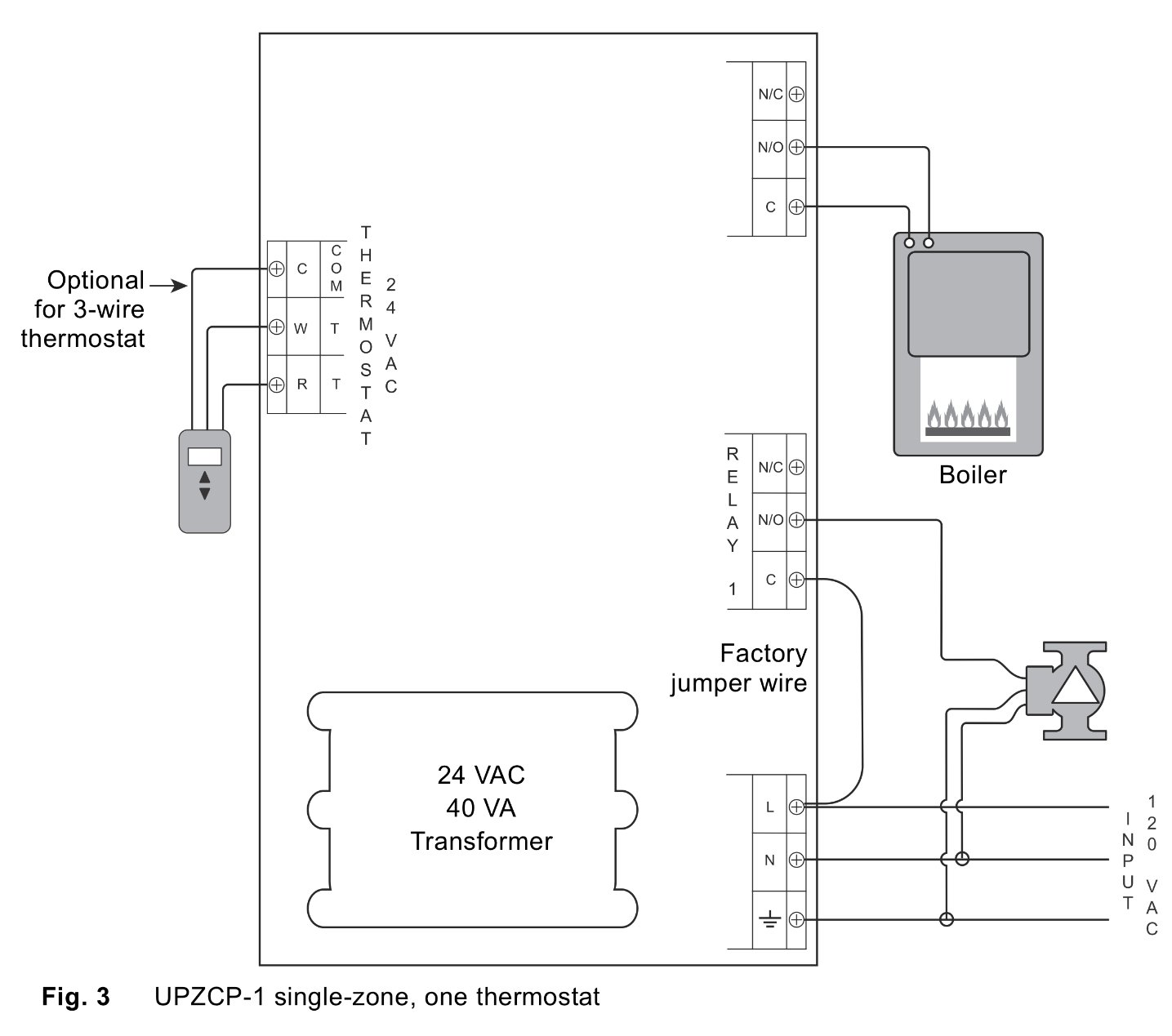
Also included here is the wiring schematic for the relay. I'm particularly concerned about having two transformers in the same system. How can I achieve what I want? Advice would be greatly appreciated!

Comments
-
When 24v is applied to the zone 1 zone valve motor. Also have that 24v energize the coil of a N.O. relay. N.O. contacts close on a heat demand, wire it to TT on the new switching relay for the Grundfos.0
-
If I follow you correctly, the new N. O. relay would be closed (and T-T connected) only when the Zone 1 motor is running. But when the valve is fully open, the Zone motor stops running until it gets a “satisfied” signal from the thermostat. I need the radiant relay to keep the pump going, even though the Zone valve motor has paused while awaiting that signal. Or am I missing something?0
-
If you want the radiant pump to operate the same time as the boiler pump and be controlled by the thermostat on zone 1, which is a Honeywell T87F, then you just wasted $50 on a Grundfos UPZCP-1.
This is the way I would wire your radiant pump to work with the boiler pump. Rather than stress (with two pumps) the Aquastat relay that controls the boiler pump, I would add another relay.
A 115v coil single pole, NO relay (90-291Q White Rodgers) $8.00.
I would wire the W/R 115V terminals to the boiler pump, either at the aquastat or in the boiler pump wire housing and then connect the 115V black & white wire that turns on the boiler pump to the NO terminals on the relay that goes to the radiant pump.
That is: the added radiant W/R relay coil is wired to the NO terminal on Relay 1 and to the N wire on the 120V input. When Relay 1 closes, power is supplied to the W/R relay coil, closing the NO points on the W/R relay . Then the L1 power supplied to the NO point (now closed) goes to the radiant pump and a white (N) wire goes from the radiant pump to the N wire on the 120V input. How you wire it up is up to you it just has to be connect this way.
Screw the W/R radiant relay to the boiler cabinet or whatever.
This will work and save you a ton of money, too. Buy the relay from Supplyhouse.com sku 90-291Q.0 -
"I would wire the W/R 115V (COIL) terminals to the boiler pump,
I hope this is clear. The 115V coil circuit is actuated by the boiler pump turning on, closing the NO points. The 115V's to the NO terminal goes to the radiant pump turning on the radiant pump. The N wire from the radiant pump goes back to the N wire on the 115V input. Simple!0 -
You do need the relay if you want the zone 1 circ to run only with zone 1.
You do want to keep the existing transformer out of the mix.
Wiring the new new relay, t-stat and circ per instructions will work fine.
The relay 2 terminals just need to complete the "T-T" on the boiler. It is not a big deal if it is parallel with the other system as those are just dry contacts (no voltage from the relay).
I really like controllers like that as they clean up wiring and make troubleshooting simple.
Nothing uglier to a spaghetti mess of curly cue wires.
"If you can't explain it simply, you don't understand it well enough"
Albert Einstein0 -
This one would cost about $35 less and you might win an abstract art award....HomerJSmith said:If you want the radiant pump to operate the same time as the boiler pump and be controlled by the thermostat on zone 1, which is a Honeywell T87F, then you just wasted $50 on a Grundfos UPZCP-1.
This is the way I would wire your radiant pump to work with the boiler pump. Rather than stress (with two pumps) the Aquastat relay that controls the boiler pump, I would add another relay.
A 115v coil single pole, NO relay (90-291Q White Rodgers) $8.00.
I would wire the W/R 115V terminals to the boiler pump, either at the aquastat or in the boiler pump wire housing and then connect the 115V black & white wire that turns on the boiler pump to the NO terminals on the relay that goes to the radiant pump.
That is: the added radiant W/R relay coil is wired to the NO terminal on Relay 1 and to the N wire on the 120V input. When Relay 1 closes, power is supplied to the W/R relay coil, closing the NO points on the W/R relay . Then the L1 power supplied to the NO point (now closed) goes to the radiant pump and a white (N) wire goes from the radiant pump to the N wire on the 120V input. How you wire it up is up to you it just has to be connect this way.
Screw the W/R radiant relay to the boiler cabinet or whatever.
This will work and save you a ton of money, too. Buy the relay from Supplyhouse.com sku 90-291Q."If you can't explain it simply, you don't understand it well enough"
Albert Einstein0 -
I read your post 4 times, boy, am I dense. I think I got it.
You have 2 zones that are controlled by 2 Honeywell T87F thermostats + a radiant zone run by a circulator controlled by the thermostat on zone 1. You want the radiant circulator to run only when zone 1 is running and not run when zone 2 is running. OK, this is how I'd do it.
You need the Grundfos relay box, which you have, and you need a separate relay, a White Rodgers Fan Relay, Type 84, 24 VAC Coil, SPNO, #90-290Q (Supplyhouse.com).
You have a conflict between the aquastat transformer running the thermostat and zone valve 1 and the Grundfos tranformer, which is why you need an isolation relay.-- Wiring it up:
The radiant circulator is connected to the Grundfos relay box as is shown in your schematic to relay 1, just make the 115 V connection to the Grundfos relay box with a 16 ga 3 wire pigtail and plug it into a house receptical. Now the 24 V circuit.
First, the Grundfos box side of the circuit. You connect the NO terminals on the White Rodgers relay to the R & W terminals on the Grundfos thermostat 24 Vac.
Second, now, the zone valve 1 side of the circuit. Connect the coil terminals on the White Rodgers relay to the the 1 & 3 terminal screws on zone valve 1. I think that the aquastat transformer current will handle the gas valve, primary pump relay, zone motor and W/R relay coil.
Operation: The zone valve 1 opens and sends 24 Vac from the aquastat transformer to the coil contacts on the W/R relay which closed the NO relay contacts to the R & W terminals on the Grundfos box and which closes Relay 1 NO contacts and activates the Radiant pump. Simple.
0 -
I had assumed zones 2 and 3 were working fine and you are just looking to set up zone one. Correct? If so, my post above will work.
Just be sure it does not look like this when you are done."If you can't explain it simply, you don't understand it well enough"
Albert Einstein0 -
Thanks, HomerjSmith! We're getting close, but we may not be all the way to where I'd like to be.
The remaining problem, I think, is that the two zone valves are jumpered together at terminals 1, 2, and 3. Hence, the Zone 2 valve is going to energize terminals 1 and 3 on the Zone 1 valve, whenever Zone 2 is calling for heat, even if Zone 1 is not also calling for heat. My radiant pump would then sometimes be working when Zone 1 is shut down.
But maybe that is okay (ignoring the waste of energy and unecessary wear and tear), if necessary. Or is it? Your thoughts would be appreciated on that.
Is there some sort of solution that replaces the combined connection to the boiler and the jumpered valve set up?
0 -
Are the valves on zones 2 and 3 both opening when either t-stat calls or did someone just use the terminals to tie together the parallel wiring of the end switches and commons?"If you can't explain it simply, you don't understand it well enough"
Albert Einstein0 -
Hey, Zman, how'd you get a picture of my work?
I don't see how you could control 2 zones with one thermostat and still have the zones work independently. Look, you have 2 Honeywell T87F thermostats, one for each zone valve, right?
Quote:
OK. " As the (zone) valve reaches the full open position, side “B” of the motor switch closes, providing a low voltage auxiliary circuit for starting the burner or circulator." This should be common to both zone valves"-- because each zone valve should be able to turn on the burner and circulator, independently, when there is a call for heat.
Quote:
"TO AUXILIARY CIRCUIT
(NOTE: IF SAME TRANSFORMER POWERS BOTH THE AUXIL-
IARY CIRCUIT (burner & circulator) AND THE WATER (zone) VALVE, CONNECT AUXILIARY CIRCUIT TO TERMINALS 1
AND 3 INSTEAD OF 2
AND 3.)"
The burner and boiler circulator are turned on by screws #3 & #1, which is common to both zone valve 1 & zone valve 2. So, #3 & #1 should be connected in parallel to both zone valves. Power from the aquastat transformer is connected to screw #2 on both zone valves, so you can say that screw #2 is also in common to both zone valves, like you said. Whether a zone valve is operating or not operating is dependent on the thermostat. So, if zone valve 2 is not operating and zone 1 is operating the radiant pump will turn on. If zone valve 2 is operating and zone valve 1 is not operating, then the radiant pump would be off. The reason this is so, is because the thermostat for zone 1 hasn't energized the motor in zone valve 1 and made the contact for the "OPEN POSITION SIDE 'B' ". Therefore, no current flows to the coil contacts on the W/R isolation relay.
The connection to the W/R coil contacts should be from screws #3 and #1 on zone valve 1. I think I got this right.0 -
The real concern is the current draw on the aquastat transformer, it is probably 40 VA as that seems to be the standard. Add up the VA of all the current users when everything is operating and it should be less VA than the rating of the transformer. If not, you would need to connect up an auxiliary transformer in parallel with the aquastat transformer. AN IMPORTANT NOTE: Both the aquastat and auxiliary transformer connected in parallel must be in phase. There is a way to do this.0
-
Big Picture—just to help clarify things: the entire house is divided into two zones. Years ago a family room (with fin and tube) was added to the house, knocking out the entire back wall of the kitchen. Since this left the kitchen without any place for a radiator, none was reinstalled. Heat from the family room area was expected to be adequate to satisfy both areas.
In the course of now redoing the kitchen, I decided to supplement the heat with a Warmboard radiant floor in the kitchen area. The thermostat for this part of the house (Zone 1) is located near where the original back wall had been, essentially in the middle of this now combined kitchen/family room.
The new radiant floor taps into the return line from the family room, and it works just fine. My goal is to hook up the controls so that the floor (specifically, the radiant circulator) operates in sync with the family room emitters as part of Zone 1, controlled by the existing thermostat that currently controls the family room. I am not intending the floor to operate independently of the family room (I.e., as a Zone 3). I just want the one thermostat to control the kitchen and family room as one, single heating area.
Hope this puts the challenge in better perspective! I appreciate all your attention to helping to find a solution.
To answer Zman's question, the burner and main pump come on when the thermostat in either (or both) of the zones is calling for heat. However, each zone valve opens only when it’s own thermostat is calling for heat. The jumpers between the two valves are strictly there to feed the transformer power to both valves (and their thermostats) and to combine the wiring that runs from the valves over to the relay on the boiler.0 -
What is it about my solution that you don't understand?
I addressed your concerns about the two zone valve having wiring in parallel. I am only concerned about the radiant floor operating with zone 1 and not zone 2. I gave you that solution.
I am open to any criticism of my solution.0 -
I was thinking about Zman's post and solution and he probably has something there. Using his thoughts, it could be wired this way without the W/R isolation relay.
Wire this way--
Connect the Honeywell T87F zone 1 thermostat to the R & W terminals on Grundfos relay box. Then connect the NO & C terminals on Relay 2 in the Grundfos box to the #5 & #4 screws on zone valve 1. Thanks, Zman. I think this is probably the best hookup as it eliminates the current draw of the W/R isolation relay.
I guess there is more than one way to skin a cat, although I have never done that nor do I know anyone who has.
Case solved by Zman!0 -
@HomerJSmith
Thank you for the kind words and humor.
That Dayton diagram is one of the more confusing I have seen. I think that in reality it is just a standard 4 wire zone valve. (motor and end switch)
"If you can't explain it simply, you don't understand it well enough"
Albert Einstein0 -
It is really a White/Rodgers Type 1361 valve.
 -1
-1 -
Thanks guys. Let me study Zman's comments further. In the meantime, if the suggestion is to wire the new relay (which then triggers the Grundfos relay) to Terminals 1 and 3, It appears to me that the radiant pump would run whenever the Zone 2 valve is open and calling for heat. Here is a crude sketch of the circuits when Z1 is closed and Z2 is open, the green path for the boiler and the yellow for the radiant pump.

0 -
REKBDR--Quit already, it's been solved and stop worrying about zone 2. It will all operate the same as before. The only difference is that the thermostat operates the Grundfos box instead of the zone 1 valve. Read below.
Wire this way--
Connect the Honeywell T87F zone 1 thermostat to the R & W terminals on Grundfos relay box. Then connect the NO & C terminals on Relay 2 in the Grundfos box to the #5 & #4 screws on zone valve 1. Thanks, Zman. I think this is probably the best hookup as it eliminates the current draw of the W/R isolation relay.
0 -
Look, REKBDR, just wire it up the way you were told and if you have a problem and your house burns down you can call Zman or reach me in my office in Romania.1
-
Hmmmm...... what happened to “I am open to any criticism of my solution”?
Here is where I think we stand.
The original approach was to figure out a way to have the Zone 1 valve control the radiant pump (either directly or via a Grundfos relay). This was unsuccessful because it relied on Terminals 1 and 3, which would also be energized by the Zone 2 valve, or because it was based directly on the operation of the main pump, which again meant that the radiant pump would on when Zone 2 was on, even if Zone 1 was off.
Zman’s idea is to use the Grundfos relay to control the Zone 1 valve (along with the radiant pump) by wiring it midway between the thermostat and the zone valve.
Currently under study is the “wire this way” plan:
“Connect the Honeywell T87F zone 1 thermostat to the R & W terminals on Grundfos relay box. Then connect the NO & C terminals on Relay 2 in the Grundfos box to the #5 & #4 screws on zone valve 1.”
Maybe I am missing something that is implicit in this plan, but I don't see how the “satisfied” signal from the thermostat gets to the Zone 1 valve in order to rotate the valve to the closed position. Under this set up, the power running through the thermostat comes from the transformer in the Grundfos relay box, and Relay 2 controls just the circuit that includes Terminals 5 and 4 on the valve (which are powered by the existing transformer near the valve). If I keep in place the existing line from the thermostat directly to Terminal 6, am I facing a problem with two transformers feeding the valve (through the thermostat? If I disconnect all of the lines that currently run directly between the thermostat and the valve (I.e., Terminal 6 as well as 5 and 4), how does the valve close when the time comes?0 -
Ok, Here's the deal. The Grundfos relay will run your new zone 1. That's what is designed to do and it will work if wired per instructions.
Your boiler will run anytime something closes the "T-T" terminals. It provides power to one terminal and waits to get it back on the other. It is just looking for a switch to close. The Grundfos has a switch on relay 2 and your zone valves have end switches that should not be powered by the t-stat, they should just be switches that get connected to the boiler so it knows to start. It is just like the light switch. If you turn it on, you complete the circuit between the power source and the load and it works.
"If you can't explain it simply, you don't understand it well enough"
Albert Einstein0 -
REKBDR--No, no, no--That is not correct. If you were to use an isolation W/R relay and connect it to screw 3 & 1. Zone 2 operating would have no effect on whether the radiant circulator would run or not. The parallel wiring between zone 1 and zone 2 doesn't mean that zone 2 will control the radiant pump. Look at the switching mechanism on side B open position on zone 1as to why zone 2 would have no effect on the operation of the radiant pump. I have, I think, already explained this. But, the latest way to connect everything, thanks to the insight of Iman, is to not use a isolation relay and allow the Grundfos box to control the zone 1 valve. If you were to use the isolation relay then the zone 1 valve would control the Grundfos relay box and therefore the radiant pump.
Criticism has to be factually based, so tell me why you think that zone 2 would turn on the radiant pump when zone 1 is off and forget the parallel wiring. Take a volt meter and touch screw 1 & 3 and read the voltage when zone 1 is running and then then zone 2 is running and zone 1 is off. Report back.
0 -
"If I keep in place the existing line from the thermostat directly to Terminal 6, am I facing a problem...?"
REKBDR--That is a very perceptive question and am I glad you brought that up. That may change my analysis.
There are two schematics for the W/R 1361 zone valve. Your schematic shows a three wire zone valve and a three wire thermostat. The Honeywell T87F can be either a 2 wire or 3 wire configuration. It has a 4 digit number after the F, what is it? The schematic that I was looking at was a 2 wire thermostat zone valve.
Do you have a #6 screw on zone 1 valve and is a wire connected to it? If so, you then have 3 thermostat wires connected to zone 1 valve, #4, #5, and #6 screws. Is this true?
I need to know this before I can proceed further.0 -
The 3 wire zone valve is a White/Rodgers Type 1311. The Honeywell T87F sub-base determines whether the thermostat is 2 or 3 wire.0
-
If you have this scenario ("Do you have a #6 screw on zone 1 valve and is a wire connected to it? If so, you then have 3 thermostat wires connected to zone 1 valve, #4, #5, and #6 screws. Is this true?") and your answer is Yes then--
Wire it this way:
First, the Honeywell T87F thermostat must operate as a 2 wire thermostat and not a 3 wire thermostat. Later about that if you confirm that the zone 1 valve is a 3 wire connection to the thermostat.
Secondly, wire the Grundfos box to zone 1 valve as follows:
You need a 3 conductor 18 ga thermostat wire, long enough to span the distance between the Grundfos box and zone 1 relay.
The wire insulation colors are usually red, white, and green or blue. If you only have 4 conductor, just don't use one colored wire.
It is important to wire exactly like this.
The C terminal on Relay 2 on the Grundfos box is connected with the red wire to screw #5 on zone 1 valve. The NO terminal on Relay 2 on the Grundfos box is connected with the white wire to screw #4 on zone 1 valve. The NC terminal on the Grundfos box is connected with the green wire to screw #6 on zone 1 valve. Simple.
Sequence of operation:
When the thermostat call for heat the Grundfos relay 2 is activated the switch moves from a NC position to the NO position, closing NO and C. The current moves from the transformer to screw #2 thru screw #5 thru the red wire to terminal C thru NO thru the white wire to screw #4. This makes a circuit and the motor rotates 90 degrees opening the valve.
When the thermostat is satisfied, relay 2 on the Grundfos box is de-energized and the relay move to the NC position and the NC and C terminal are connected. The current moves from the transformer to screw #2 thru screw #5 thru the red wire to terminal C thru NC thru the green wire to screw #6 thru the motor winding to screw #1 completing a circuit and the motor rotates 90 degrees and closes the valve.
I'm truly sorry for the mix up as I was looking at a 2 wire zone valve schematic and not a 3 wire zone valve schematic. Thank you for pointing that out.
As far as the Thermostat is goes, if it is 3 wire, connect from R to R and W to W on the Thermostat and Grundfos box and forget about the extra wire.0 -
Connect the radiant pump to Relay 1 on the Grundfos box as previously posted and connect the power to the Grundfos box as previously posted.0
-
I am happy to say that I think you have done it, HomerjSmith! Thanks, too, to Zman for heading us in the right direction.
Here is a diagram of what I understand to be the final wiring. The thermostat is currently a three wire setup, but I will remove the third wire from operation. The Zone 2 set up will remain as currently configured, with the jumpers for Terminals 1, 2, and 3.
As I trace through the circuitry, it looks like this does the trick. Let me know if I have screwed up anything.
Again, thanks for all your help—and patience!
0 -
Yup! Sorry about getting fixated on a 2 wire system.0
-
The only thing is that the gas valve and aquastat circulator relay should if I read the schematic note correctly be connected to screws #3 and #1. Might want to check that out.0


Categories
- All Categories
- 87.7K THE MAIN WALL
- 3.3K A-C, Heat Pumps & Refrigeration
- 59 Biomass
- 431 Carbon Monoxide Awareness
- 127 Chimneys & Flues
- 2.2K Domestic Hot Water
- 5.9K Gas Heating
- 121 Geothermal
- 170 Indoor-Air Quality
- 3.8K Oil Heating
- 79 Pipe Deterioration
- 1K Plumbing
- 6.6K Radiant Heating
- 396 Solar
- 16K Strictly Steam
- 3.5K Thermostats and Controls
- 56 Water Quality
- 51 Industry Classes
- 51 Job Opportunities
- 17 Recall Announcements