Welcome! Here are the website rules, as well as some tips for using this forum.
Need to contact us? Visit https://heatinghelp.com/contact-us/.
Click here to Find a Contractor in your area.
If our community has helped you, please consider making a contribution to support this website. Thanks!
wrong side of the 3-way
Options
GW
Member Posts: 5,188
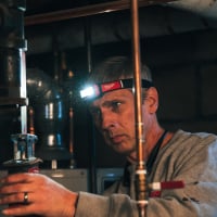
just got emailed this pic, look like a problem to you all?
0
Comments
-
Looks like it's installed in a diverting configuration. I can't see where the piping goes, but if it's factory piped like that, then it should be right.
Is it a Viega?Bob Boan
You can choose to do what you want, but you cannot choose the consequences.
 2
2 -
I can't tell by that picture which way the pump is flowing. I hope it's to the right.0
-
according to the arrows on the valve it's a diverting valve (1 inlet, 2 outlets). The pump should be pumping to the right. Zone to the right heat source to the left
The bigger question is where is the temperature sensor running the valve? (if any)0 -
Yes it looks like a Viega, I was thinking the valve is backwards. You can't pump in to a mixing valve
 1
1 -
Looks like a:
DIVERTING (judging by the arrows) valve which is 1 inlet and 2 outlets. A diverting valve sends water through the heater (coil, baseboard or whatever) or bypasses the flow into the return line. Diverting valve mounts in the supply line to the heater.
MIXING valve has 2 inlets and 1 outlet. Mixing valve gets bypassed water from a tee cut into the heater supply into 1 inlet and return water from the heater into the other inlet. The common port is returned to the boiler. Mixing valve mounts in the return line from the heater 1
1 -
Looks OK to me. It's a Viega circulator, diverting valve, and manifold. As long as that circ is pumping left to right (into the valve), should be fine. The upper manifold with the blue knobs is the return, and that flow should go through the circ and into the diverting valve. The upper insulated pipe in photo should go back to boiler, the lower one come in hot from the boiler. If that's the case you're OK. The temp sensor in the lower left of the photo is measuring the mixed temp, and is in the right spot if that's the input the tekmar control uses to drive the diverting valve.0
-
that is a proper configuration for a viega manifoldCost is what you spend , value is what you get.
cell # 413-841-6726
https://heatinghelp.com/find-a-contractor/detail/charles-garrity-plumbing-and-heating0 -
Right on I've always used mixing valves0
-
GW said:
Right on I've always used mixing valves
It depends on the design and internals of the valve.
A typical off the shelf thermostatic valve, that you are familiar with, when used for radiant mixing would require the circ on the AB port pumping away.
Basically a circulators goal is to get all the flow going out the discharge, back to the inlet side:) the least restrictive flow path. Add to that the pressure drop that radiant loops present to the mixed port. So the majority of the flow goes across the cartridge from A to B.
Pumping awayat the AB port pulls flow through the valve from both A&B or H&C ports and also assures good flow around the thermostatic, wax cartridge inside so it can respond accurately.
This is the reason three way thermostatic valves have a minimum flow required for stable temperature operation, below . 5 gpm the wax cartridge inside doesn't get turbulent flow around it to evenly heat up and move the "internals"
Catch 22, thermostatic valves are very restrictive and ideally you don't want to put any flow restrictive device at the suction side of a circulator, watch the Cv number, try to size the valve (Cv number) at or close to the gpm you will flow.
Commonly mis-applied, installers buy the 3 cv valve and try to pull 6, 8 or more GPM, huge pressure drop through the valve at high flow rates, so high head circs are often required to both flow the valve and loops adequately.
Bob "hot rod" Rohr
trainer for Caleffi NA
Living the hydronic dream0


Categories
- All Categories
- 87.7K THE MAIN WALL
- 3.3K A-C, Heat Pumps & Refrigeration
- 59 Biomass
- 430 Carbon Monoxide Awareness
- 127 Chimneys & Flues
- 2.2K Domestic Hot Water
- 5.9K Gas Heating
- 121 Geothermal
- 170 Indoor-Air Quality
- 3.8K Oil Heating
- 79 Pipe Deterioration
- 1K Plumbing
- 6.6K Radiant Heating
- 396 Solar
- 16K Strictly Steam
- 3.5K Thermostats and Controls
- 56 Water Quality
- 51 Industry Classes
- 51 Job Opportunities
- 17 Recall Announcements