Welcome! Here are the website rules, as well as some tips for using this forum.
Need to contact us? Visit https://heatinghelp.com/contact-us/.
Click here to Find a Contractor in your area.
If our community has helped you, please consider making a contribution to support this website. Thanks!
How can I increase flowrate of existing insalled system zone?
Options

Wasko
Member Posts: 1
Hi,
New to site, great information. I've been doing a lot of searching the site on circulating pumps, with flow rate and head loss. I think I've figured out my issue so I'm looking for confirmation and any ideas to solve the issue.
With the help of a retired hydronic plumber, we designed the system together. I installed the system and built the disbtribution panel based on my helpers input. I still have ALL the drawings and calculations that we used. We used the Heataway software for the loads and sizing and,yes there is ONIX tubing stappled up .
It's a 4 zone system:
Z1-->1/2" Al-Pex in 6" concete, 3 circuits, 295', 295' 265', --> 13000 Btu/h panel load, 1GPM
Z2--> 3/8" Onix stappled under floor, 5 circuits, 200',182',182',170',170', 4900 Btu/h panel load, .3GPM
Z3--> 3/8" Onix stappled under floor, 6 circuits, 176',176',170',160',125',125', 6200 Btu/h panel load, .5 GPM
Z4--> HW coil in a former HVAC Oil burner for the older side of the house.
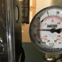
The boiler is a WM WTGO-4, with a hot water coil, feed by a 40 gallon electric hot water heater set at 80 Deg F. We are on well water. At the time I built the hose, generators expensive, the HW tank used as backup to flush when power went out, which was often, back then, not too often now. I do have backup generator now. I changed the anode twice and the tank has just stayed around. I have attached my hand drawn schematic and a marked up picture of what of what I'm about to ask.
The system has worked well and given us years of comfort in the winter. Maybe not the most efficient. Zones 1, 2, and 3 have copper manifolds with only ball valves on the returns for balancing. I balanced the sysem based on delta T of each loop. The system was designed for 20 deg F, delta T. The supply water temp to all the zones was a comromise, the concrete wanted 84 deg F,but the stapple up needed 106 deg F. From the schematic you see a Danfoss RAVV valve that sets the temperature of all the zones to 106 degree. System works well. No flow meters until just 2 weeks ago.
The L2184 aquastat took a hit in September, no DHW. I replaced it whit a programmable 7224U. It has a temp reset option so I added the outdoor , so decided to try to save oil and make system more efficeint. Then replaced Z3 manifold with SS one with actuators, flow meter, air vents, and temperature gage, very nice compared to what was around in 1997.
I was always troubled by the fact I could never get the delta Temp of Z3 better than 32 degrees. I never gave it much thought, it was concrete and different from the staple up stuff. I installed the new 3-circuit manifold with flow meters. Start the system, bleed each circuit of air. Turn on all the circuits, suprise to me, there is no reading on the flow meters (.25 to 1.6 GPM are markings), not even water in the slow tubes. The schematic is attached. I then shot the actuators, just vent the manifold, used 1/2 gallon milk jug to calibrate the flow, but open to the atmosphere, with or without Z2/Z1 active, the same .2 GPM.
I've been reading on head loss and GPM the past several weeks, made some calls to local heating plumbers asking if I could get them to consult for a couple hours, no takers. I thought the problem was the 1/2" 300fot of pex, but that only has a head loss of about 9ft, well within the NRF-22 But when I just used the bleed valve, with actuator turned off, I realized the issue is the flow to the manifold. There is about 12' of 3/4" copper pipe from output of pump to manifold, 2-90 and 2-45. the gravity flow valve, and the ball valve. The pumps are all NRF-22. I swopped two of the pumps, same issue, so it's not the pump. I've concluded the issue is not with pushing the water, but there is not enough water to push,the pump is starving for water. I'm thinking I built the control panel with the 3 pumps too close to each other or something. From the pic, you can see a boiler drain valve at the end. Never opened it to when I swopped the pumps, but water pulses out of that while Zones are active. Z3 is at the end of the row, so I think it's starving.
Also note B11, when the system was built, this was suppose to be used for mising with the RAVV, but I recall the designer also talking about pressure differentuals when zones were active at different. I open B11 all the way, RAVV can't get to 106, just to test, and still same problem.
Long story, sorry, tried to get all hights. My thinking is to add a 3/4" run/loop just below where all 3 pumps are feed, and connecting it into where the boiler drain is now, trying to make available the full 4PGM of 3\4" copper pipe to the pumps. More thinking on my part, water takes path of least resistance, more flow to Z3, but what about Z2. I want to update the Z1 and Z2 next, so I'll probably find something there as well.
Any ideas would be appreciated, or if someone would like to consult, I willing to go that route as well. Thanks,
Bob
New to site, great information. I've been doing a lot of searching the site on circulating pumps, with flow rate and head loss. I think I've figured out my issue so I'm looking for confirmation and any ideas to solve the issue.
With the help of a retired hydronic plumber, we designed the system together. I installed the system and built the disbtribution panel based on my helpers input. I still have ALL the drawings and calculations that we used. We used the Heataway software for the loads and sizing and,yes there is ONIX tubing stappled up .
It's a 4 zone system:
Z1-->1/2" Al-Pex in 6" concete, 3 circuits, 295', 295' 265', --> 13000 Btu/h panel load, 1GPM
Z2--> 3/8" Onix stappled under floor, 5 circuits, 200',182',182',170',170', 4900 Btu/h panel load, .3GPM
Z3--> 3/8" Onix stappled under floor, 6 circuits, 176',176',170',160',125',125', 6200 Btu/h panel load, .5 GPM
Z4--> HW coil in a former HVAC Oil burner for the older side of the house.
The boiler is a WM WTGO-4, with a hot water coil, feed by a 40 gallon electric hot water heater set at 80 Deg F. We are on well water. At the time I built the hose, generators expensive, the HW tank used as backup to flush when power went out, which was often, back then, not too often now. I do have backup generator now. I changed the anode twice and the tank has just stayed around. I have attached my hand drawn schematic and a marked up picture of what of what I'm about to ask.
The system has worked well and given us years of comfort in the winter. Maybe not the most efficient. Zones 1, 2, and 3 have copper manifolds with only ball valves on the returns for balancing. I balanced the sysem based on delta T of each loop. The system was designed for 20 deg F, delta T. The supply water temp to all the zones was a comromise, the concrete wanted 84 deg F,but the stapple up needed 106 deg F. From the schematic you see a Danfoss RAVV valve that sets the temperature of all the zones to 106 degree. System works well. No flow meters until just 2 weeks ago.
The L2184 aquastat took a hit in September, no DHW. I replaced it whit a programmable 7224U. It has a temp reset option so I added the outdoor , so decided to try to save oil and make system more efficeint. Then replaced Z3 manifold with SS one with actuators, flow meter, air vents, and temperature gage, very nice compared to what was around in 1997.
I was always troubled by the fact I could never get the delta Temp of Z3 better than 32 degrees. I never gave it much thought, it was concrete and different from the staple up stuff. I installed the new 3-circuit manifold with flow meters. Start the system, bleed each circuit of air. Turn on all the circuits, suprise to me, there is no reading on the flow meters (.25 to 1.6 GPM are markings), not even water in the slow tubes. The schematic is attached. I then shot the actuators, just vent the manifold, used 1/2 gallon milk jug to calibrate the flow, but open to the atmosphere, with or without Z2/Z1 active, the same .2 GPM.
I've been reading on head loss and GPM the past several weeks, made some calls to local heating plumbers asking if I could get them to consult for a couple hours, no takers. I thought the problem was the 1/2" 300fot of pex, but that only has a head loss of about 9ft, well within the NRF-22 But when I just used the bleed valve, with actuator turned off, I realized the issue is the flow to the manifold. There is about 12' of 3/4" copper pipe from output of pump to manifold, 2-90 and 2-45. the gravity flow valve, and the ball valve. The pumps are all NRF-22. I swopped two of the pumps, same issue, so it's not the pump. I've concluded the issue is not with pushing the water, but there is not enough water to push,the pump is starving for water. I'm thinking I built the control panel with the 3 pumps too close to each other or something. From the pic, you can see a boiler drain valve at the end. Never opened it to when I swopped the pumps, but water pulses out of that while Zones are active. Z3 is at the end of the row, so I think it's starving.
Also note B11, when the system was built, this was suppose to be used for mising with the RAVV, but I recall the designer also talking about pressure differentuals when zones were active at different. I open B11 all the way, RAVV can't get to 106, just to test, and still same problem.
Long story, sorry, tried to get all hights. My thinking is to add a 3/4" run/loop just below where all 3 pumps are feed, and connecting it into where the boiler drain is now, trying to make available the full 4PGM of 3\4" copper pipe to the pumps. More thinking on my part, water takes path of least resistance, more flow to Z3, but what about Z2. I want to update the Z1 and Z2 next, so I'll probably find something there as well.
Any ideas would be appreciated, or if someone would like to consult, I willing to go that route as well. Thanks,
Bob

1
Comments
-
I don't have access to the pump curves -- which would be really helpful. However, from my reading of your sketch (correct me if I'm wrong on this) the Z3 takeoff is closest to the return loop, so if anything is getting water, it should be -- which doesn't sound like what your are describing. Rather my impression is that somewhere in that circuit, in a section of it common to all six circuits, there is a flow restriction or, just possibly, some reason why only one or two of the circuits are flowing, but I would think that that would be obvious. It could be a valve not opening all the way (or even opening only slightly). It could be a kink. It could be...
I must admit I'm not much of a fan of ball valves for throttling or balancing; they really aren't meant for that (nor are gate valves).
I'd look for a restriction somewhere... which is pretty vague, but the best I can do from where I sit!Br. Jamie, osb
Building superintendent/caretaker, 7200 sq. ft. historic house museum with dependencies in New England0 -
Have you looked at the CV values on the RAVV and the gravity check valves? It looks like you have some hidden resistance somewhere.
A couple other thoughts...
The common header for the zone circs and returns should be designed for about 2 ft/sec. Somewhere around 1 1/4" would be more appropriate. The piping back to the boiler loop could be 1".
Your circulators have pretty flat curves. They are not ideal for higher head radiant loops. Theoretically they should work just fine. As you are discovering if your resistance curves end up being steeper that expected, the performance of flat curve circs falls off rapidly.
Carl"If you can't explain it simply, you don't understand it well enough"
Albert Einstein0 -
I agree with Carl on the secondary piping that it should be increased to 1 1 /4 ,I would also think about maybe using a 3 port mixing valve for your slab zone and get a taco I series valve for the 2 other zones .The taco valve can also give you return temp protection.I would have never set it up using that ravv it would have been better to do a injection pump set up with a cross over bridge piping and then use one set 3 way for slab radiant and have the staple up temp be controlled by the injection pump ,There s a lot of ways to skin a cat if your gonna try and run it the way it is I would start by checking RAVV and make sure it s not gunked up .Looking at your photo That b11 I would gather it should be open and I guess they thought they would throttle supply thru the valve as the sensor bulb required .I see this as not even close to the correct way to lower temps for radiant you should contact some one who is familiar w radiant .Also a 30 degree temp diff on radiant is the indication of issues like no slab insulation or long loops or way undersized pumps which I don t really see ,I have a oxion staple up in my home I run it at max temp 140 at 14 outside temp with about a 5 to 10 degree temp diff using a grunfos 15 58 .I think your set up may work but not as it should and is most likely costing you more to operate then it really should .I really have never seen any one do a mixing set up like you got ,Peace and good luck clammy
R.A. Calmbacher L.L.C. HVAC
NJ Master HVAC Lic.
Mahwah, NJ
Specializing in steam and hydronic heating0


Categories
- All Categories
- 87.7K THE MAIN WALL
- 3.3K A-C, Heat Pumps & Refrigeration
- 59 Biomass
- 430 Carbon Monoxide Awareness
- 127 Chimneys & Flues
- 2.2K Domestic Hot Water
- 5.9K Gas Heating
- 121 Geothermal
- 170 Indoor-Air Quality
- 3.8K Oil Heating
- 79 Pipe Deterioration
- 1K Plumbing
- 6.6K Radiant Heating
- 396 Solar
- 16K Strictly Steam
- 3.5K Thermostats and Controls
- 56 Water Quality
- 51 Industry Classes
- 51 Job Opportunities
- 17 Recall Announcements