Welcome! Here are the website rules, as well as some tips for using this forum.
Click here to Find a Contractor in your area.
If our community has helped you, please consider making a contribution to support this website. Thanks!
Air in Oil - Can the pump be bad?
Comments
-
Re: CAD cell … one of my rentals would nuisance lock out, and the CAD cell was floating about 1800 ohms. Combustion was excellent, so I replaced the CAD cell, cleaned and tightened the CAD cell plugs, carefully cleaned the retention head, the air tube, made sure the CAD cell was mounted properly to look down the tube, etc., but it kept floating at lockout.
What I found was the small gull wing bracket that held down the two electrodes at the ceramic barrels with the long center screw had sagged over many years of tightening (and overtightening) when servicing. It still held down the electrode insulators like it should, but the sag in the middle of the bracket where the screw went through got in the line of sight with the CAD cell and the flame and blocked most of it. I took the bracket out and pounded it straight. The resistance dropped to below 500 ohms.
 1
-
@NJeffro , what did you disconnect to open the boiler door to clean it? Does the door swing with the braided oil lines so nothing needs disconnecting on the oil side? Could there be a cracked fitting? Have you gone over carefully all the steps from the original nozzle replacement and cleaning? All the wiring is secure in the primary? Clean out door on the boiler is evenly tight?
On the L2 head there's 3 brackets. The top bracket needs to be at 12 o'clock, between the two holes in the nozzle assembly so the eye can see the flame.
Since you replaced the fuel pump, its now firing at 100 psi? If so, that throws everything off.
I wouldn't think the OSV is closed because once its running, it runs.
0 -
THE OSV may be sticking requiring excess vacuum to open.
0 -
The EnviraCom cable to the primary control, and the burner power plug.
Right, flex lines, no need to disconnect copper.
The brackets are positioned as you said.
I have a pressure gauge. Deadheaded onto the nozzle line, set pressure to 150 per manufacturer spec.
I don't believe it's the OSV either.
 1
-
Vacuum gauge shows 1.5 - 2 " of vacuum.
0 -
150 psi. So the burner is pre March 2013. Air settings S-6/B-0 to start with? The low fire baffle is installed?
0 -
On Oct 12 @MaxMercy said "I've been following and not commenting since I don't know what's going on, but I do have a question and then a comment. OP mentioned several times that there's no sign of air/bubbles/foam in the TL. I have NEVER seen a TL ever, so I confess that I don't know how they work, but my question is that -"
Here is how the tiger loop works.
Lets start new with no oil in the TL
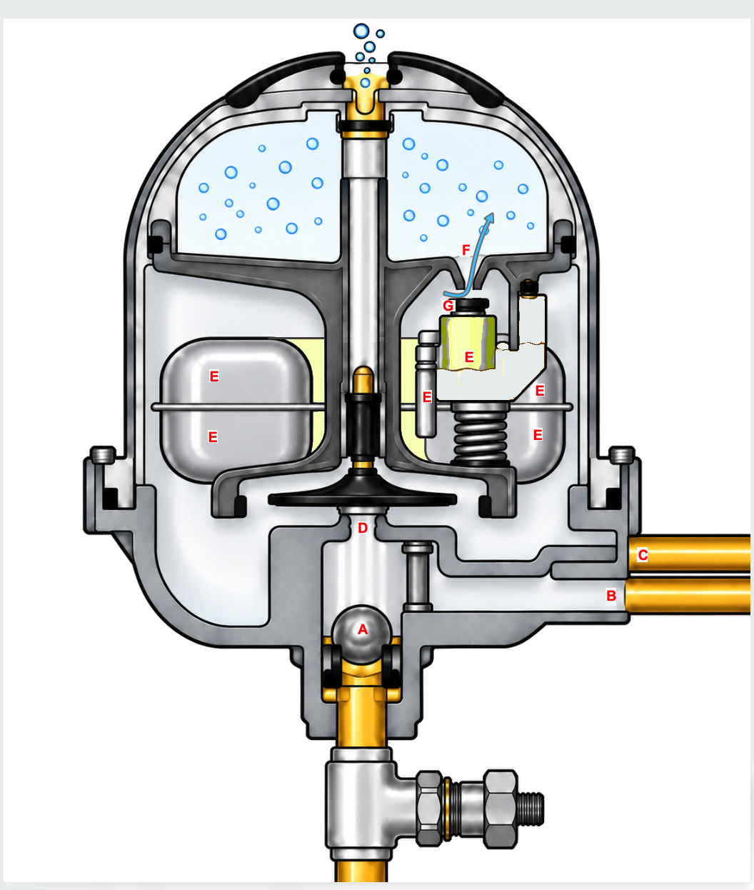
Float E is at the lowest point and that leaves Port F open from the Central chamber to the upper chamber so air can vent. The valve seat covering Port D is closed so the path from the tank to the fuel pump is sealed and the ball check A is closed.
When the pump operates a vacuum happens on the inlet of the pump. That vacuum thru port B opens the ball check A and oil from the tank is drawn into the pump thru the bottom chamber of the TL
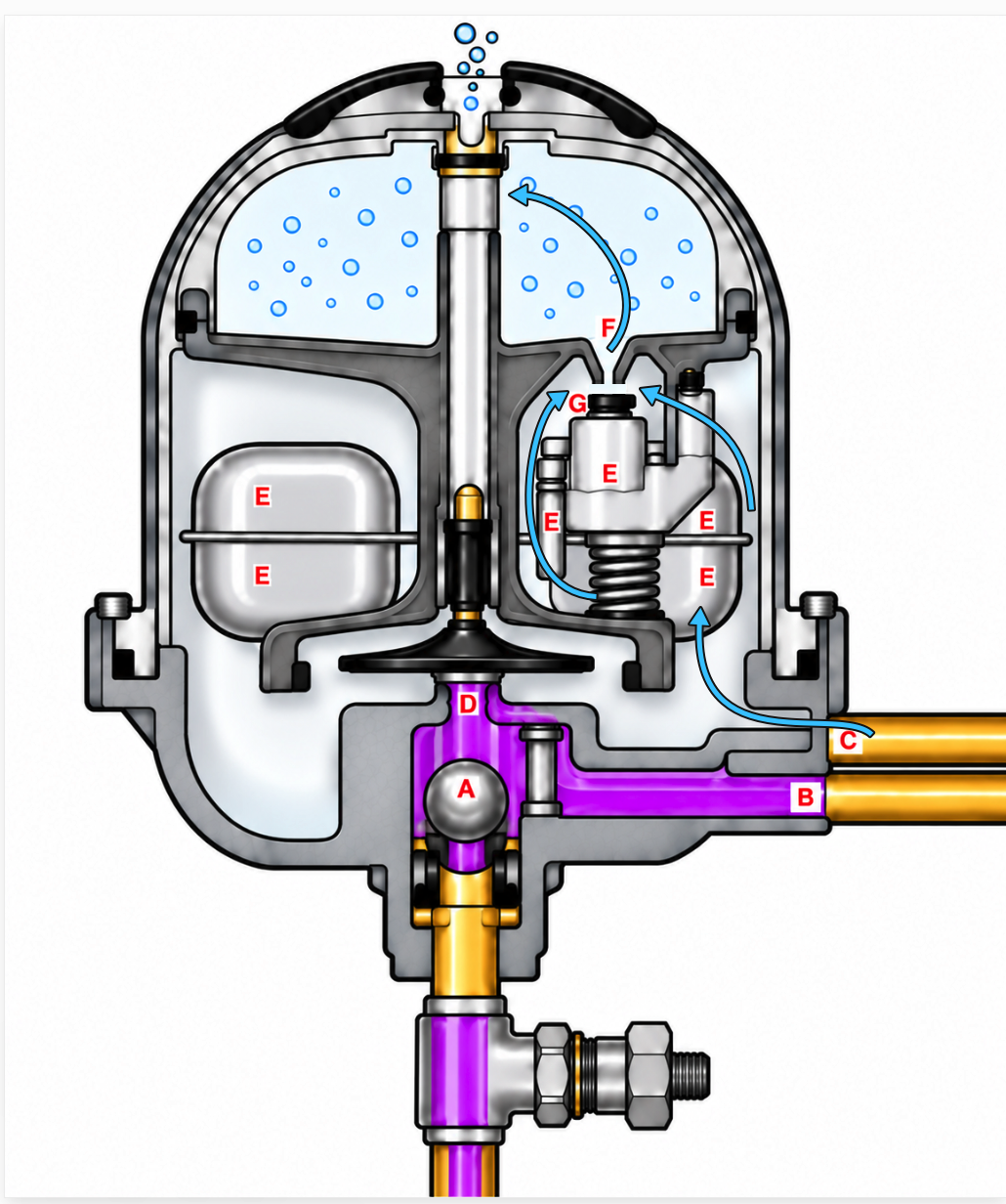
Air in the fuel line system is then driven out the pump's return line to port C of the tiger loop. The air vents thru port F of the TL from the Center chamber to the upper chamber where is is vented to the atmosphere.
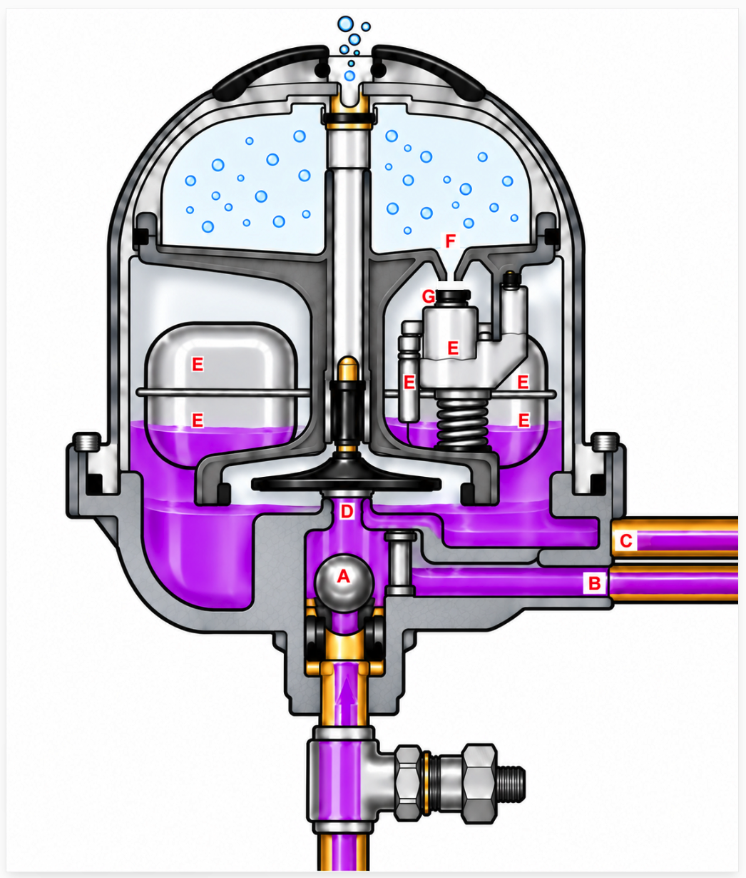
Once oil is returned to the TL from the fuel pump it enters the center chamber and the float E raises to cut off port F with valve seat G.
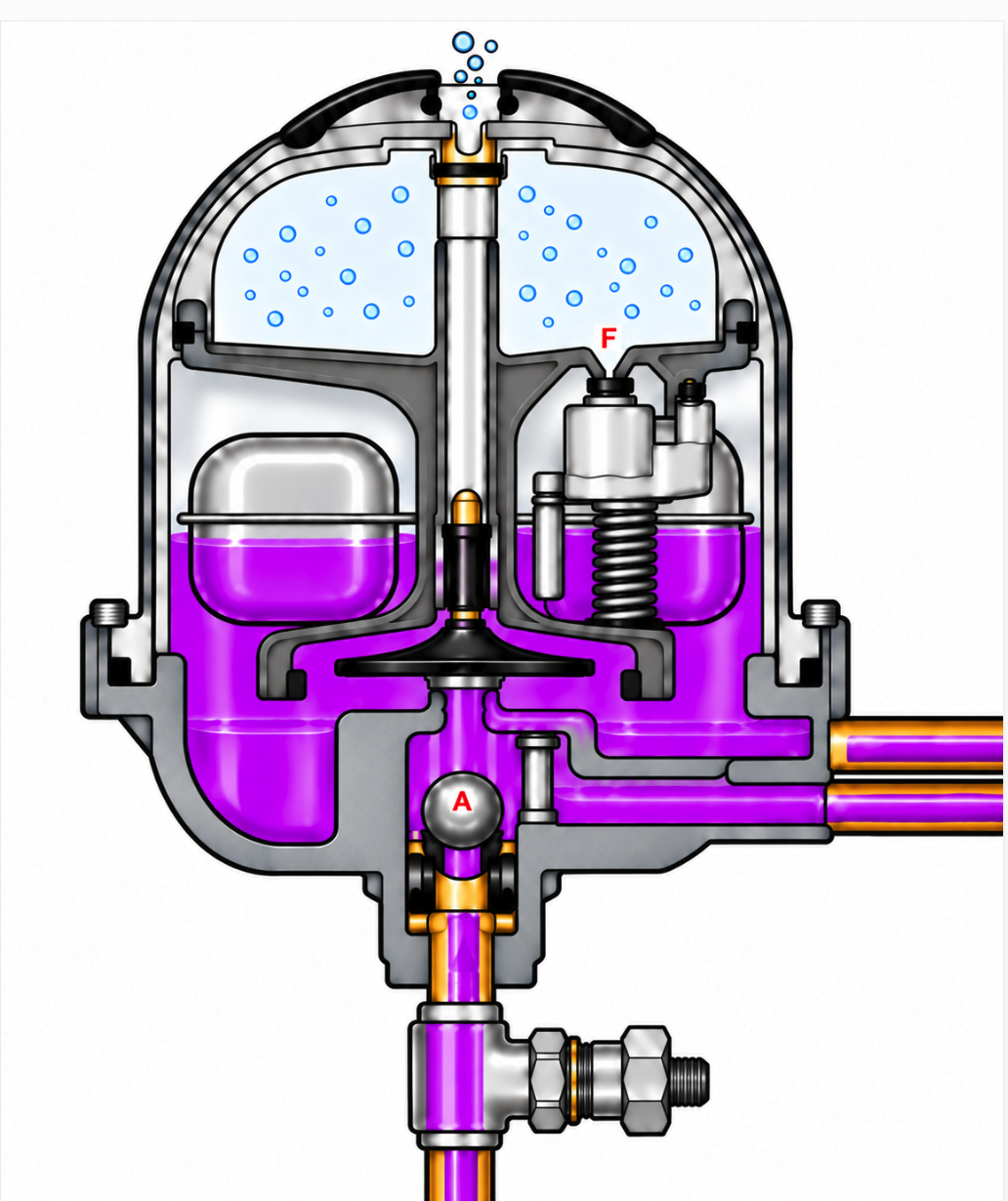
With port F closed the oil begins to build up pressure in the center chamber of the TL. when the pressure reaches about 1.5 PSI that forces valve seat D to open and allow fuel from the center chamber into the lower chamber so it can pass to the pump thru port B. That oil can return to the pump inlet.
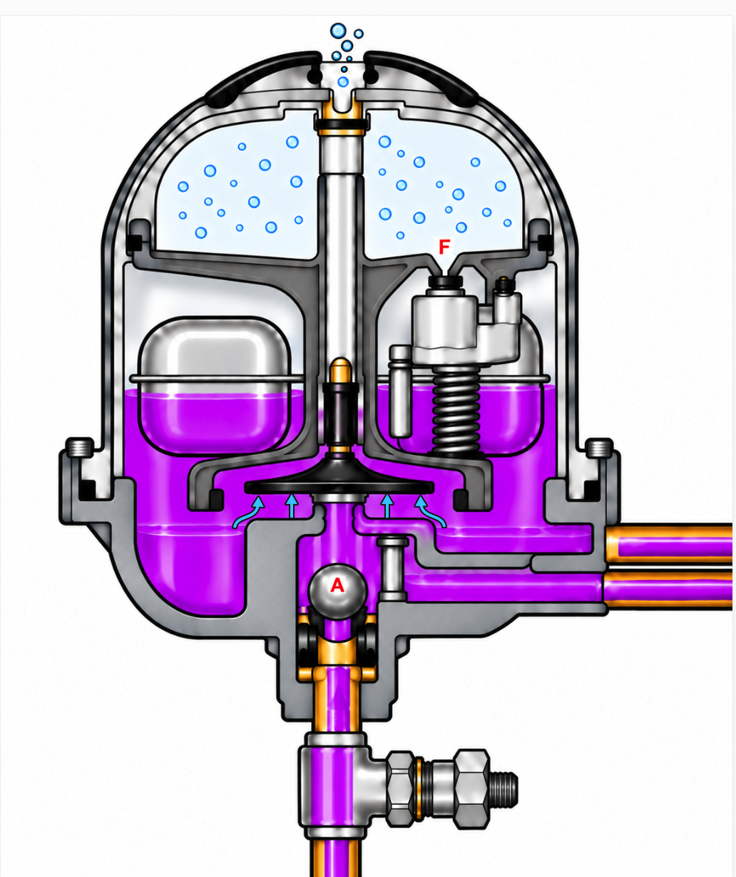
Check valve A drops to close off fuel from the tank until it is needed when pressure in the center chamber drops which closes valve seat D sealing off the center chamber from the lower chamber.
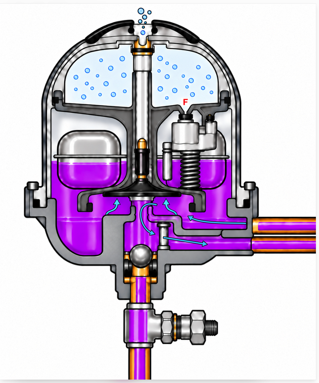
- If air enters the Tigerloop, the float drops, allowing the air to escape into the upper chamber.
- As the burner continues to operate, the oil pressure in the center chamber gradually drops as fuel is consumed. When the pressure drops, valve D closes, and ball check A opens, allowing more fuel to enter from the tank.
- As the center chamber refills and the oil pressure builds, valve D opens, allowing fuel to flow to the pump. At the same time, ball check A closes, stopping the flow of fuel from the tank.
- This cycle repeats continuously, with ball check A and valve D opening and closing in response to changes in oil pressure in the center chamber.
Hope that explains the TigerLoop operation clear as mud.
Ed
Edward Young Retired
After you make that expensive repair and you still have the same problem, What will you check next?
 3
-
I suppose it could be… but it was installed Fall of 2014. Perhaps it was manufactured earlier?
Yes, to the questions.
0 -
@EdTheHeaterMan said: Here is how the tiger loop works.
Good stuff Ed! Thanks!
0 -
Well cut me off at the knees and call me stumped. Can't wait to hear what the tech finds.
Keep in mind there was no suction leak caused by the original work. That's issue #1. Its possible there is a suction leak now from all the oil parts that were replaced. That's issue #2. A vacuum test will prove that.
PS, did you specify "knowledgeable oil tech"?
 1
-
🤣🤣🤣 Me too!
You mentioned the pre / post 2013 difference in burner/pump settings. I found that interesting.
I looked at my boiler manual, it is the 7/2010 revision. Online I found the 2014 version and of course it says what you said, that the later models use increased pump pressure.
Any idea why they made that change?
I find it a little odd that even at 180 PSI they are still using the same nozzle, and claiming the same 0.60 Firing rate. It's closer to 0.7 GPH @ 180 PSI

I did note that the Shutter setting has gone from 6 to 8 recommended starting point which makes perfect sense.
Do you think the updated pressure setting is 'backward compatible'? Anything bad happen if we go to 180 ? Anything good happen if we do?
0 -
As far as pump pressure, 180 is fine as long as it doesn't exceed the input of the boiler. Idk why all settings are the same. Beckett probably doesn't know either.
1 -
No Beckett probably doesn't know. That why i don't trust MFGS. I have run into this time and again. Setting are a good starting point but that is all they are a starting point. You have to combustion test and use your eyes, ears and nose.
 2
-
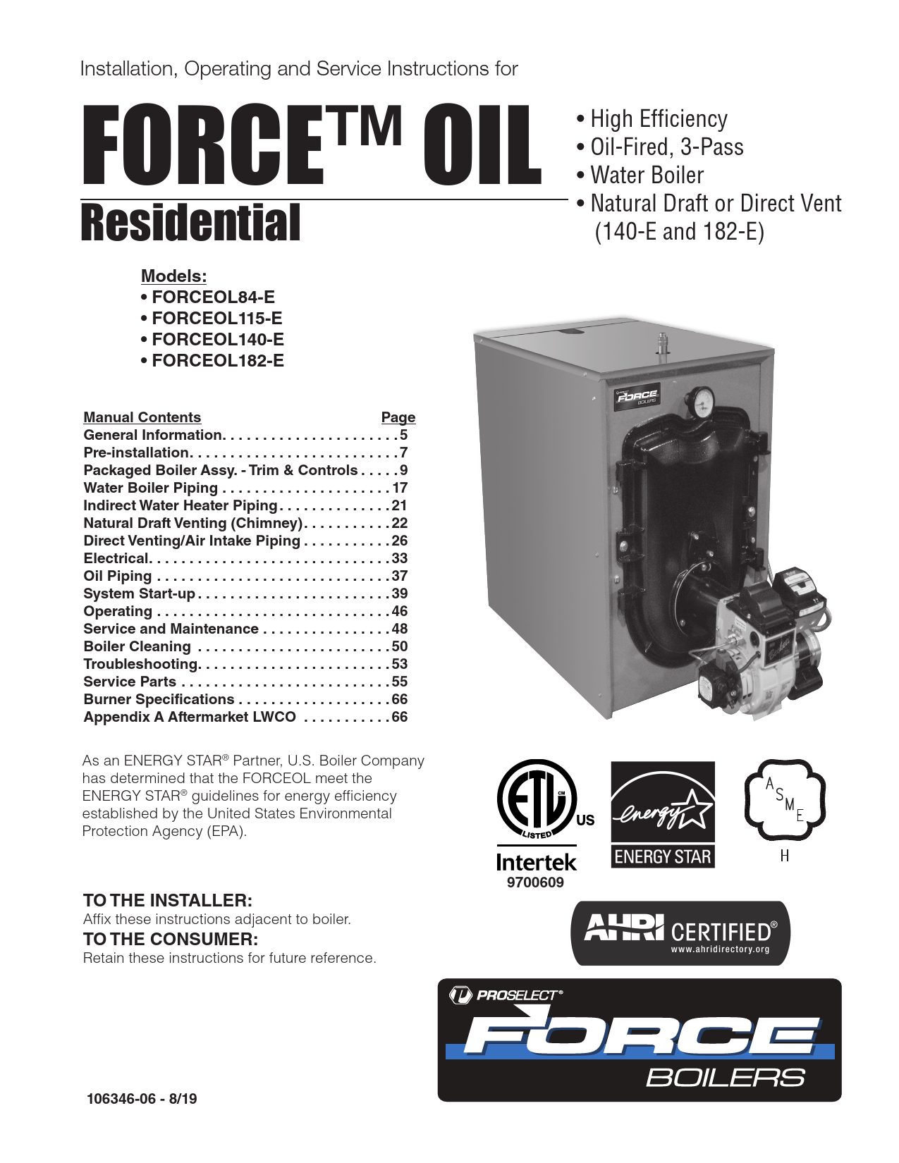
After pouring over the parts lists, it appears to me that the 84 is identical to the 115 in all respects EXCEPT…
The nozzle size and the placement of the baffles in the flue passes.
Every single other part is identical.
The 84 uses only baffles in the 3rd pass, and the 115 uses them in both the 2nd and 3rd.
I know this is an oil forum, but this coming spring I intend to switch over to gas.
If I can do a conversion burner and save the big bucks that a new boiler would cost me, I would love to do that. So I've been looking at the Beckett CG4 gas conversion burner. It's NOT spec'd out for the 84, but it IS spec'd for the 115. I suspect the reason is flue gas condensation. The 84's firing rate is likely not enough heat to prevent that. The spec's for the 115 state that both baffles are to be removed when the CG4 is installed.
Since the boilers appear to be the same block, is there any reason this boiler could not be fitted with the CG4 and simply remove the baffles and pretend it's a 115 and fire it per the specs for the 115? I know the firing rate would be higher of course, but the money I would save on replacing the perfectly good boiler would probably pay for the gas for years to come, probably past my existence.
Should I move this discussion to a different forum? Or is it OK to discuss it here?
0 -
The Beckett Gas Burner must match the boiler in order to get the needed air tube assembly because the flange is welded to the air tube. That said, if you can be 100% sure that the 115 air tube will fit your 84 then the next step is to get in touch with Beckett Tech Support and get it in writing. Call 1-800-645-2876 and talk to tech support and see if they agree with you on the details. I called them about a boiler that was not on their list and they said the burner is not compatible with the boiler. I recommended the Carlin Gas Gun to the customer.
Edward Young Retired
After you make that expensive repair and you still have the same problem, What will you check next?
1 -
@EdTheHeaterMan "Call 1-800-645-2876 and talk to tech support"
I bet they won't talk to a non-pro.
Anybody know if Ron Beck is still with them? I know Ron from way back…
0 -
I have a rebadged version of the same boiler that I installed 5 years ago. I could not get the boiler to run well with the older settings that the boiler came with. I upped the pressure to 180psi according to the updated specs and it runs beautifully now. I clean and service it every 2 years and there is minimal soot inside.
I've been following this thread out a curiosity and hopefully you get sorted out soon and post the conclusion.
0 -
What is yours badged as? I didn't know they did that.
I am considering going to 180PSI and was going to ask the tech about that, but forgot.
Past years cleaning mine I would say the 'minimal soot' is an understatement!
0 -
Do you have a video feature on your cell phone? A video of what you are describing would be most helpful. You can upload videos YouTube and post the link to that video. Posting videos to YouTube is easy. You can google how to do it. If I can figure it out without my grandson's help, then anyone can do it.
Edward Young Retired
After you make that expensive repair and you still have the same problem, What will you check next?
0 -
Another difference between the 115 and the 84 is the static plate on the nozzle assembly is different. Don't know if it's going to make that much of a difference, but Beckett calls it out.
 1
-
Hi Ed, I do, and I could… but at this point I'm pre-occupied with now having to find someone that can repair this!
Maybe later after I calm down a bit…
0 -
Yeah, I see that now… but if the boiler is able to be converted to gas, I guess that won't matter?
I may just go ahead and not buy that new car this year and instead go with a whole new boiler!
.
0 -
To Paraphrase my tag line:
After you fix that problem with a new gas boiler, and you still have a problem heating your home, what will you be driving? LOL🤣
Edward Young Retired
After you make that expensive repair and you still have the same problem, What will you check next?
 2
-
If you don't mind, explain your process for priming the pump.
0 -
@EdTheHeaterMan suggested:
- Is there a valve at the tank? If not them maybe you should put one there.
- Place a plug or cap at the end of the suction line in the tank. You can do this with a temporary fitting. You can remove the suction line from the bottom of the tank for this test.
- Then attach a vacuum gauge on the line at some location between the tank end of the suction line and the fuel pump.
- Operate the pump in order to get the vacuum up to 10" vacuum.
- The fuel line will hold the vacuum if there are no air leaks.
After the tech left I installed a high quality stainless steel ball valve at the upper loop coming out of the fuel tank. Yes, I used flare fittings.
I ran the burner up to close to 10" (high limit satisfied before I got all the way to 10", I figure 9"+ should be fine)
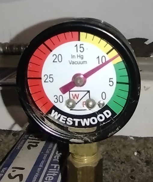
I'll check it from time to time… and wait until tomorrow if necessary.
0 -
Exactly. It's more like the old MPOs before the IQ control system came out. Either way the burner specs are the same. As a DIYer I like the fact the control system is very simple and easy to swap out.
1 -
I think it was mentioned earlier by one of the pros but have you ever tried running it right out of a portable fuel tank with a short length of line? Ever thought about bypassing the tiger loop and going to a typical single line setup? As a DIYer I like to keep things simple and not have too many bells and whitsles that can create more failure points.
1 -
Four hours later and the vacuum has dropped just a wee little bit, less than 1" of Hg. In the previous pic, the needle is just about a needle width above the green (8"). It actually did this drop within the first hour though, and has held steady since then.
I'll check it again in the morning, and update. If it's still just about 8", can I say perhaps that the initial pressure change was from the oil cooling off a little bit? Should it have stayed stone cold solid?
0 -
If you are holding a vacuum for more than 15 minutes than there is no significant vacuum or air leak in that system. in this illustration, all the fittings parts and piping in the green area are not leaking. If there is a leak between the TL and the Fuel Pump, then the check valve in the TL inlet can close that off and isolate that section from the vacuum gauge on the Spin on filter.
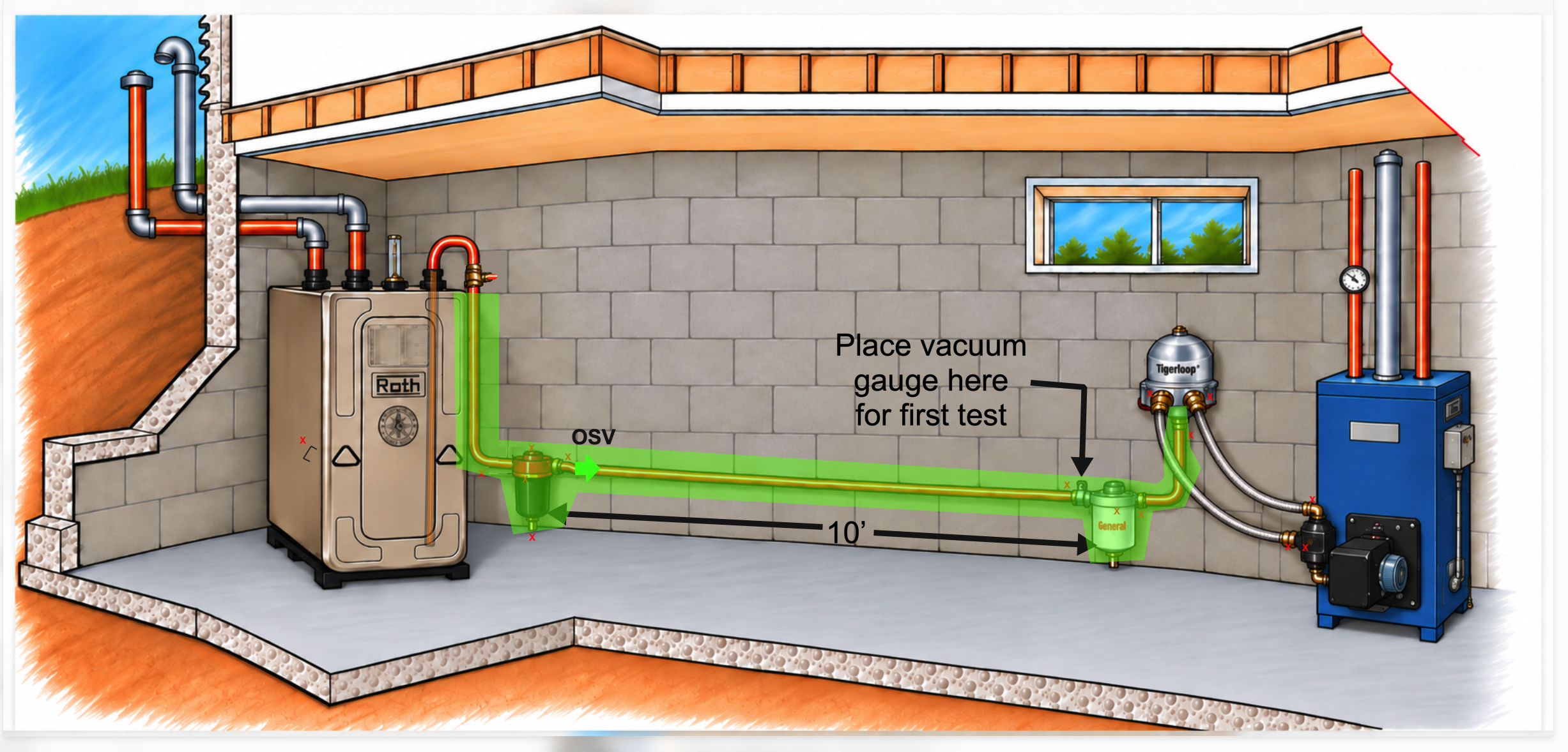
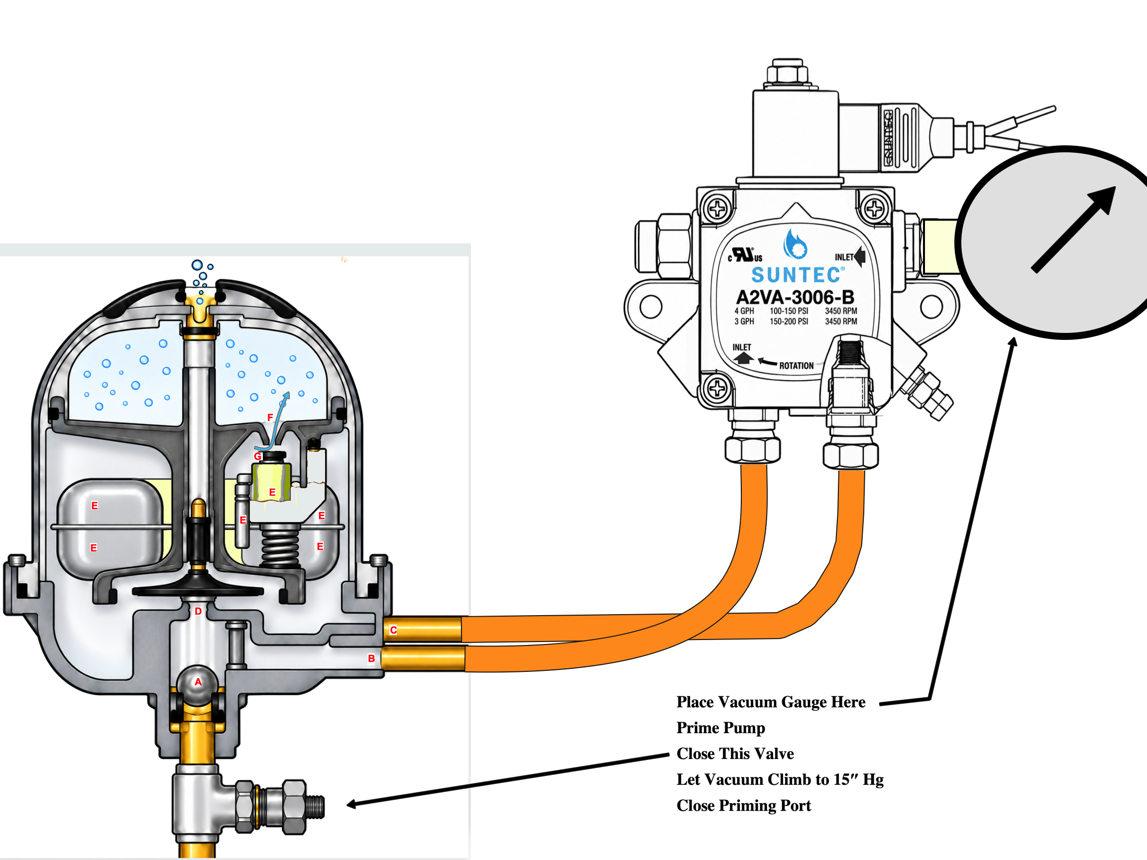
Your next test is to place the vacuum gauge in the fuel pump extra port.
Edward Young Retired
After you make that expensive repair and you still have the same problem, What will you check next?
0 -
No, not yet, but the 'day tank' will be next, after the vacuum test overnight.
I thought about going single line, but with that small nozzle I'm a skeert that cold oil would become a problem. There is no heat in the part of the building where the tank is. That's the reason we went with the TL in the beginning, to get a bit of heat into the oil before it hit the nozzle. Maybe it's not necessary, but I prefer higher confidence.
0 -
I've got a big (at least a gallon, maybe a little more) clear plastic pretzel jug and a tight fitting piece of clear tubing from my vacuum brake bleeder kit.
Call for heat, press the button on the primary to extend the bleed cycle to 45 seconds, open the bleeder.
Oil / foam comes out.
Close bleeder, burner fires.
I've done this MANY times in the past few days. Still, every time the unit sits idle for a period of time, I get the air and foam… sometimes not so much, sometimes a LOT. Even if I bleed a full container, there are still some tiny bubbles showing in the clear tube.
1 -
@EdTheHeaterMan "Your next test is to place the vacuum gauge in the fuel pump extra port."
Ahhh, OK… by 'extra port', I presume that you mean the unused inlet port?
I'll have to cobble some fittings together to make that happen…
I'll need to adapt the 1/4" port to 1/8" for the gauge. I can do that.
I presume that the procedure would be the same? Run it up to say 10" Hg and shut it down and wait?
"holding a vacuum for more than 15 minutes"
By "holding", you mean that inch or so that it dropped so far in the past several hours is not a concern? And that if that does indicate a TINY air leak, the TL should be able to handle that?
0 -
Edward Young Retired
After you make that expensive repair and you still have the same problem, What will you check next?
0 -
By "holding", you mean that inch or so that it dropped so far in the past several hours is not a concern? And that if that does indicate a TINY air leak, the TL should be able to handle that?
If you hold a vacuum for 15 minutes and it does not drop from 10" to 9.5" in that 15 minutes, that that is a good sealed system. if there was an actual leak, it would drop to 5" or less in 15 minutes. and the TL would be able to handle that size leak with no problem. I would try to find and fix a leak of that size but if you don't have enough time and must move on the the next no heat call, I would let the TL do its job and make a note to look for that leak at a later time when there is more time for such repairs.
That is from the viewpoint of a service tech on a cold winter day that is obviously going to turn into overtime for him and his fellow technicians.
From your viewpoint, you have the time to do the testing now and a 1/2" of vacuum over 4 hours is considered a system with no leaks IMO.
Edward Young Retired
After you make that expensive repair and you still have the same problem, What will you check next?
 1
-
"a 1/2" of vacuum over 4 hours is considered a system with no leaks IMO"
OK, I'm probably good then as far as the lines go. It's dropped about an inch in 6 hours.
Just want to clarify this part, I won't be able to get to this until Friday unfortunately… but want to make sure I've got it correct.
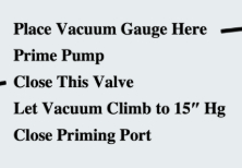
I prime the pump, but leave the primer port OPEN while I close the Firomatic at the inlet to the TL ?
The vacuum will climb to 15" with the Priming Port OPEN?
And then close the Priming Port? (I presume the burner will fire then? But of course I should shut it down at that point.
How does the fuel cutoff solenoid affect this, if at all?
0 -
Install a permanent vacuum gauge.
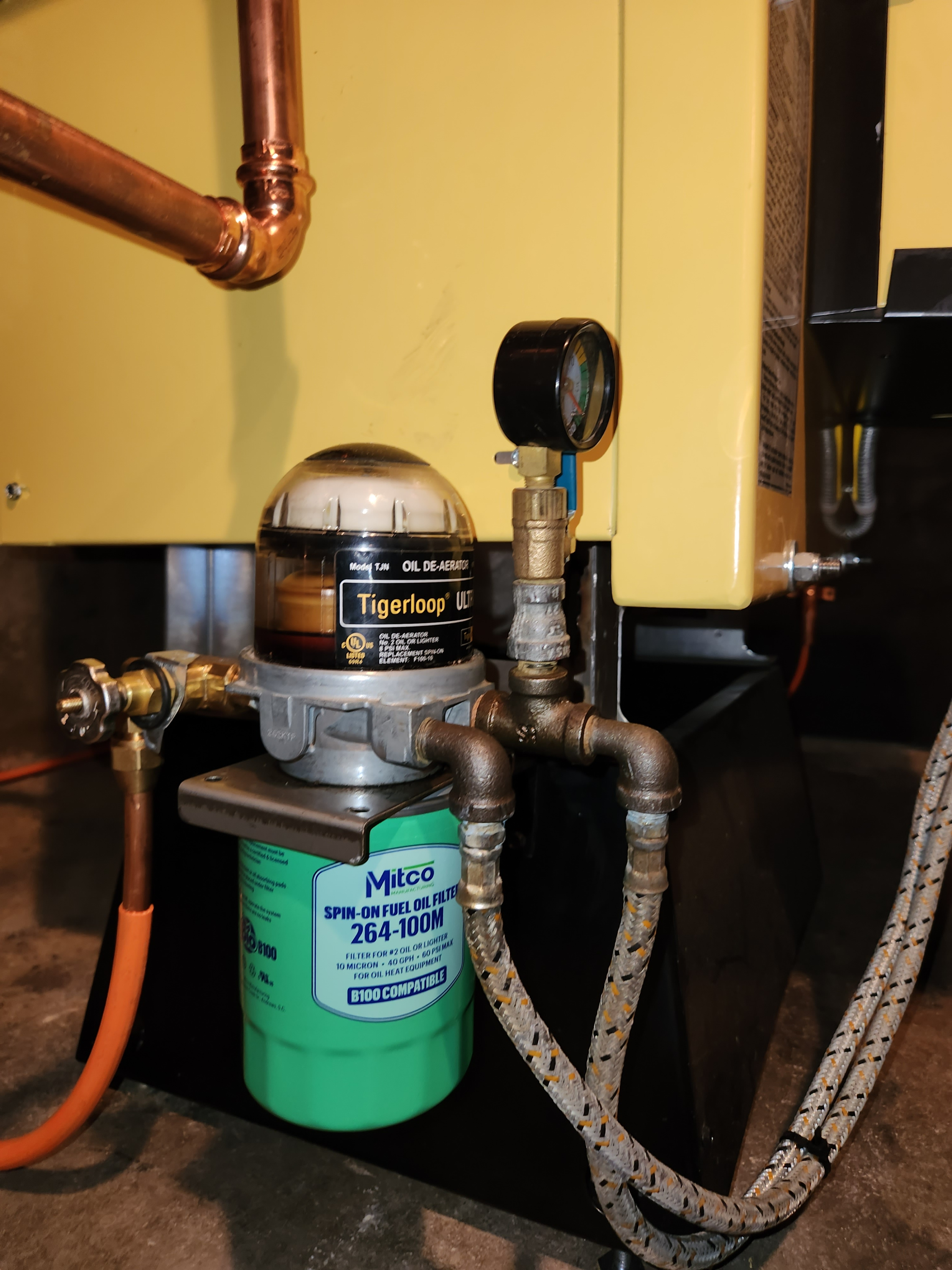
I know, stupid question, but I'm running out of logical reasons. The arrow "out" of the TL is going to the inlet on the fuel pump, and the return line from the fuel pump goes to the arrow "in" on the TL?
If we ever meet in person you can punch me for asking.
1 -
Yes. the arrows are the direction of oil flow. Maybe it would be better if they put those arrows inside the pipes and fittings so the oil will know which way to go.
And Yes, you git the Vacuum test procedure correct.
Edward Young Retired
After you make that expensive repair and you still have the same problem, What will you check next?
1



Categories
- All Categories
- 87.9K THE MAIN WALL
- 3.3K A-C, Heat Pumps & Refrigeration
- 60 Biomass
- 430 Carbon Monoxide Awareness
- 134 Chimneys & Flues
- 2.2K Domestic Hot Water
- 6K Gas Heating
- 124 Geothermal
- 170 Indoor-Air Quality
- 3.9K Oil Heating
- 80 Pipe Deterioration
- 1.1K Plumbing
- 6.7K Radiant Heating
- 397 Solar
- 16.1K Strictly Steam
- 3.5K Thermostats and Controls
- 56 Water Quality
- 51 Industry Classes
- 52 Job Opportunities
- 18 Recall Announcements