The math isn't mathing!

Ok, I'm a civilian homeowner, not a specialist. I've learned a lot reading on here.
Here's the situation. I live in suburban Philadelphia. I purchased my house in 2019. It is a mid-20th century 1.5 story cape. The windows have been updated to double glazed, argon filled vinyl windows. The exterior walls are 4 inch with batt insulation. Full basement, uninsulated, block foundation.
Hot water baseboard heat. When I purchased the house, it used Fuel Oil as the fuel. Boiler is dated about 2015. In 2021, made the decision to convert to Natural Gas. Talked to several contractors. The one I went with (a) came highly recommended and (b) was the only one who arrived and asked this question: "How is it working now?"
The house has 3 heating zones. All of the 1st floor is one zone, about 1250 sq ft, about 60 linear ft of baseboards. It is balanced reasonably well, but has trouble when the outside temp drops below 10-15F. It can run continuously (pump running, boiler firing on 10 mins, off 10 mins), but not gain very fast.
There are two big upstairs rooms, with 3 ft high kneewalls, then up to a narrow strip of 8 ft ceiling. Each room has it's own thermostat and baseboard units. The upstairs rooms actually seem to work better on the cold days.
When they did the gas conversion, they replaced the oil burner with a gas burner. They also recommended installing a buffer tank to mainly help the smaller, upstairs zones. We did all that work. And, it is somewhat better—and the $ savings of the oil-gas conversion has paid for the modifications in the last 4 years.
Now, this last winter, when we had record cold for more than a few days, the problems on the first floor really became obvious. And, I've been looking at the calculators, and that is my title: the math just ain't mathin.
1250 sq ft. Assume 45 BTU/sq ft (seems to be a reasonable rule of thumb value)=56,250 BTU for the first floor. Divide by 600 BTU/Ft for the existing baseboard, we get 93.75 ft required.
The total 1st floor baseboard dimensions are about 60 linear ft.
Calculating the other way, with the existing baseboards, I have available about 30 BTU/sq ft. Observationally, I'm fine as long as the outside temp is never below 20F.
I say, no wonder it's cold and takes forever to warm up.
- Am I missing something?
- What are the options? (That won't cost thousands of dollars)?
Comments
-
What are the low and high limit and differential settings on your boiler's aquastat? Are they close to what you see on the boiler's water temperature gauge during heating cycles?
This may be a simple matter of increasing the supply water temperature in colder weather.A picture of the aquastat with the cover removed would help. We also need to know the make and model number. Also please take some photos of the boiler, circulator pump, zone valves and surrounding piping.
—
Bburd 1
1 -
Just curious—does your first floor have any areas underneath it that are exposed to the outside temp (like a garage or crawlspace)? Those areas would suck a lot of BTUs out of your first floor during very cold stretches.
NJ Steam Homeowner.
Free NJ and remote steam advice: https://heatinghelp.com/find-a-contractor/detail/new-jersey-steam-help/
See my sight glass boiler videos: https://bit.ly/3sZW1el0 -
The first floor is 100% over the basement. Because the house is built into a hill, roughly half the basement is at or near grade, with a walkout door.
Aquastat is set at 190F.
Contractor has suggested splitting the 1st floor into 2 zones, with a major bearing wall as the split point (the piping splits into 2 loops in the basement-the boiler is more or less in the middle) and also replacing the circulator with what he called a "lower speed" pump (less flow rate?) to give the hot water more time inside the baseboards to get more heat out into the rooms.
I have looked into what it would take to insulate the basement walls. I'm surprised at what basic batt insulation rolls cost!
0 -
Our 100-year-old 4-unit condo building near Boston has a first floor built entirely over an unheated, unfinished concrete wall/floor basement that hovers around 60 degrees in winter, and even with that, our heat loss is under 20 BTU/hr/sq ft. You are farther south, in a better insulated building, so I would suggest your 45 BTU/hr/sq ft guess is way high. You're probably closer to 20 BTU/hr/sq ft, which would put your first floor heat loss at 25,000 BTU/hr, needing about 50 feet of baseboard. So you may have enough radiation but insufficient flow and/or insufficient water temperature.
Has the first floor loop been purged to get all the air out? Air in the loop will interfere with flow rates.
Also, your contractor seems not to understand heat transfer. Lower flow rates do not increase heat transfer to radiators, they reduce heat transfer. So you either need higher flow rates (which can be accomplished by judicious repiping and/or more capable circulators, and sometimes just by purging air from a loop), or higher temperature water, or even both.
But the fact that your contractor thinks a lower flow rate will increase the heat output of a radiator is worrisome.
 1
1 -
The math is mathing OK; it's just not cooperating with the physics.
Fortunately you mention that your circulating pum runs all the time — but that the boiler doesn't. Good news! That means that you have additional capacity in the boiler, and finding a way to use that is a lot less expensive than some other options might be.
Basically you appear to be limited by the amount of baseboard you have. I regret to say that neither of the two ideas put forward by your contractor would do anything to help the problem, and your water temperature is about as high as it will go.
So… you need to add radiation (cutting heat loss from the basement will help, too, but that's another story). You probably have about as much baseboard as the rooms can take, but… worth looking at. Another option is wall mounted panel radiators;. Pretty flexible as to installation and not obtrusive. There may be other options.
Br. Jamie, osb
Building superintendent/caretaker, 7200 sq. ft. historic house museum with dependencies in New England0 -
Something else to check: is air free to flow through your baseboard radiators? High pile carpets can block the inlet slots, or furniture pushed up against them can block the flow in or out. You want about 1 inch free underneath, and the same above.
What size pipe is that first floor zone? It should be three-quarter inch or more all the way to avoid excessive temperature drop through the circuit.
—
Bburd0 -
@jesmed1 said "But the fact that your contractor thinks a lower flow rate will increase the heat output of a radiator is worrisome."
In some cases, it will.
I see this primarily in older gravity systems that now use forced circulation. These have much less resistance to the flowing water, so are easy to over-pump. The water will flow in a straight line between the inlet and outlet of the radiator, rather than diffusing thru the entire radiator as it should. Here's one I ran into many years ago:
And a guide for sizing circs in these systems:
Check your ΔT if you suspect this. If it's less than 10° F, you're probably over-pumped.
All Steamed Up, Inc.
Towson, MD, USA
Steam, Vapor & Hot-Water Heating Specialists
Oil & Gas Burner Service
Consulting0 -
i would start with doing a real manual j heat loss calculation using an online or app calculator. since your first floor has a second floor above it, it won't have loss through the ceiling which is where most loss typically occurs, you only have loss through the floor and the exterior walls.
I would check the temp of the baseboard in several locations with a clamp on thermometer.
is the area under the baseboard covers clear, is there at least an inch or 2 between the flooring and bottom of the covers? are the covers in place? are the fins reasonably clean? is the damper open fully on the covers?
0 -
To a few of the comments:
Yes, there is plenty of room above and below the baseboards. Laminate floors, no carpet.
He did exactly say that he thinks it's overpumping (he spent some time in the basement talking to himself as he walked around the pipe loop with a heat gun).
Also note that this is a mono-flo tee system.
His comment about splitting the 1st floor from a single zone with a "B" shaped loop to two single loop zones was that with the split like it is, it's likely that more water is flowing one way than the other—making one side warmer (true) than the other side, and splitting it in two will help the balancing act.
0 -
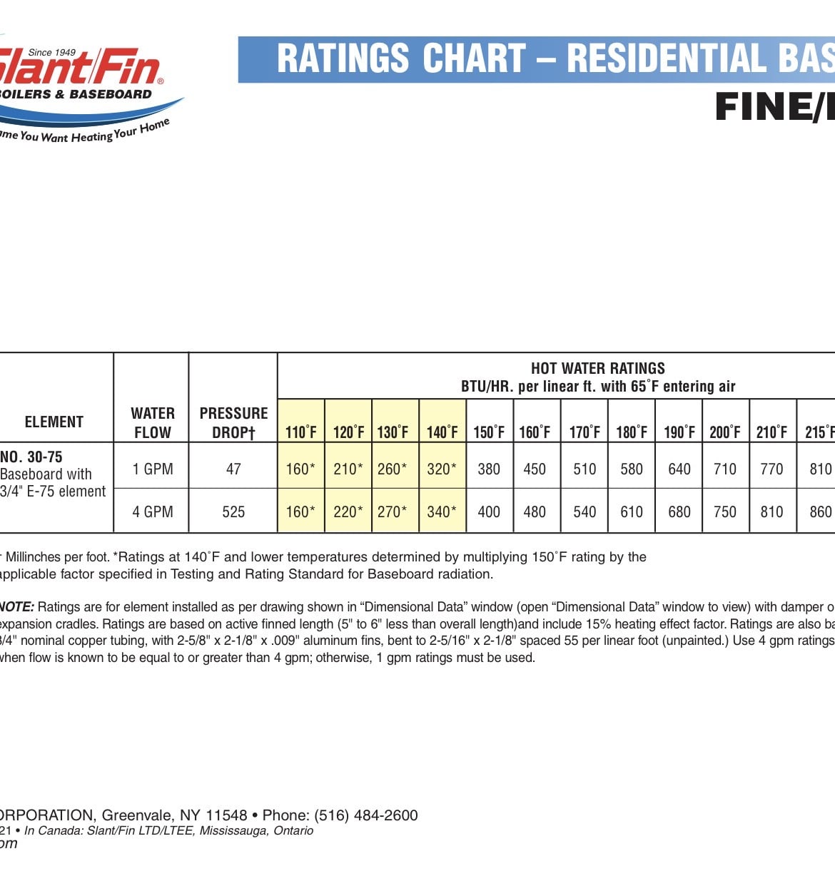
fin tube at AWT of 180 is probably closer to 550btu/ ft
So 60’ x 550= 33,000 btu/hr delivered
30,000/ 1250 is 26btu/ ft that seems low for that building, as you are experiencing
A heat load calc for the first floor would confirm you are under radiated
You can squeeze some additional output from fin tube by increasing the flow rate. 4 gpm is possible in 3/4 tube
Fin tube charts clearly shows increasing flow from 1 -4 gpm, which reduces delta which in turn increases average fin tube temperature, will increase btu// ft output
With SlantFin # 30 fin tube note the output increase from 580 to 610 with more flow. Sometimes this is possible by increasing soeed on a multi speed circulator.
This applied to any type of heat emitter
the 10 minute run time seems low also if you have a buffer tank?
Bob "hot rod" Rohr
trainer for Caleffi NA
Living the hydronic dream0 -
you can solve the balance with more circulator or a balancing valve or a less restrictive zone valve. monoflo is tricky, if you don't have enough flow you will get flow in the main but not through the emitter since the main is the easier path.
how are the 3 zones set up, are they all monoflo? how is the zoning done, are there 3 monoflow loops or what?
were the zones separated from one zone at some point? you have to remove monoflo tees or adda bypass between the branch of the tees if you remove emitters from a monoflo system.
0 -
I know the 1st floor is all monoflo. I don't think the 2nd floor is.
One zone is the whole first floor, the boiler outflow goes to a tee that splits it between the "front" and "back" of the first floor, and they rejoin just ahead of the zone valve. His proposal is to route the two loops on the first floor to two zone valves, so the 'front' and 'back' of the first floor are controlled separately. The 'back' DOES warm up faster and stay warmer than the 'front'.
The other 2 zones are two rooms on the 2nd floor. I know there is a single pipe going 'up' to the 2nd floor, and a tee up there in a closet that splits the flow to the two rooms. Each room has it's own return 'down' to a zone valve, each room has it's own thermostat. Each room upstairs has a single baseboard unit.
0 -
Thanks. From the OP's description of the house as mid-century, I assumed it would have fin-tube radiators, in which case lowering the flow rate is not going to increase heat output. Maybe the real problem here is balancing as others have suggested.
0 -
the 007 that is packaged with boilers is frequently too small to get enough flow for a monoflo system and the zone valve adds a lot of restriction to the zone. you have to do the math on the circulator in this case and possibly find a less restrictive zone valve or change it to 2 valves separately on the returns. getting the air out of monoflo systems also can be difficult. are all of the emitters getting hot like close to the temp of the supply main and all the way across?
incidentally, decreasing the flow in the monoflo loop is likely to make it not heat at all.
0 -
Is this a new issue? did you have have this issue with the oil burner?
Since you now have said it's a monoflo you should check that all the emitters are free of air.
Check your delta T. You want that loop hot at the end.
0 -
I note that one proposal was to cut out all the monoflo tees and 'straight pipe' the whole setup into single loops. Honestly, the cost for that project made it prohibitive. A lot of $$ for unknown gains.
0 -
Nothing wrong with a monoflo if its been set up correctly from the original installation. It's the modifications from remodels that change how well it operates. Changing of a circulator that doesn't match the original pump curve.
0 -
This is a classic example of a situation where the amount of heat the boiler produces is greater than the amount of heat the emitters can radiate. The fact that your burner operates for 10 minutes on and 10 minutes off at or below design temperature is a clear indication of that condition.
Let's assume there are about 40 additional feet of baseboard on the second floor, for a total of 100 feet of baseboard. If we also assume that the supply temperature at the beginning of the radiators is 180°F (the high-limit setting) and the return pipe temperature is 160°F (a 20°F difference), the average water temperature in the baseboard loop(s) is 170°F.
If we use the Slant/Fin chart for the heating output of the baseboard, that would put the output of the heat emitters at about 525 BTU per hour per foot. At 100 feet of baseboard, the system can dissipate 52,500 BTU per hour.
Now, if the burner has an input rating of 140,000 BTU per hour, with combustion and thermal efficiency that results in a net output of about 105,000 BTU per hour, it makes sense that the burner can only operate for about half of each hour. In other words, it would run approximately 30 minutes out of every hour, or 10 minutes out of every 20 minutes.
So your math is adding up perfectly.
Part Two
You don’t need all that heat until the outdoor temperature approaches the design temperature of the system. That means you won’t know if your calculations are correct until the weather gets cold. So how do you determine whether major repiping is necessary?
The first step is to look at the problem zone—the first floor—with 60 feet of baseboard.
Measure the inlet temperature of the baseboard loop (the supply pipe at the boiler) and the outlet temperature of the loop (the return pipe at the boiler) when only that zone is calling for heat. Allow the burner to run until it shuts off on the limit control. Then observe the temperature difference between the supply and return.
You are looking for a temperature drop of no more than about 20°F. If the temperature drop is greater than 20°F, then splitting that 60-foot zone into two 30-foot loops with a common return (or supply) pipe may help improve heat distribution. If the temperature drop is 20°F or less, then the additional piping will probably not improve the situation.
Another test is to observe the room temperatures when the problem is occurring. Are the rooms closer to the supply side of the loop warmer than the rooms closer to the return side? A difference of about one degree is not a problem, but a difference of several degrees suggests an imbalance that repiping could help correct.
A rule of thumb I used to follow is that 75 feet of fin-tube baseboard element is about the practical maximum for a ¾-inch copper loop. Since you only have 60 feet, you will probably not benefit much from repiping the zone.
Part 3
The easy solution is to increase the boiler high limit temperature 10 more degrees above the 180° to 190°. Just looking at the SlantFin chart above that will increase the BTUh output of the boiler and radiator system from 525ish BTUh to 660ish BTUh per foot. That will add an additional 135 BTUh per foot of an additional output. That is all you may need to do and that does not cost you a dime if you make the adjustment yourself.
Part 4
Don't leave the high limit at 190° all year. Set it lower during milder weather because it costs more to heat the boiler water to that temperature.
If this test proves that you do not need additional piping or other work, and you would like an automatic way to set the high limit control to a lower temperature for most of the year—and only use the higher limit when it is very cold—then ask me for that wiring diagram and I will show you a few different options.
Edward Young Retired
After you make that expensive repair and you still have the same problem, What will you check next?
 1
1 -
I agree Ed. But i would like to know if he had this problem with the oil fired boiler.
0 -
or adding a zone valve that doubles the resistance of the loop from the original one zone system.
0 -
If anything, before the oil to gas conversion—which included adding a buffer tank—it was worse. The stated purpose for the buffer tank was to deal with the situation where one or both of upstairs 'small' loops was running solo.
The buffer tank addition included a new circulator: the original, boiler mounted circulator feeds the buffer tank, and the new circulator runs the house loops.
As near as I can tell, there is no air in the emitters. The buffer tank includes an air removal valve on top. I did open a couple of the bleed valves on the emitters at different times, and never got any air. They do get plenty warm.
The temp is supposed to go way down tonight, so it will definitely be running tomorrow, and I'll see what I can do to get some temperature readings.
0 -
Philadelphia Low Temp is only 42° forcast for tonight. are you north and west of the city? if gets colder there. But you will not be near design temperature so you will not get to test the higher temperature limit, so keave the limit where it is for now.
Edward Young Retired
After you make that expensive repair and you still have the same problem, What will you check next?
0 -
I'm in central Bucks
0 -
I had 90' of baseboard in my ranch about 1100 sq feet and it needed every bit of it. The attic was pretty well insulated but the windows were lacking.
You need more radiation but you already know that.
Get the radiation up to around 100 feet and you will be fine.
Don't forget in the 50s and 60s Taco and the other MFGs pushed for 200-220 degree water all the time. Read the old books and you will see that.
This was done to decrease pipe size and radiation length to keep the install cost down to compete with warm air. Fuel cost wasn't an issue back then Install cost was.
People keep thinking that 200 or 220 water will boil or the boiler will "blow up"
It won't
Now for increased efficiency we go for lower water temps.
There is nothing magic about the standard 180 deg water any more than there is about a 20 degree TD
0 -
if i were going to add to the radiation i would probably add a couple panel radiators in strategic spots on a separate zone controlled with the downstairs zone. hopefully yo have enough pump for that.
since it is monoflo there is no easy way to add radiation without screwing up the monoflo
but i'm going to say this again since it seems to be getting ignored in favor of guesses that are plausible:
do a manual j so you know what/if you need to add.
0 -
I lived with an old monoflow system for 34 years. I liked it and it worked well
But
They are a PITA to get the air out of it. Make sure your radiation is not air bound before laying out the $$$$$
 1
1 -
I didn't realise you have a Monoflo® tee system on the first floor of your original home. When replacing the boiler with one that comes with a Taco 007 circulator and adding additional zones to the second floor and then again to the porch over the life of the system, you can't be sure that the pump that comes with the boiler can do all that work. My original comments about the 75 feet of baseboard maximum on a 3/4" loop do NOT apply to a Monoflo® system. What size is the pipe for the first floor zone? For that size system it could be 3/4" with 3/4 x 1/2 monoflo tees to the section of radiator that is no longer than 25 feet of element each. Most systems like that were about 12 to 15 feet each off of the main pipe.
If you have a 1” main pipe with 1” x ¾” Monoflo® tees then that is a different story. More info needed for the calculations.
Edward Young Retired
After you make that expensive repair and you still have the same problem, What will you check next?
0 -
I’m trying to understand your drawing. You mentioned that the house is a 1½-story Cape, and that two of the zones serve the second-floor rooms, each with its own thermostat. However, the sketch appears to show a single-story layout, with 3 of the zones located on the first floor. and the 4 zone for the water heater
Could you clarify how the second-floor zones are arranged, or update the drawing to show the second floor as well?
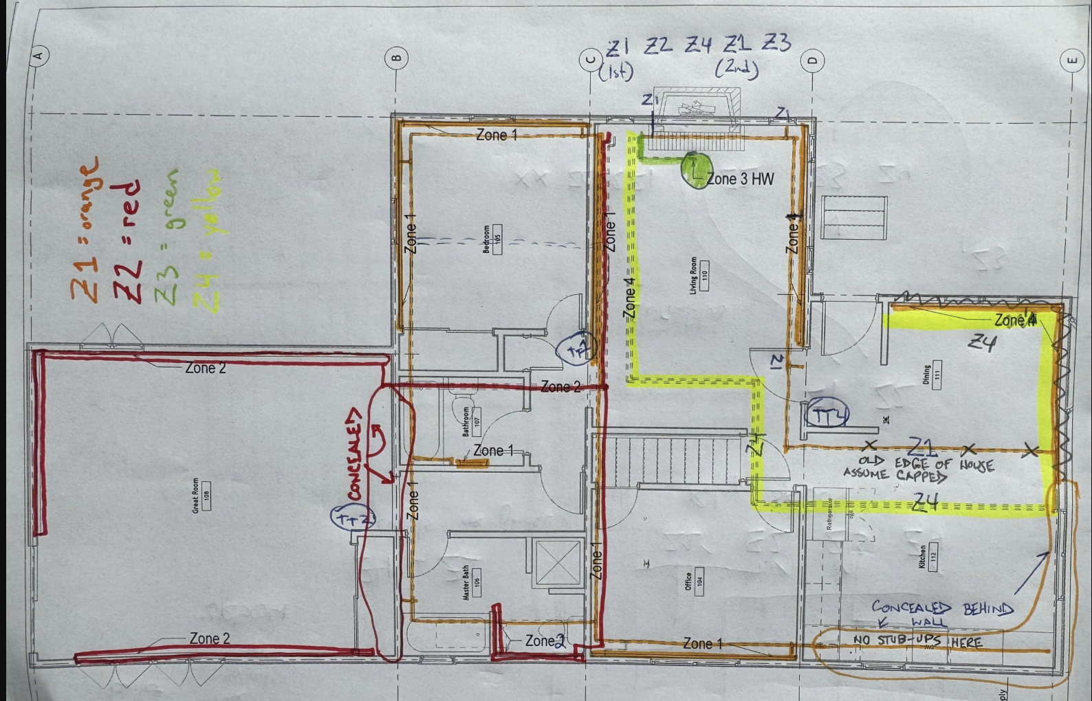
I have come up with this but do not know where the second floor radiators are
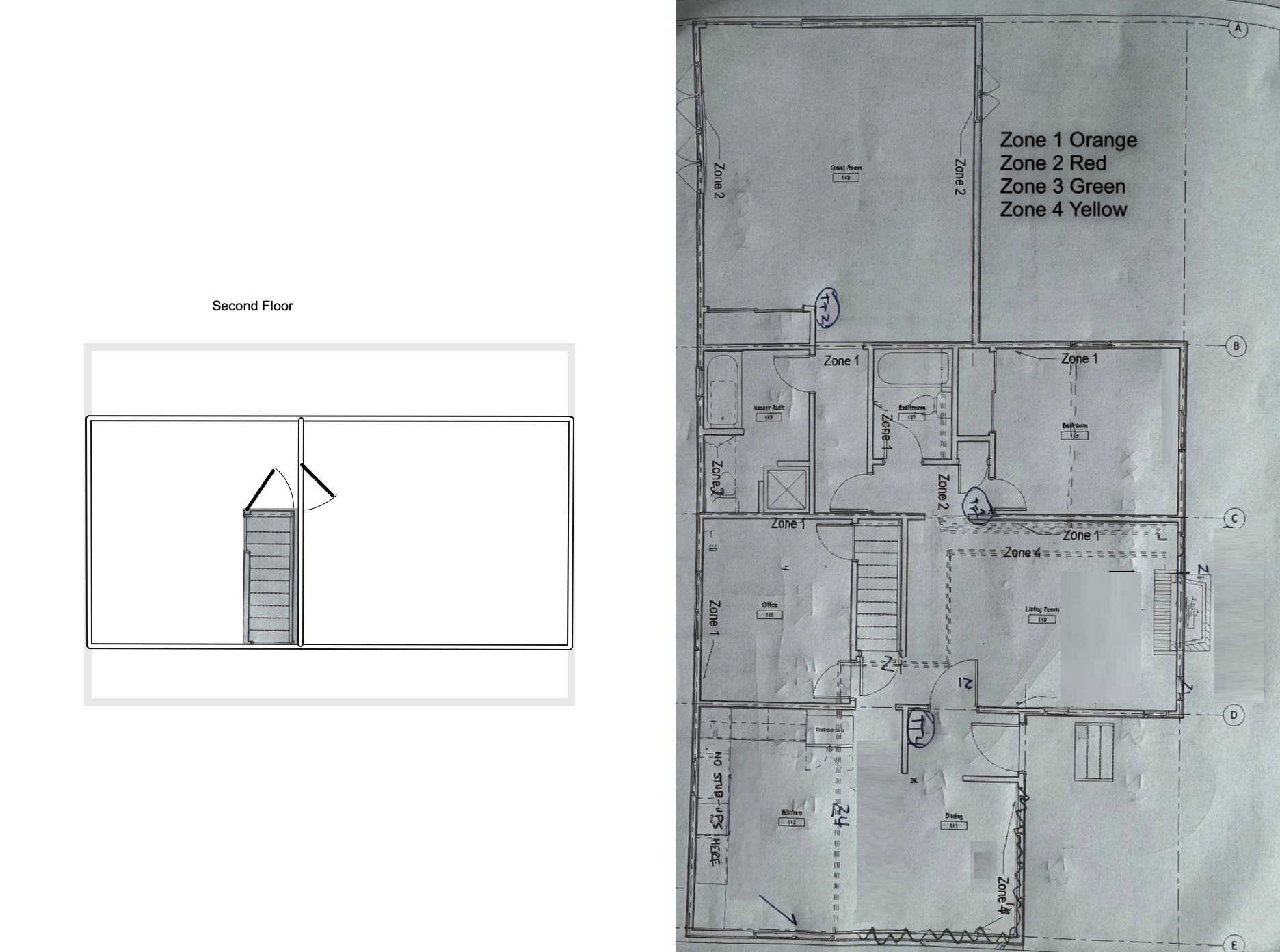
When showing the radiator locations it would be helpful to show only the radiator locations and not the pipes below the floor. Also what room the thermostat on the first floor zone is located.
Edward Young Retired
After you make that expensive repair and you still have the same problem, What will you check next?
0 -
Most Monoflow systems of that age were at least 1" main and more than likely it is 1 1/4"
0 -
This is what a typical MonoFlo® system using baseboard radiators might look like in your home.
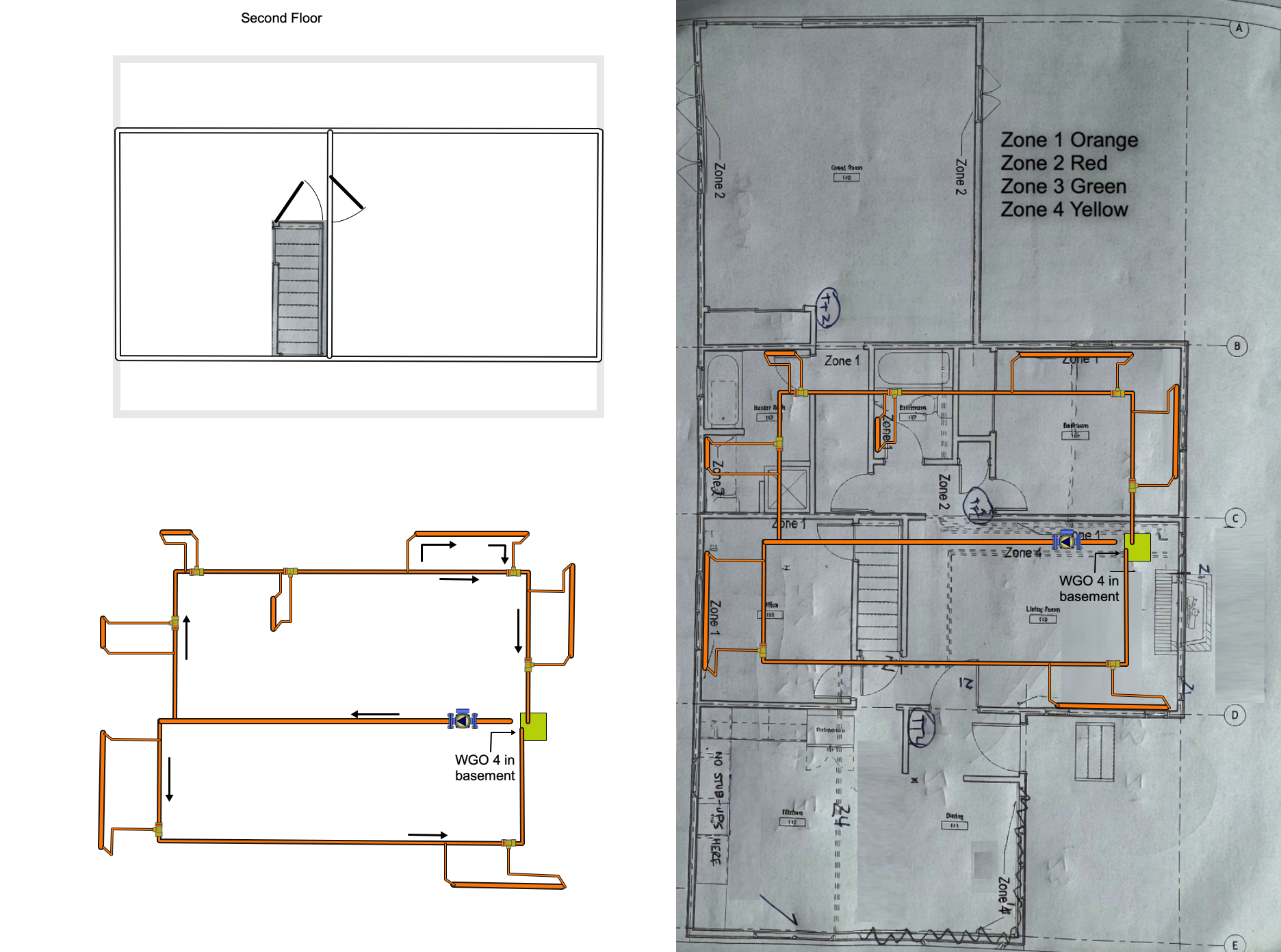
This is the Orange zone 1 in your home. It appears that your original 900 sq ft cape cod has had more than one addition over the life of the home. The new kitchen was added to what is normally the front of the house. The office appears to be where the original small dining room was. And the master bath was once the kitchen. The Great Room which I assume is the Master Bedroom looks like it could have been a two car garage on the back of the house at one time. With all these changes, there is a very significant possibility that your Monoflo® system is no longer in harmony with the other zones in the home.
Lets just assume that the original Zone 1 Monoflo® system is still balanced. I might be inclined to place that zone on its own circulator. That would eliminate any problem with the other zones using all the pump’s flow and head at the expense of the more restrictive Monoflo® system zone. That may be the only real solution to your problem of balance, if getting all the air out of the system does not get you where you need to be.
Remember this important fact: if you try to get air out of the system and no air comes out, then you don't have an air problem.
Edward Young Retired
After you make that expensive repair and you still have the same problem, What will you check next?
0 -
Remember this important fact: if you try to get air out of the system and no air comes out, then you don't have an air problem.
Or you don't have a proper purge set-up and or method.
Or proper purging technique
Mono-flo are tough to purge, more-so if they have been improperly modified.
Bob "hot rod" Rohr
trainer for Caleffi NA
Living the hydronic dream0 -
OK, OP here again
While I'm learning about hydronics, I DO know a little about fluid mechanics. I DO know how to use a pump curve.
That being said, without either a flow meter or multiple pressure gauges, how do you know how much flow is actually (a) leaving the circulator and (b) actually getting to—and through—the emitters (especially when dealing with a monoflo system)?
The main circuit pipe is 3/4 on each side of a tee that comes from the boiler. The line up to the tee appears to be 1-1/4. The tees are 3/4 X 1/2. Each emitter has an installed bleed valve on the outlet end.
The new buffer tank also has an automatic bleed valve on top of it.
All of the emitters DO get hot, and there are no gurgling/popping noises that could indicate air.
I did note one comment about water temperature(!). That 1980 and earlier vintage systems were designed to operate hotter than modern systems. I also know how to read a steam table, and understand that a pressurized system creates a higher boiling point.
So, here's the question: never mind efficiency questions—how hot can you safely go?
0 -
measuring temps gives you a decent way to guess combined with doing the math for the resistance of the piping.
if you have enough flow the delta between the supply and return end of the emitter should be relatively small.
i would strongly encourage you to do the heat loss calculations to know what you are shooting for.
0 -
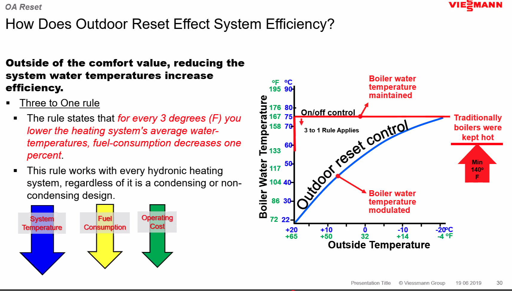
You can safely run 190- 200° if you need to. With and outdoor reset control it would run those high temperatures only on design days, hopefully.
But with increased operating temperature boiler efficiency drops. Another reason to consider ODR.
 Bob "hot rod" Rohr
trainer for Caleffi NA
Living the hydronic dream0


Categories
- All Categories
- 87.5K THE MAIN WALL
- 3.3K A-C, Heat Pumps & Refrigeration
- 59 Biomass
- 429 Carbon Monoxide Awareness
- 124 Chimneys & Flues
- 2.2K Domestic Hot Water
- 5.9K Gas Heating
- 118 Geothermal
- 168 Indoor-Air Quality
- 3.8K Oil Heating
- 78 Pipe Deterioration
- 1K Plumbing
- 6.6K Radiant Heating
- 394 Solar
- 15.9K Strictly Steam
- 3.5K Thermostats and Controls
- 56 Water Quality
- 50 Industry Classes
- 50 Job Opportunities
- 18 Recall Announcements