How do I hook it up?

OK, new motor is here, I will test cap before I hook anything up.
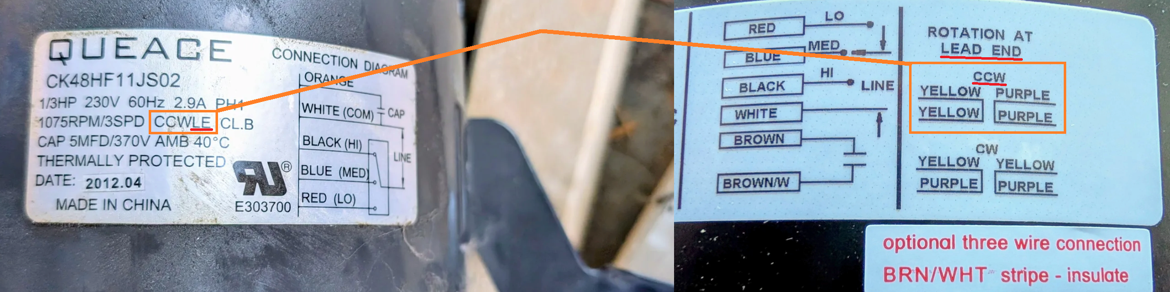
Here is the old wiring from old motor tag.
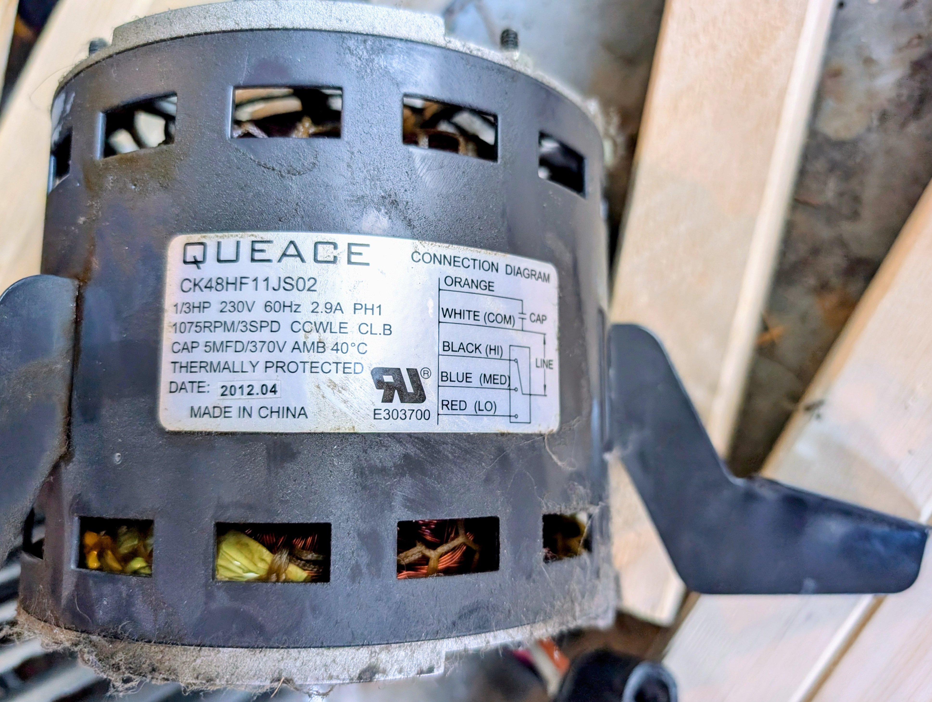
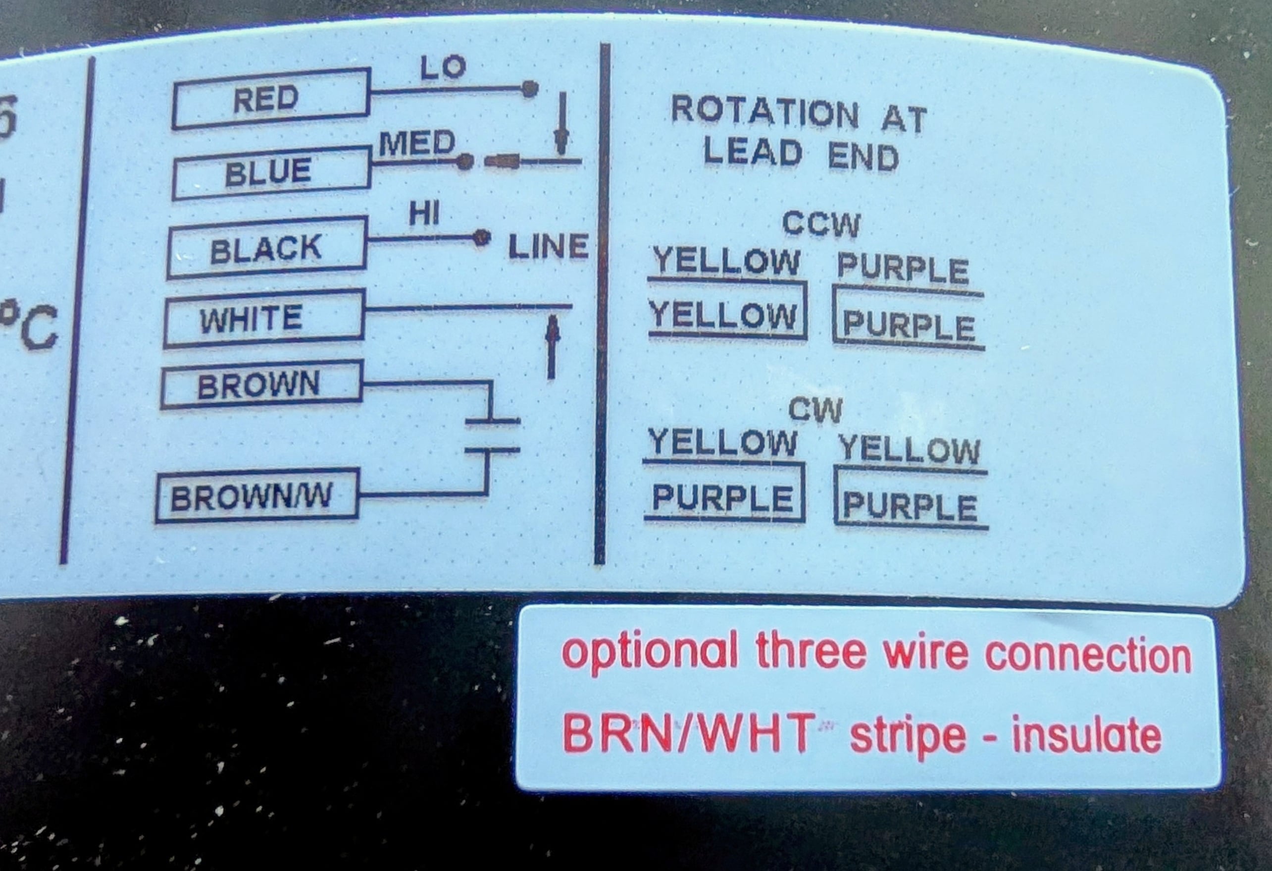
Here is new wiring on on new motor.
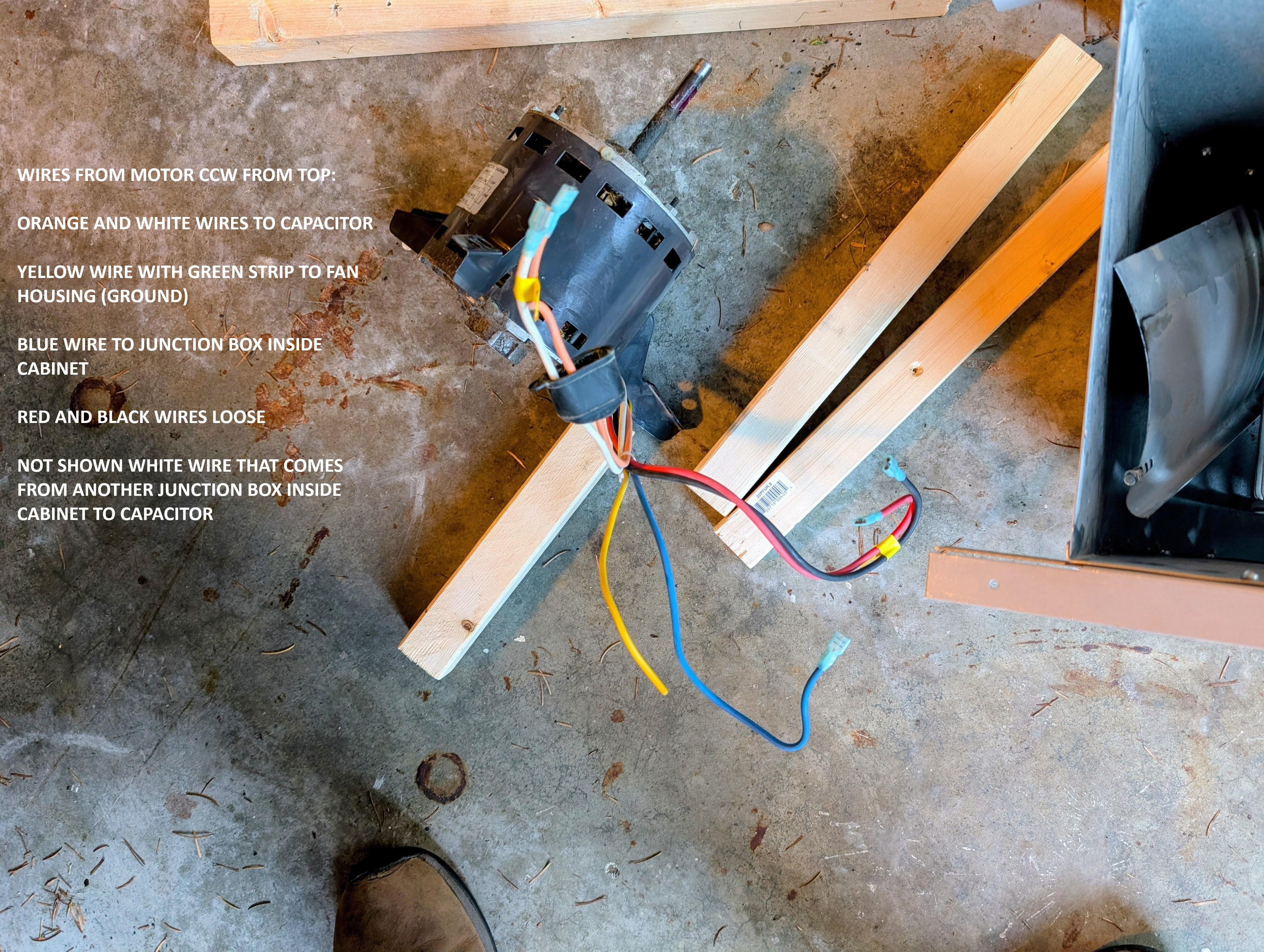
And here are the notations I made when I removed old motor and wiring.
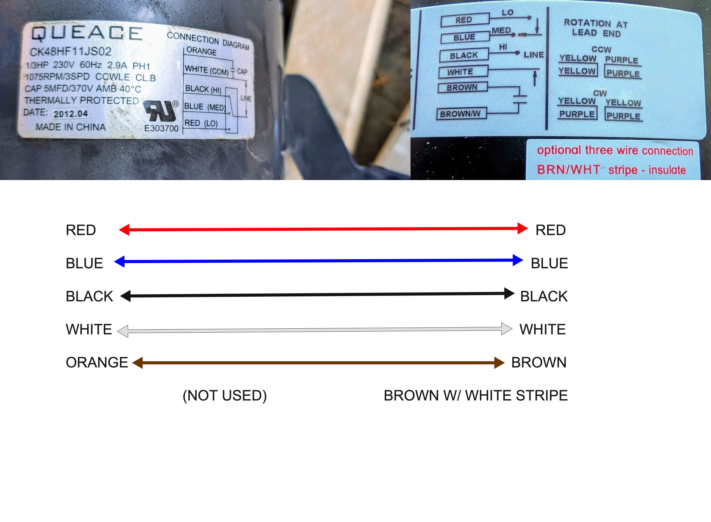
Based on above:
New Brown and Brown/W wires replace old Orange and White wires to CAP.
Blue wire goes to a junction box inside cabinet replacing old Blue wire.
Red and Black wires are loose like old Red and Black wires.
The white wire from another junction box inside the cabinet attaches to other side of the CAP just like before.
Green wire from motor housing replaces old Yellow/G wire to ground motor case to fan housing.
I feel confident this is correct but shant power up until I hear back from the experts.
As always thanks for the help!
Comments
-
The brown with a white stripe is connected to the white wire inside the motor so you need to cap that off just like the red and black wires because you do not want the bare wire end to touch any other wires or metal part inside the cabinet
Edward Young Retired
After you make that expensive repair and you still have the same problem, What will you check next?
0 -
Glad I asked. Should finish install tomorrow.
 1
1 -
One other question the new motor is currently configured for CCW rotation. Does match that the old one?
0 -
Looking at the end of the motor shaft it looks like we want CW rotation? I can feel the fan throw lots more air up manually spinning CW versus the CCW.
0 -
I am confused. Does CCW mean looking at the cover plate of the motor or the output shaft? Old motor seems to indicate it's CCW which agrees with new motor. But looking at the fan side of the motor it seems like CW is what's needed.
0 -
vet motor is listed as
counterclockwise lead end
we need to see the blower wheel
0 -
The way it looks to me, old unit is CCW (CCWLE or CCW Lead End) so the new one should be wired CCW Lead End POV.
 National - U.S. Gas Boiler 45+ Years Old
Steam 300 SQ. FT. - EDR 347
One Pipe System0 -
I saw the CCW on the old motor and the new one is configured for CCW also. So looking at the output shaft (fan) end it's CW which works with the blower.
It's all sort of moot. I hooked everything up and fired it up. It does exactly the same thing hums but doesn't spin.
I also checked the old CAP using the ohm meter test and it is apparently as good as the new one.
So my tech gave me the wrong diagnosis. No surprise.
So now what?
0 -
Well that seems odd. Does the blower assembly spin easily by hand ? I don't recall seeing any pictures of the whole blower assembly, I'll go back and look.
Is the motor getting the proper line voltage ?
National - U.S. Gas Boiler 45+ Years Old
Steam 300 SQ. FT. - EDR 347
One Pipe System0 -
It spins easily by hand. The old motor had lots of end play. The new one has virtually none.
There was previously an intermittent problem where the furnace wouldn't come on. This seemed to go away but then this problem where the motor hums but doesn't spin came along. I hoped this was the cause and the fix for the old problem. But whatever the old problem is was this new problem should be relatively easy to resolve now that it's not intermittent.
I'm all ears.
0 -
I assume both motors would not work with the ''Summer Fan" switch.
Things I would verify.
Does the blower (fan) assembly spin easily by hand ?
Proper motor voltage rating (new motor). I did not see a picture of the full specifications sticker on the new motor.
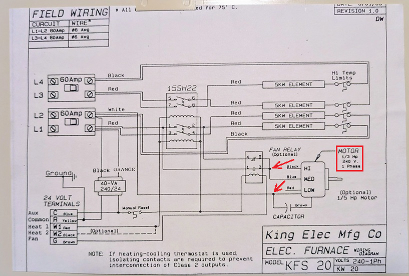
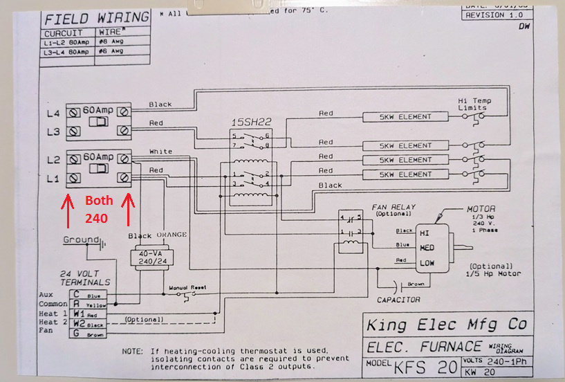
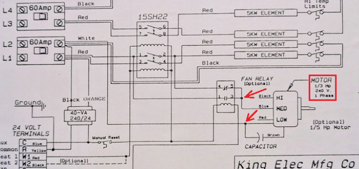
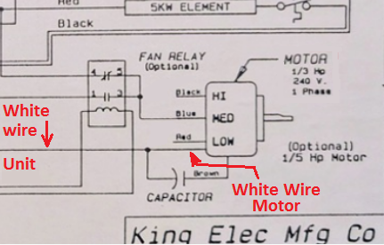
Is there 208 to 250 VAC (not sure what your building Voltage is) at the wires to the motor (Red arrows) I added to to the drawing. Or in other words the voltage found at L1 to L2 should be at the motor when the motor is expected to be running.
 National - U.S. Gas Boiler 45+ Years Old
Steam 300 SQ. FT. - EDR 347
One Pipe System0 -
Correct the old motor wouldn't run on summer fan and neither does the new one.
The old motor spun freely but had lots of free play on shaft end. New motoer spins freely but doesn't have any free play.
My house voltage is 120v (110v whatever). There are 2 lines coming from the house panel to the furnace to get the 240v.
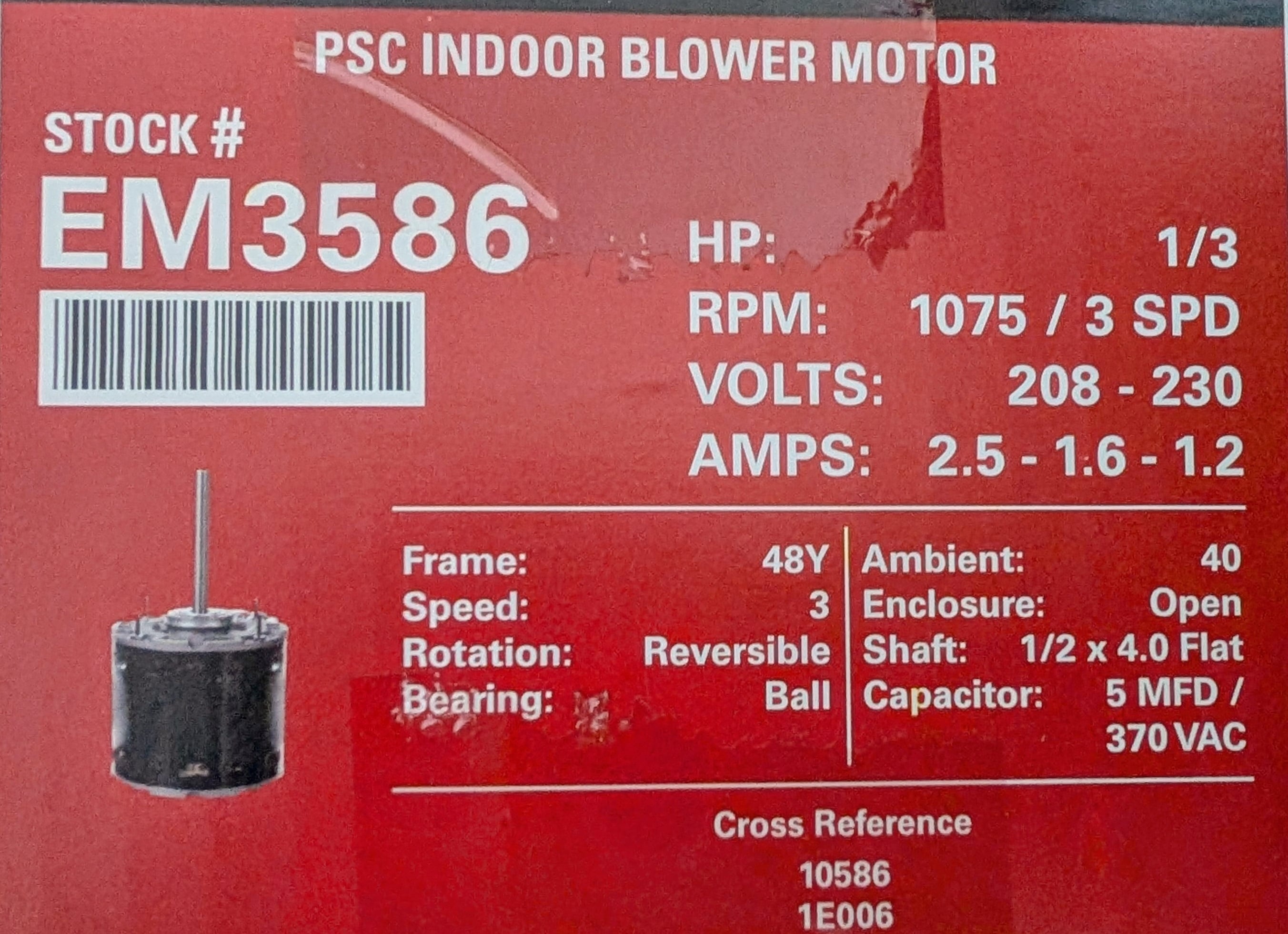
This is label on motor box I hope that answers your question. So if I connect AC volt meter to white wire at CAP and the blue wire at the junction box I should see 240v?
There was discussion previously of potential bad sequencer. I can't find motor hums but doesn't spin as a symptom of bad seq online. But the power to the blue line is downstream of the seq in the diagram. Just asking.
0 -
Is this still true ?
 National - U.S. Gas Boiler 45+ Years Old
Steam 300 SQ. FT. - EDR 347
One Pipe System0 -
The unit not starting problem seemed to go away. But when it was happening the summer fan always worked.
Then after the intemittent not starting problem seemed to go away one day the motor would hum but not spin. It actually would hum then start for a bit but the humming got longer and finally it wouldn't start. The summer fan stopped working too. And doesn't work with the new motor either.
I ask again is there anyway bad sequencer could cause this?
0 -
In "Summer Fan" Mode the sequencer relay is bypassed, as far as the fan is concerned. When the Fan relay is at rest the fan is powered only when the first stage of the sequencer relay is active. During "Summer Fan" Mode it gets the fan power before the sequencer relay.
Since the "Summer Fan" Mode no longer works, and assuming it is actually the same original defect that has now gotten worse, the common denominator is the power source. The logic here is when calling for heat the load is much greater (heating elements active) than when the just the fan only is activated "Summer Fan" Mode.
I'd be very curious about the L1, L2 circuit breaker integrity. Is there 240 VAC at the L1, L2 terminals and where the White and Red wires come out of the 60 Amp circuit breaker when any load is active ?
 National - U.S. Gas Boiler 45+ Years Old
Steam 300 SQ. FT. - EDR 347
One Pipe System0 -
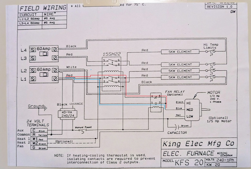
During heat mode the 'switched' portion of the fan power is the Red path through the sequencer and the Normally Closed fan relay contacts. During "Summer Fan" mode (fan relay energized, Normally Closed contacts open and the Normally Open contacts close) the Blue path is used, bypassing the sequencer relay.
Since both modes now don't work, I think it is a power issue and not the sequencer relay. Like the 60 Amp local breaker or even maybe the circuit breaker in the buildings electrical panel. Also keeping in mind historically flipping the local 60 Amp breaker restored operation I'd focus on that.
 National - U.S. Gas Boiler 45+ Years Old
Steam 300 SQ. FT. - EDR 347
One Pipe System0 -
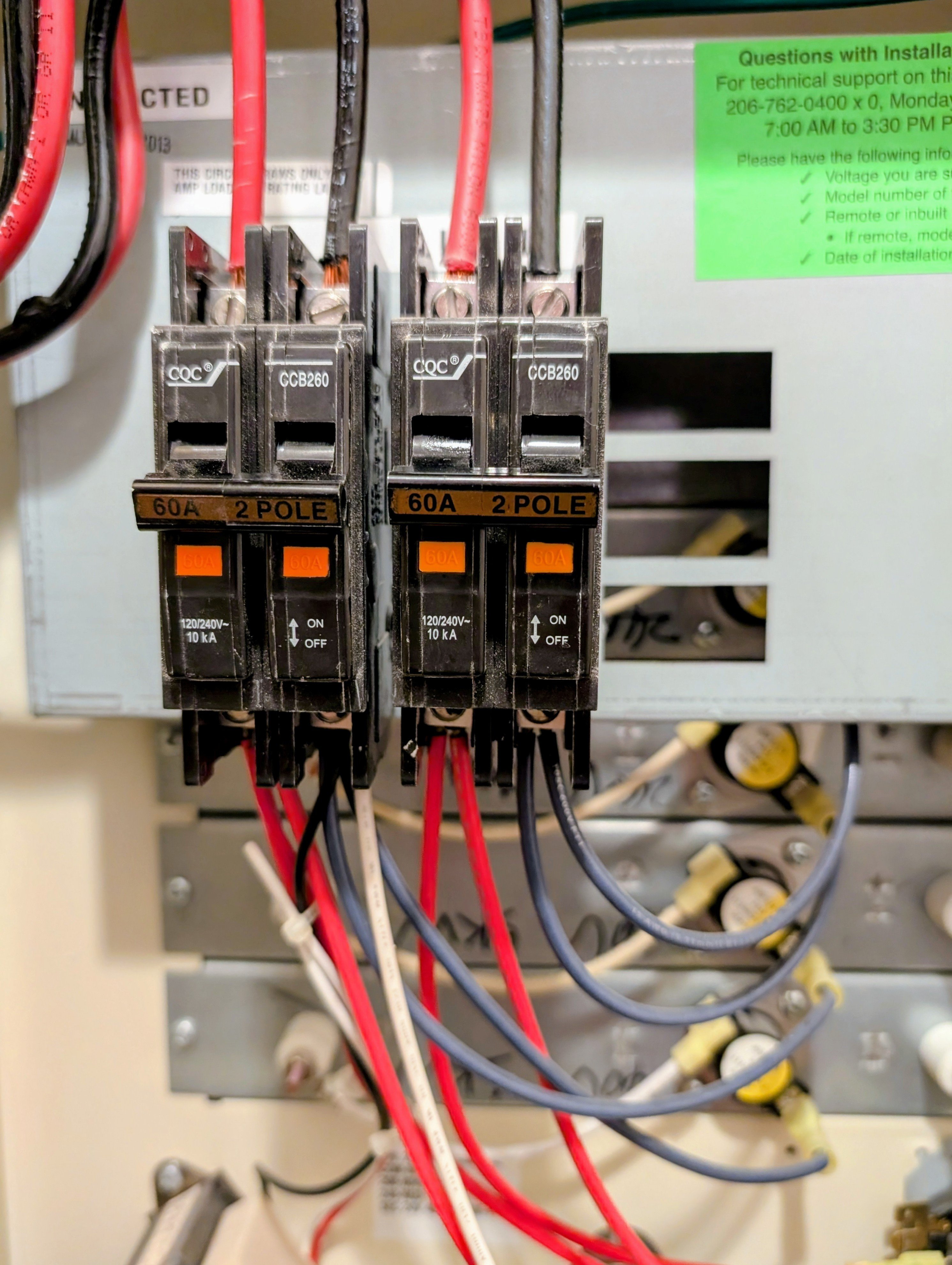
So I set my voltmeter to AC volts and a range that includes 240 volts. Then I touch either end to the red wire screw at top and the other end to the black wire screw? And then repeat for the connections on the bottom of the breaker?
You can't see in photo but circuits are LI thru L4 for left to right.
One other note we had the house panel replaced in the last year or two. There was a breaker box in the furnace closet also but they bypassed it, no more breakers just a junction.
0 -
Get some wire and hook the fan motor to 240 volt directly without going through any relays or controls and see if it runs.
As far a s motor rotation goes the standard always was checking the rotation by looking at the shaft end of the motor.
However some motors are marked CCW LE or CW LE which means counter clockwise lead end or clockwise lead end respectively.
 1
1 -
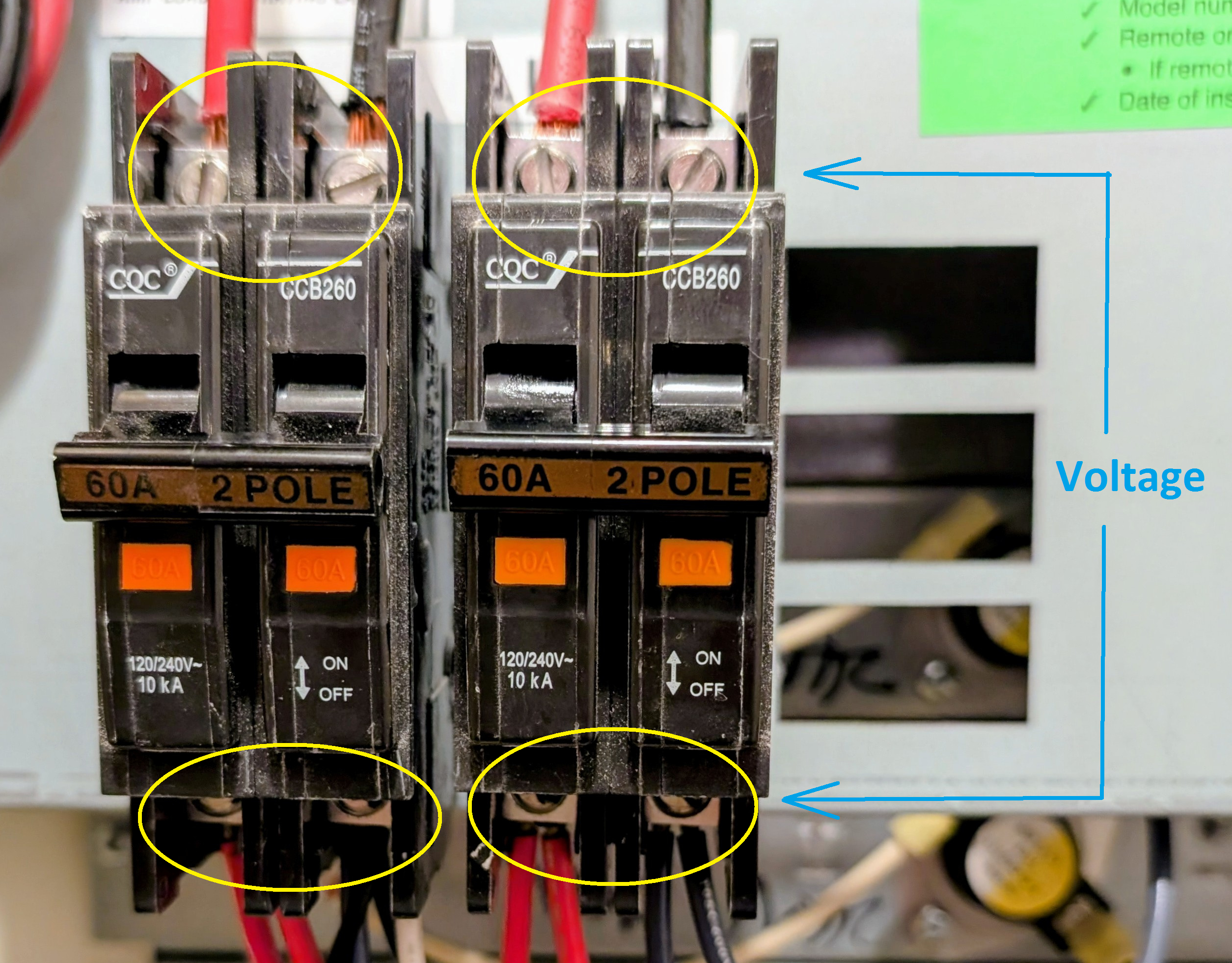
Within each Yellow circle there should be 240 VAC under load with the unit working (trying to work). You can also measure (under load) the voltage drop across each circuit breaker contacts (4 vertical paths, blue arrows). The voltage under load should be very low across the contacts. I suspect you have an issue with the L1, L2 left most breaker or maybe in the former bypassed breaker connections. I'm thinking the defect issue now should be electrically very obvious now that the unit is is mostly inoperable.
 National - U.S. Gas Boiler 45+ Years Old
Steam 300 SQ. FT. - EDR 347
One Pipe System0 -
The voltage at the top was 240v at LI/L2 and L3/L4. Ditto for the bottom. The was all done with the fan off and the thermostat off.
I turned the fan on and got the same result. The voltage from top to bottom on each breaker with the fan on was zero.
I confess I'm a little nervous taking these readings.
Also for grins I set the thermostat to 80 and turned it on. Unit didn't start but I heard some clicking noises inside.
Guess I just need to find competent techs.
I did the resistance check on both my CAPs old and new with my ohm meter. Was told there's a possibility the bad motor ruined both my old and new CAPs and the ohm meter check isn't definitive. Since the CAP was so cheap maybe I'll try another one. Probably get it faster than I can find a tech I trust.
Also, I've had it happen that i replaced a bad part with another bad new part. Not totally impossible but unlikely.
Regardless thanks for the help.
0 -
Better a bit nervous than complacent. As @EBEBRATT-Ed stated above you could independently test the blower motor.
Was the 240 VAC ever measured at the motor line voltage leads ? Heat mode and in "Summer Fan" mode ?
 National - U.S. Gas Boiler 45+ Years Old
Steam 300 SQ. FT. - EDR 347
One Pipe System0 -
Do any of the heating elements ever warm up ?
National - U.S. Gas Boiler 45+ Years Old
Steam 300 SQ. FT. - EDR 347
One Pipe System0 -
I can check that I guess. but white wire from cabinet goes to the cap. Then white wire and brown wire go from other side of CAP into motor. So I check voltage between white wire that goes to cap and blue wire that goes to motor?
I don't know if the elements heat up.
0 -
" Unit didn't start but I heard some clicking noises inside. "
Could that have been the heating elements heating up ?
I probably would have tested the motor before I installed it. I hate to do things twice. Been screwed by bad parts too many times before.
National - U.S. Gas Boiler 45+ Years Old
Steam 300 SQ. FT. - EDR 347
One Pipe System0 -
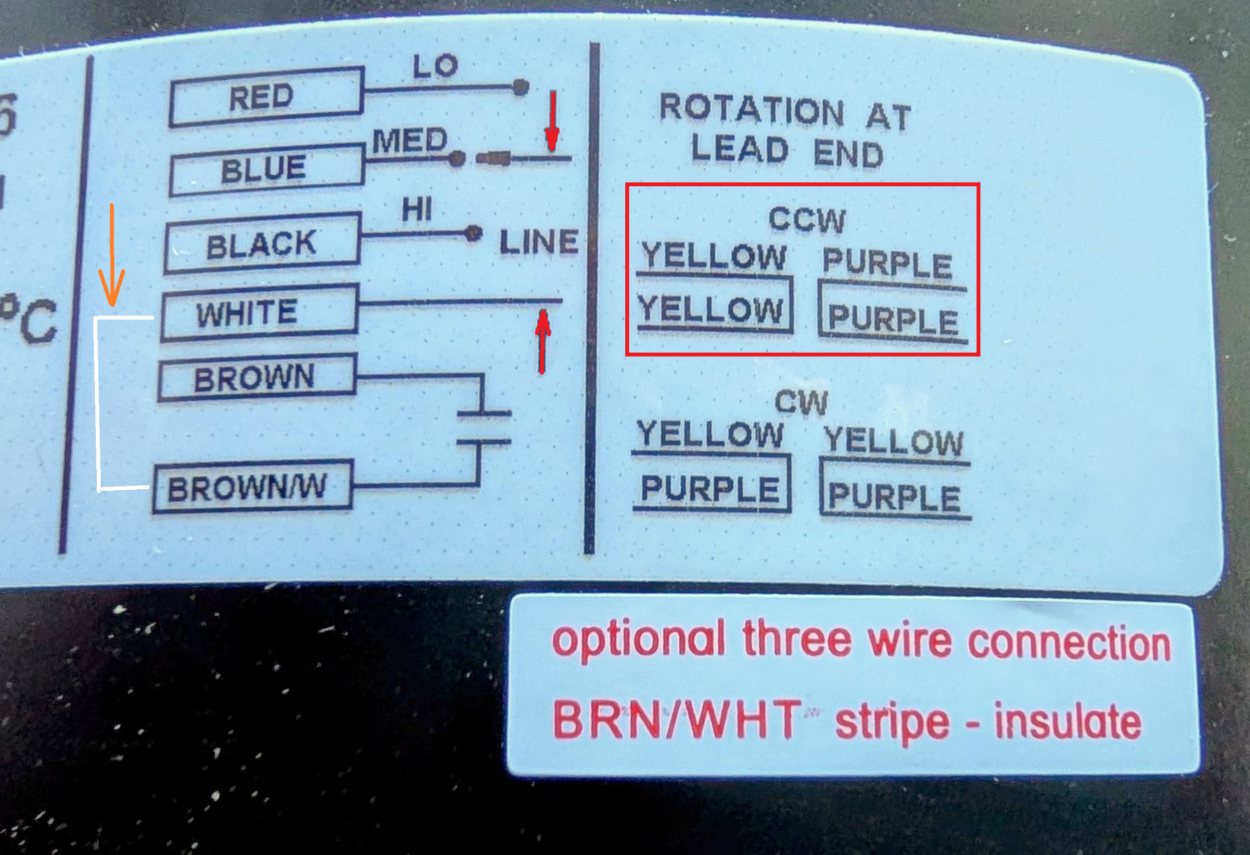
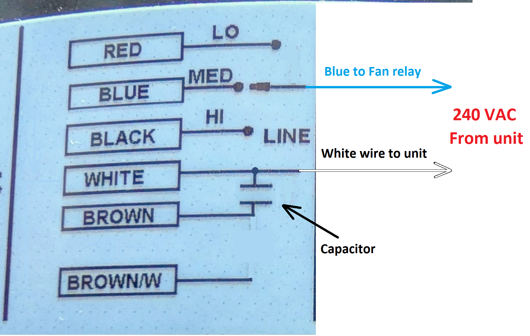
The label "optional three wire connection BRN/WHT stripe - insulate"
Does seem to imply the BROWN/W is connected to the WHITE inside the motor. Like the white wire that the Orange arrow points to. With the CCW wires connected I'd apply or at least measure 240 VAC to the line wires (Red arrows), WHITE and what ever speed you pick, you may want to try other speeds also.
So you presently have the Cap. connected between the BROWN and the WHITE wires and the BROWN/W is insulated.
Yes 240 VAC to the WHITE and BLUE wire if you selected the Medium speed.
 National - U.S. Gas Boiler 45+ Years Old
Steam 300 SQ. FT. - EDR 347
One Pipe System0 -
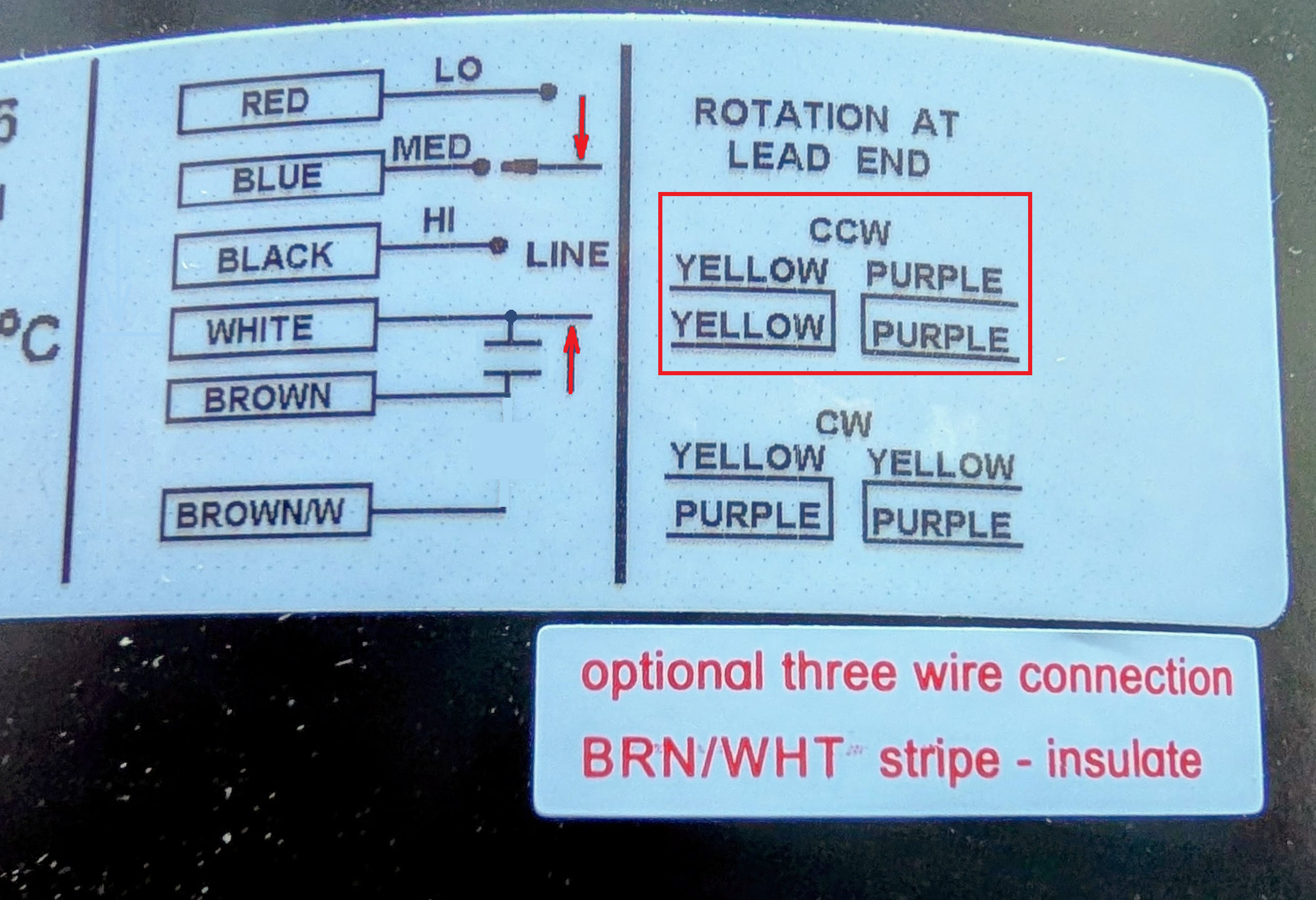
Effectively it would be like this with the "three wire connection". You could try the 4 wire connection to see if it makes a difference. Either way, I'd make sure the motor is getting power.
 National - U.S. Gas Boiler 45+ Years Old
Steam 300 SQ. FT. - EDR 347
One Pipe System0 -
It just seems odd that both motors have the same symptoms. I'm not convinced that the old motor killed both capacitors, although I suppose it is not impossible.
National - U.S. Gas Boiler 45+ Years Old
Steam 300 SQ. FT. - EDR 347
One Pipe System0 -
The brown/w wire is insulated. Checked across the white wire to the blue wire got 240v with the summer fan switch on. Got zero with the switch off.
0 -
Can I text the motor by bypassing the CAP? Connect the white wire from the unit directly to the white wire on the motor? My volt ohm meter doesn't seem to have a capacitance test function.
0 -
To test the motor that is not on the equipment now, you need to find 220 volts somewhere in your home that you can plug into. An electric clothes dryer, an electric range, the electric line that goes to the air handler. Then I would measure the electricity with an electric meter. You must have a "known good" source of 220 volts.
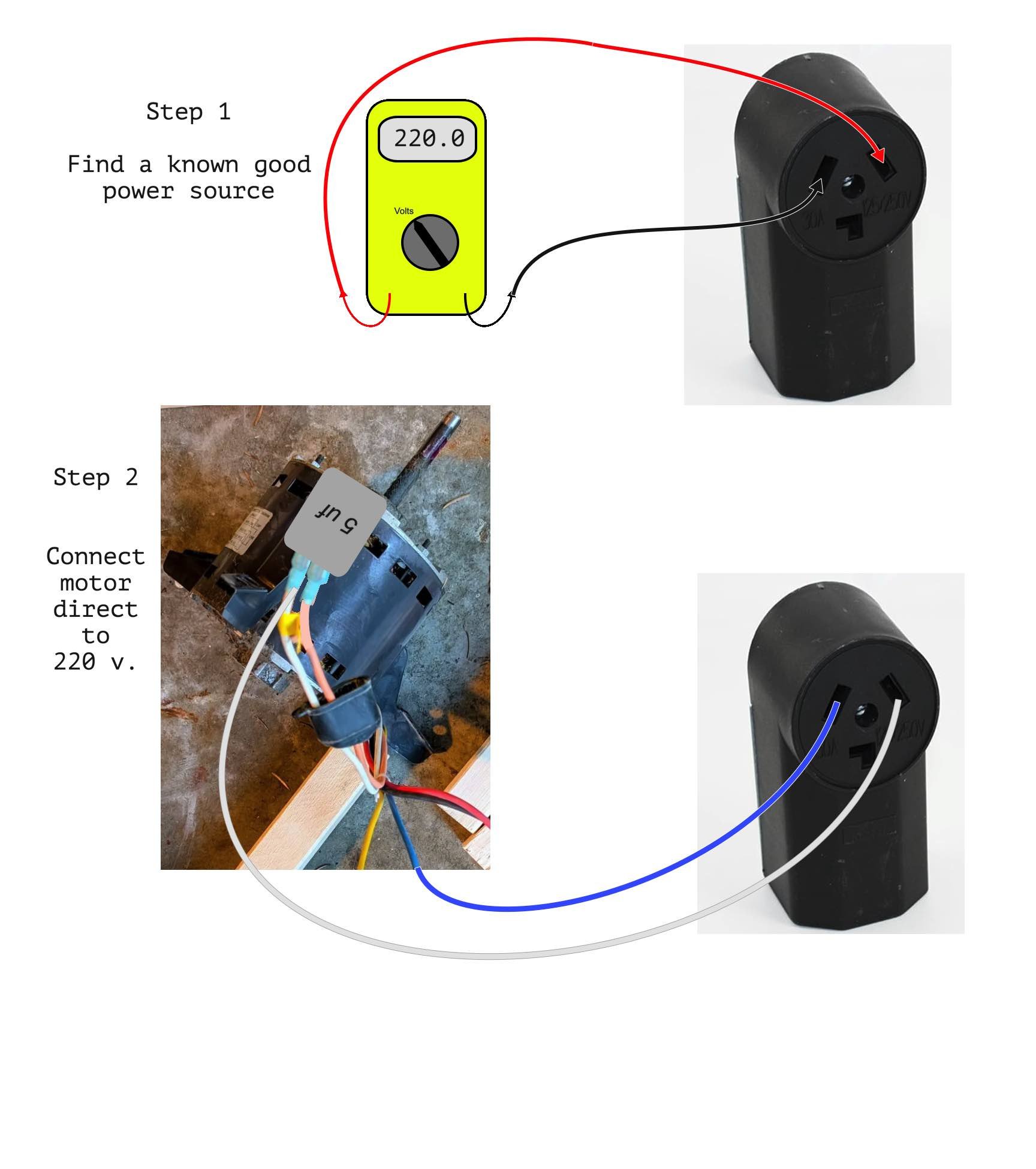
Then step 3.
Read my tag line about what you will check next.
Edward Young Retired
After you make that expensive repair and you still have the same problem, What will you check next?
0 -
The step three I mentioned is to check that you have 220 volts at the air handler with a meter. on the leads that are supposed to operate the motor.
Edward Young Retired
After you make that expensive repair and you still have the same problem, What will you check next?
0 -
It seems like the motor is getting appropriate power.
Are you sure the CCW connections are intact ?
Just in case the sticker is not accurate you could connect the capacitor to the Brown and Brown/White wires.
And as you suggested try another Capacitor. That may be the most inexpensive, quick option.
" Got zero with the switch off. " If the thermostat was turned up or jumpered at the furnace terminals you should get 240 at the motor also.
National - U.S. Gas Boiler 45+ Years Old
Steam 300 SQ. FT. - EDR 347
One Pipe System0 -
OK had it for today. Tomorrow I will see if I get power with the thermostat.
0 -
The Capacitor needs to be in the circuit and properly connected. It provides the needed phase shift in the magnetic flux to start the motor. Depending on the motor design it may also enhance the running torque.
" Connect the white wire from the unit directly to the white wire on the motor? "
Is that not how it is connected now ?
The motor white wire should be connected to the units white wire, just like it originally was.
 National - U.S. Gas Boiler 45+ Years Old
Steam 300 SQ. FT. - EDR 347
One Pipe System0 -
I just meant the power to the motor should also be present when the thermostat calls for heat. The fact that the "Summer Fan" switch does apply appropriate power to the fan, the fan should work.
" Connect the white wire from the unit directly to the white wire on the motor? "
Looks like the white wire from the unit is connected to the white wire of the motor at the capacitor. That should be the same with the new motor. 3 wire connection method.
OR with the 4 wire method the capacitor connects to the Brown and Brown/White wires, the unit's white wire to the motor's white wire and the Blue wire (medium speed) to the fan relay.
 National - U.S. Gas Boiler 45+ Years Old
Steam 300 SQ. FT. - EDR 347
One Pipe System0 -
Three wire method. Blue, White, Brown. Blue and White receive the 240 VAC from the unit. White and the Brown connect to the capacitor.
 National - U.S. Gas Boiler 45+ Years Old
Steam 300 SQ. FT. - EDR 347
One Pipe System0 -
OK, my daughter in law's father is a retired electrician. Not a furnace repair person but he has knowledge, experience and tools that I am lacking.
He found out we didn't have heat so he drove 2 hours to look at the furnace. He made the following change.

Now the motor turns and the furnace appears to be working. Not only is it working but it's so quite at first I thought it still wasn't working. Previously with the old motor you could tell when the heat was on anywhere in the house from the noise.
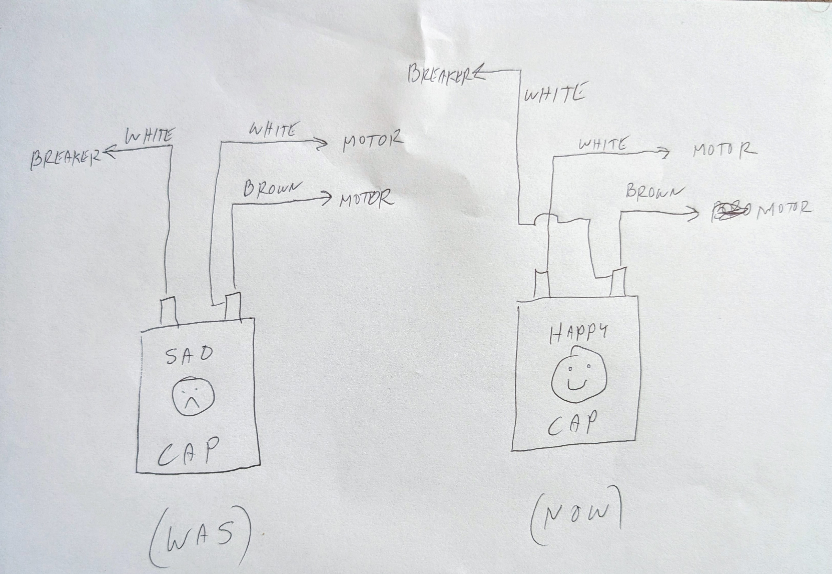
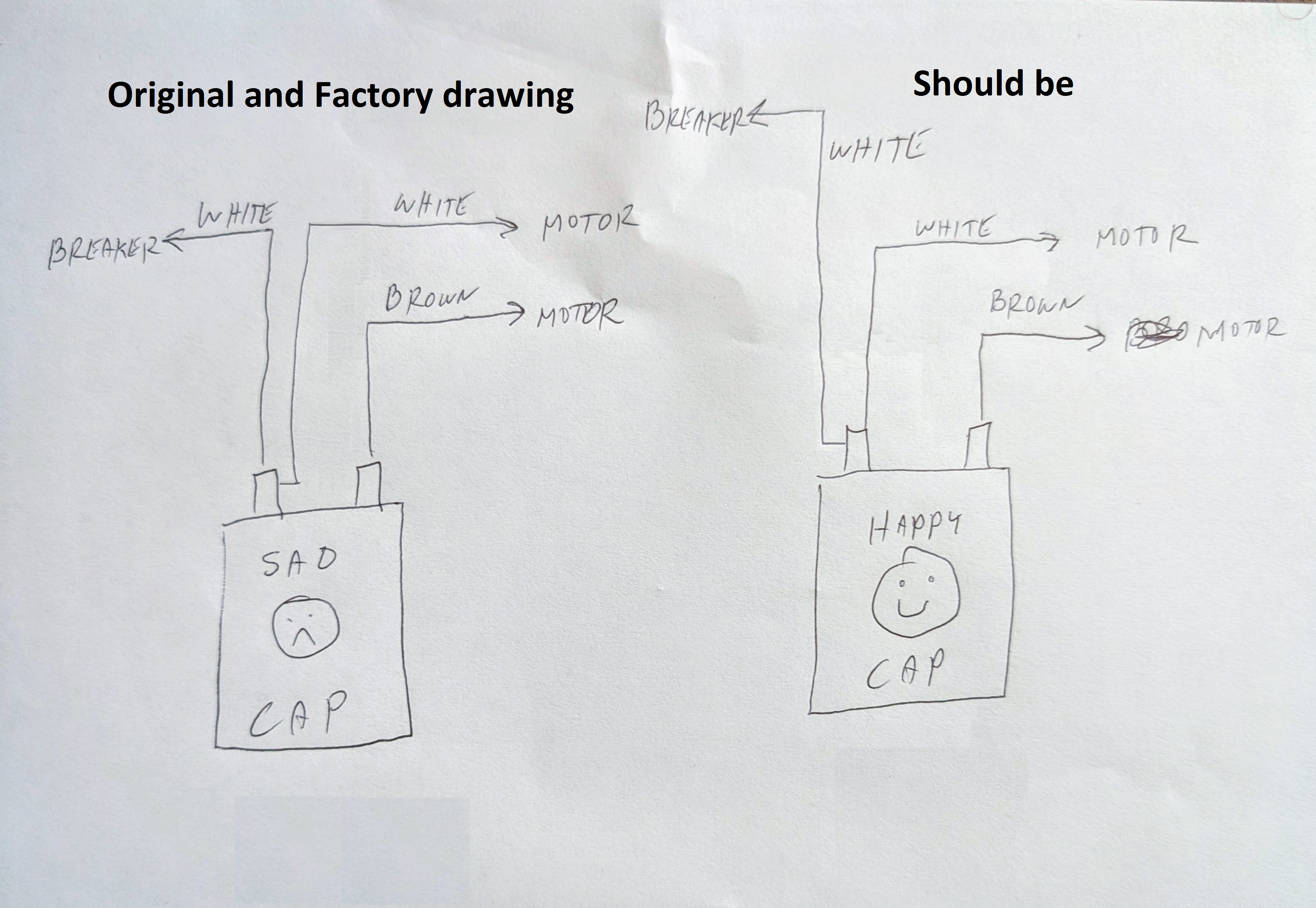
So hoping me having it hooked up wrong didn't hurt anything. But I could swear I matched the old wiring and still don't understand the wiring diagram and the CAP connections but hard to argue with success.
My daughter in law's father also told me the sequencer has 2 bad switches.
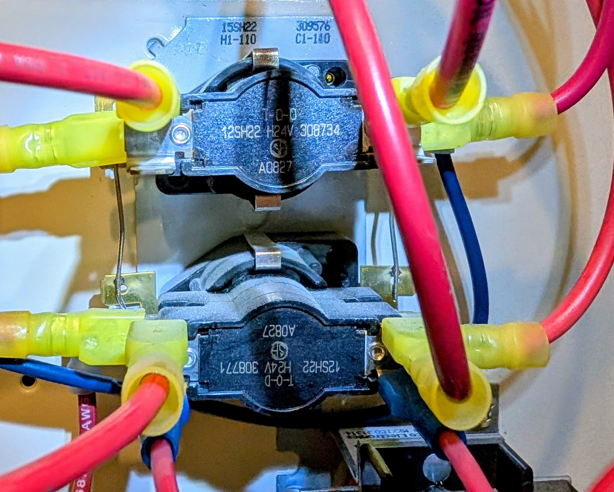
Based on the 15SH22 number on the unit I found this:
Is this the correct replacement sequencer?
My daughter in law's father said he thought I could replace the unit myself. Just take the old unit loose, swap wires to the new unit one by one, attach new unit.
Again thanks for all your help past and present.
0 -
Well I don't agree with any of the present assessment and information. Since it does not agree with any of the documentation. And if you actually have heat at least one of the two sections of the sequencer work since the first stage of the sequencer turns the blower on and the first stage of the heat.
The way it is connected now I bet the motor is running slower and may overheat the motor and / or Capacitor and not either manufacture's intended wiring. It appears you have effectively switched the motor's main winding with the start / run winding. This may overheat the motor and / or the Capacitor.
 National - U.S. Gas Boiler 45+ Years Old
Steam 300 SQ. FT. - EDR 347
One Pipe System0 -
OK I'll go swap it. I think we tried it and that looks like what I think the wiring diagram says but it didn't work. Not hard to do a quick swap.
0 -
He said 2 element switches were working and 2 weren't.
0


Categories
- All Categories
- 87.7K THE MAIN WALL
- 3.3K A-C, Heat Pumps & Refrigeration
- 59 Biomass
- 430 Carbon Monoxide Awareness
- 129 Chimneys & Flues
- 2.2K Domestic Hot Water
- 5.9K Gas Heating
- 122 Geothermal
- 170 Indoor-Air Quality
- 3.8K Oil Heating
- 79 Pipe Deterioration
- 1.1K Plumbing
- 6.6K Radiant Heating
- 396 Solar
- 16K Strictly Steam
- 3.5K Thermostats and Controls
- 56 Water Quality
- 51 Industry Classes
- 51 Job Opportunities
- 17 Recall Announcements