Super hot mini boiler no power

I have no power to my mini gas boiler. I have checked the breaker, fuses, wiring, and reset my dampner switch, and flame roll out. The pilot light is lit. But no green or yellow lights on the control panel. So could my control board be shot or should I check other things on my control panel first? Like the relay?
Comments
-
Step 1 — did you actually check the voltage provided to the unit? And you have 120 volts hot to neutral and hot to ground? Multimeter?
OK. I assume you did.
Then check the manual and see if there is a user replaceable fuse on the control board. There sometimes is. Of course it would be nice to know why it blew, if it did, but…
Br. Jamie, osb
Building superintendent/caretaker, 7200 sq. ft. historic house museum with dependencies in New England0 -
Can you post some pictures of your control panel and boiler here?
8.33 lbs./gal. x 60 min./hr. x 20°ΔT = 10,000 BTU's/hour
Two btu per sq ft for degree difference for a slab0 -


I am borrow my brother voltage tester tomorrow but I have checked and replaced the fuses.
0 -
No wires are lose or fraid
0 -
Seems the troubleshooting guide is a bit vague in your case.

I believe this is the wiring diagram. There is a 2.5 Amp fuse on the 24 VAC side. A multimeter could be used to verify the power.

https://alliedboilers.com/wp-content/ProductDocuments/MG/MG%20Installation%20%26%20Service%20Manual%20%28S9361A%29.pdf
National - U.S. Gas Boiler 45+ Years Old
Steam 300 SQ. FT. - EDR 347
One Pipe System 1
1 -
Yes agreed the manual does not provide much help. I have checked the 2.5 fuse and replaced it. Still no power. I will get a voltage reader. Not sure where to check or start to see if there is power going into the boiler. I have been told to check the plug that is connected to the breaker and Maybe that is the problem but I not sure if that shows power where else to check on the control panel. Suggestions?
0 -
I would like to see what the pressure gauge reads. Some boilers will not fire if the pressure in the sys fall below a certain pressure. If the boiler is corded, unplug the boiler and plug a lamp into the socket and see if it lights. If the boiler is hard wired, look for a switch box with a switch and make sure it is on. Report back.
If a breaker in the breaker panel trips for the boiler circuit, you, in most cases, have to turn the breaker switch to the fully off position before turning it fully on. Breakers do trip mid-position between on and off and just switching it on will not reset it.
0 -
I would expect 120 VAC and 24 VAC where noted in the 1st image. If your system has a LWCO (Low Water Cut Off) that may interrupt the 120 VAC from getting to this board (see note in second image). What voltage you find (or not find) will determine the troubleshooting direction to go in.

 National - U.S. Gas Boiler 45+ Years Old
Steam 300 SQ. FT. - EDR 347
One Pipe System0 -
I'm assuming you saw this video, if not it may help identify some of the supporting equipment like the LWCO.
National - U.S. Gas Boiler 45+ Years Old
Steam 300 SQ. FT. - EDR 347
One Pipe System0 -
I have checked and there is power to the unit. As per above photo. I have power to the 120 vac but not the 24 vac. Do I need to replace that 25 vac?
0 -
OK if there is 120 VAC across L1 and L2 and no 24 VAC, if you have not, I would also check the 5 Amp fuse to the left of the transformer (the big thing in the middle of the board). It is defined as a 'Pump Fuse' on the schematic, however it is not shown on the ladder diagram, so I have little confidence of its placement in the circuit.
I would double check all measurements.
Other than the fuse with the symptoms of 120 VAC across L1 and L2 and no 24 VAC on the other connector the most likely cause is the transformer failed, or a failed solder connection(s) on the circuit board could also cause this symptom. The board would have to be removed to inspect the solder joints for cracks also.
With the ohmmeter function of the multimeter and the system power OFF (circuit breaker OFF), I would verify the continuity of the primary and secondary of the transformer, some things may have to be disconnected and/or the board removed to get an accurate reading of the transformer.
It is possible to replace the transformer if a suitable replacement one can be found, also failed solder joints can be re-soldered. I suspect that whole board is proprietary to the boiler manufacture, so if replacement of the board is the best remedy for you, you may have to contact the manufacture or their parts distributor.
Just saying; If it was my boiler and it is a failed transformer and I could not find a suitable replacement of the circuit board mounted transformer. I would remove the failed transformer and connect up a generic 120 VAC to 24 VAC transformer and mount it elsewhere in a safe place. I can easily do that type of repair, also I realize others can't or are not comfortable doing so. I suspect a typical HVAC pro may not be comfortable with that type of repair, they would want to replace the board or the whole boiler if the board is not available any more.
National - U.S. Gas Boiler 45+ Years Old
Steam 300 SQ. FT. - EDR 347
One Pipe System 1
1 -


These are the pictures of what I found for power. I have checked the fuses and they are good. And when I put the voltage tester to the transformer it also went red showing power. So by the last comment. It sounds like the board may need to be replace. But again. I am just guessing and I may need to take the board off and look at the soldering joints. Again any suggestions would be so greatly appreciated.
Thanks
0 -

 0
0 -
Um… well, that kind of "voltae tester" will show that there is 110 at that wire. It will NOT show 24 volts, nor will it show whether there is a connection back to the panel on the neutral wire.
If you do not have a multimeter and know how to use it, this might be a good time to learn. So far, all that you have proved is that the hot at the board is probably hot.
Br. Jamie, osb
Building superintendent/caretaker, 7200 sq. ft. historic house museum with dependencies in New England0 -
Well using a non-contact tester may not be very conclusive, I would NOT recommended that for the type of testing / troubleshooting you need to do. You need a multimeter to get real voltage readings.
National - U.S. Gas Boiler 45+ Years Old
Steam 300 SQ. FT. - EDR 347
One Pipe System0 -
The testing you have done so far may be meaningless, you need a multimeter and be able to use it correctly.
National - U.S. Gas Boiler 45+ Years Old
Steam 300 SQ. FT. - EDR 347
One Pipe System 1
1 -
I'm just wondering why there are so many yellow wire nuts there in that last picture. Seems like that boiler should have a landing terminal for every wire. Regardless, I would turn off the power and check to see if any wires have become disconnected from the wire nut connections.
8.33 lbs./gal. x 60 min./hr. x 20°ΔT = 10,000 BTU's/hour
Two btu per sq ft for degree difference for a slab0 -
Also here you are not probing the points I specified. The arrows I added to your picture (above) were to measure the voltage across the top two wires at that connector, back-probing the connector pins. With electrical troubleshooting, without making the correct and accurate measurements with the correct equipment any conclusions are basically useless, since you really don't know what is actually going on in the circuit.
" I will get a voltage reader " In my mind that would be a meter not a non-contact type tester, I guess I got blindsided here, good you posted the pictures.

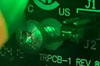
Kind of wondering why this screw looks loose. If the board falls out it may cause other damage.
 National - U.S. Gas Boiler 45+ Years Old
Steam 300 SQ. FT. - EDR 347
One Pipe System0 -
Seems J1 and J2 are set wrong too. Won't solve the power issue, but kind of make me wonder what else is not quite correct. With J2 in place it bypasses the functionality of the zone valve end switches.


 National - U.S. Gas Boiler 45+ Years Old
Steam 300 SQ. FT. - EDR 347
One Pipe System0 -
I will go buy a multimeter tomorrow. And look at the screw the j1 and j2. I appreciate everyone for look and suggesting what to look at.
0 -
Before touching that screw disconnect the power!
Please
Be very very careful in there, a lot can hurt you in a heartbeat!
0 -
This wire not being where you would expect it to be, may also be a clue of failing solder joints (or someone just being weird). May have been a quick inexpensive repair to get that zone working again.
 National - U.S. Gas Boiler 45+ Years Old
Steam 300 SQ. FT. - EDR 347
One Pipe System1 -
So I got a multimeter and the 120v is only read 12 and the 24v is only read 1.2. So it seems i am not getting enough power. So would that be a bad relay?
0 -
" So would that be a bad relay? "
If it was a relay it would be in the LWCO unit.
Well those readings seem odd in the respect that 12 VAC is about 1/10 of what it should be, with that I would expect the 24 VAC to also be 1/10 of what it should be, or 2.4 VAC and not 1.2 VAC.
You did verify the meter reads 120 VAC correctly with a known good point like a receptacle that is known to work correctly ? Nothing worse than your test equipment deceiving you.
Anyway assuming the 12 VAC is an accurate measurement across L1 and L2 the defect would be between that connection point and the circuit breaker panel box. Since the non-contact tester seemed to be happy with the Hot wire potential being present I would expect the defect is with the Neutral wire. Also the non-contact tester seemed to alert on L2 which should be the Neutral wire, although the alert can be ambiguous unless close attention to detail is observed and also the installer may have reversed the wiring to L1 and L2.
Typically in this case L1 is the Hot wire and L2 is the Neutral wire. In North America the Neutral is bonded to Ground at the main electrical service equipment. Another test (if the home's electrical system is not too old, no grounding) to help verify the low voltage situation and better understand where the defect is, is to a use a good Ground to make the measurements as illustrated below. It's like a second opinion.
Using a good Ground as a reference for the meter (possibly the boiler's jacket or a cold water pipe) L1 should have 120 VAC (the Hot wire) an L2 near 0 (zero) (the Neutral wire).
I suspect, since your non-contact tester was alerting on L2 (your picture) the Neutral wire has a loose connection somewhere. In which case I would suspect with the meter using a Ground as a reference L1 will have 120 VAC to Ground and L2 will have about 108 VAC (120 minus 12) to Ground, when it should be zero AC Volts. So there is a 108 VAC drop across a loose connection with the Neutral wire between the L2 and circuit breaker panel box's Neutral Buss Bar.
If the AC power passes through the LWCO I would check in there and also any wire nuts associated to the AC power wiring inside the boiler's cabinet.
With the boiler's power off (the Boiler's circuit breaker OFF) inspect and verify the integrity of the AC power wiring, there may just be a loose connection that needs securing.

 National - U.S. Gas Boiler 45+ Years Old
Steam 300 SQ. FT. - EDR 347
One Pipe System1 -
Also, be sure your multimeter is set correctly. The black probe gets plugged into the black port, obviously, but there are usually two different ports for the red probe, depending on what you're measuring. For voltage, you want the red probe plugged into the red port marked "V".
There will also be two different dial positions for measuring voltage, one for DC (direct current) and one for AC (alternating current). You want the AC voltage position, which will be marked by a V with a wavy line above it. You don't want the V with the straight and dashed lines, which is DC voltage.
0 -
Only test to Ground to confirme the circuit is dead!
Always test between Hot & N or Hot & Hot depending on the voltage!
0 -
With measuring AC Voltage the Red and the Black probes can be reversed it make little difference since it is AC. Try it.
" Only test to Ground to confirme the circuit is dead! "
Not true; Measuring to Equipment Ground (using the equipment Ground as a reference for the multimeter) is a common diagnostic technique. One of the easiest ways to verify a compromised Neural wire. You do need the load connected.
If you just measure Hot to Neutral (L1 to L2) like Babyblues did and she measured 12 VAC, which wire is compromised ? You have no way to tell. Using the Equipment Ground (if viable) gives you a second opinion, easy nothing new here.
National - U.S. Gas Boiler 45+ Years Old
Steam 300 SQ. FT. - EDR 347
One Pipe System0 -
@109A_5 said:
"With measuring AC Voltage the Red and the Black probes can be reversed it make little difference since it is AC. Try it."
True, but I don't recommend that practice for people who may not be familiar with multimeters. The main point was that she needs to make sure the probes are plugged into the correct ports for volts, not amps.
0 -
I disagree! What happens if there a bad neutral, at the unit, in a junction box, in the panel? You get Zero but still show potential to ground!
0 -
Whoa. There are three measurements you need, with the unit powered up (not necessarily on at this point).
All three are AC volts, and hopefully the meter is autoranging — most newer ones are.
First. Hot to ground. Should be 120 volts, but could be as low as 110 volts or as much as 125.
Second. Hot to neutral. Should be the same as hot to ground, plus or minus 2 volts.
Third. Neutral to ground. Should be less than 2 volts.
You don't have to do them in that order, but you need to do all three.
Any other voltage reading indicates a bad or open connection, compromised wire, or faulty fuse or circuit breaker somewhere. Unless you are pretty happy with electricity, it might be time to find an electrician…
Br. Jamie, osb
Building superintendent/caretaker, 7200 sq. ft. historic house museum with dependencies in New England
 3
3


Categories
- All Categories
- 87.7K THE MAIN WALL
- 3.3K A-C, Heat Pumps & Refrigeration
- 59 Biomass
- 430 Carbon Monoxide Awareness
- 129 Chimneys & Flues
- 2.2K Domestic Hot Water
- 5.9K Gas Heating
- 122 Geothermal
- 170 Indoor-Air Quality
- 3.8K Oil Heating
- 79 Pipe Deterioration
- 1.1K Plumbing
- 6.6K Radiant Heating
- 396 Solar
- 16K Strictly Steam
- 3.5K Thermostats and Controls
- 56 Water Quality
- 51 Industry Classes
- 51 Job Opportunities
- 17 Recall Announcements