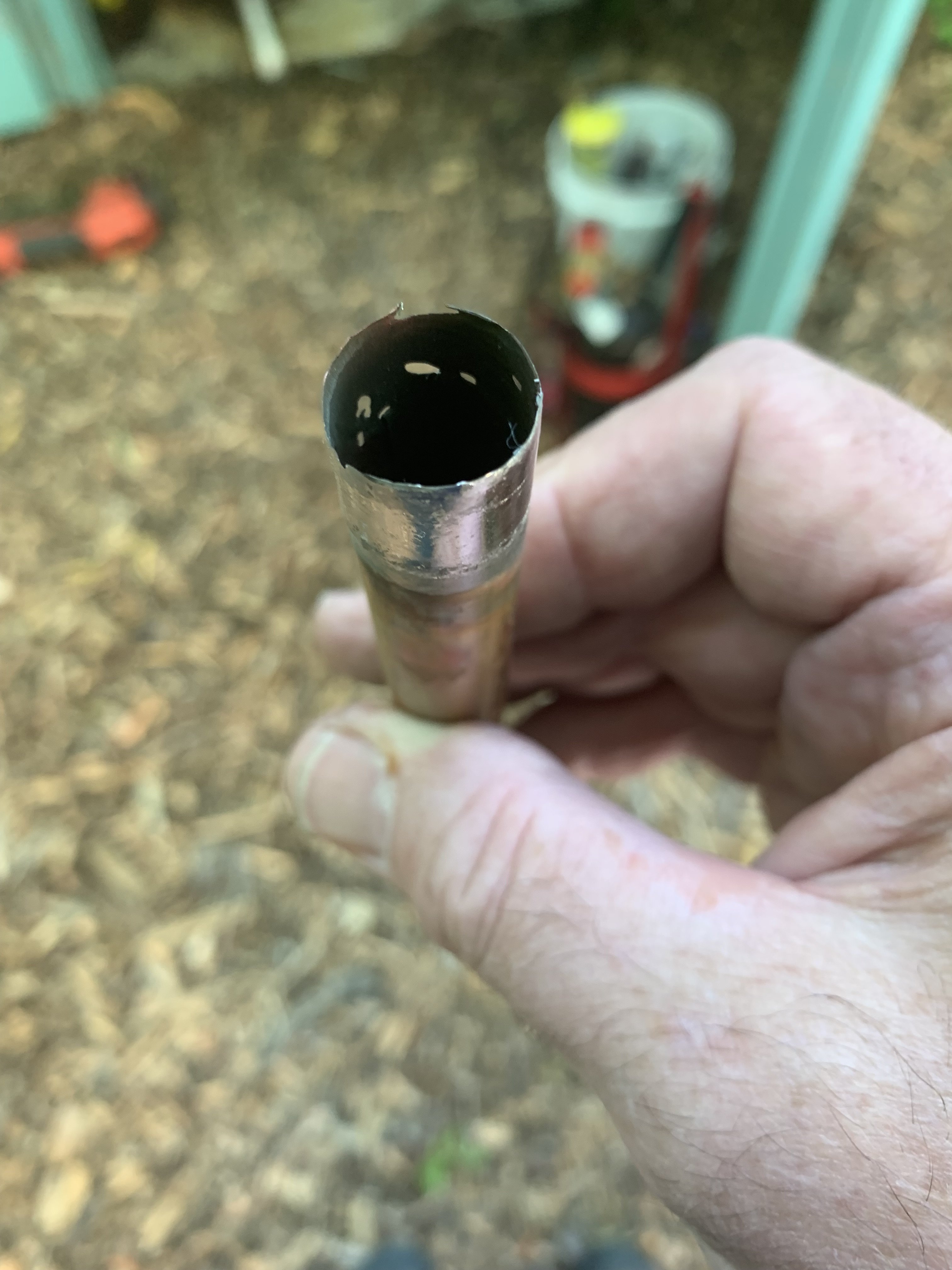
Thinning Copper

Two btu per sq ft for degree difference for a slab
Comments
-
I just saw this same thing yesterday , was told that the thinning copper was due to the amount of water passing that point .Also Found on the net " If the pipe ends weren't properly reamed smooth prior to soldering, the raised burrs inside the pipe can cause local turbulence, called erosion corrosion, which will corrode the pipe. " They told me to use Pex.1
-
I think that is erosion corrosion.
Beyond the obvious workmanship questions, reaming, over flux:ed.
A number of things can add up to cause that
velocity
turbulence
temperature
water quality
chemicals in the water from the supplierBob "hot rod" Rohr
trainer for Caleffi NA
Living the hydronic dream 2
2 -
-

This was soldered into a ball valve on a recir line.
The ball valve was throttled to reduce flow.
I think this was caused by the tumble of the water coming thru the partially closed valve.
This was a 40 bed 1971nursing home with plenty of copper installed.
This copper was maybe only 10 years old.
Non softened/treated water.
This is the only issue I have seen in the building over the last 40 years.1 -
Do you recall how far the valve was closed off? Cavitation caused by that restriction is another possibility.JUGHNE said:
This was soldered into a ball valve on a recir line.
The ball valve was throttled to reduce flow.
I think this was caused by the tumble of the water coming thru the partially closed valve.
This was a 40 bed 1971nursing home with plenty of copper installed.
This copper was maybe only 10 years old.
Non softened/treated water.
This is the only issue I have seen in the building over the last 40 years.Bob "hot rod" Rohr
trainer for Caleffi NA
Living the hydronic dream1 -
Not sure, typically the handle is half way, 45 degrees.
The threaded end might have screwed into a check valve.
It was some distance from the pump discharge.
Pump cycled on return temp.0 -
Definitely erosion-corrosion caused by too high a water flow velocity. The piping is literally wearing out from the inside. Too large a pump causing too large a water flow is the basic problem. Pinching a valve is a step in the right direction, but not adequate. A water flow velocity below 2 feet per second, is recommended.
CircuitSolvers™ by ThermOmegaTech are a brilliant and very simple product, that automatically and continuously regulates the water temperature and flow, 24 hours a day, 7 days a week. They providing a very simple, elegant, and inexpensive solution to a potentially very expensive water damage problem.
CircuitSolvers™ are installed on the return recirculation lines. We chose CircuitSolvers with a pre-set temperature of 115º F. This means the CircuitSolver valve is closed at 115º F and Open at 105º F – so our recirculation return runs about 110º F. Choosing the correct pre-set temperature setting is important.
Note - A similar problem occurs with PEX DHW Recirculation Systems for the same reason - too high a water velocity. I wrote a 24 page Mechanical Design Guide on DHW Recirculation Systems. Available to anyone that wants one.
Doug (E-Mail: gambas@shaw.ca)
1 -
Over-pumping a 3/4 copper line with this tiny circ? it will only do around 2 gpm. Well under 2 fps velocity? at the high end of the curve. With any piping at all it probably moving more like 1- 1.5 gpm.Doug_7 said:Definitely erosion-corrosion caused by too high a water flow velocity. The piping is literally wearing out from the inside. Too large a pump causing too large a water flow is the basic problem. Pinching a valve is a step in the right direction, but not adequate. A water flow velocity below 2 feet per second, is recommended.
CircuitSolvers™ by ThermOmegaTech are a brilliant and very simple product, that automatically and continuously regulates the water temperature and flow, 24 hours a day, 7 days a week. They providing a very simple, elegant, and inexpensive solution to a potentially very expensive water damage problem.
CircuitSolvers™ are installed on the return recirculation lines. We chose CircuitSolvers with a pre-set temperature of 115º F. This means the CircuitSolver valve is closed at 115º F and Open at 105º F – so our recirculation return runs about 110º F. Choosing the correct pre-set temperature setting is important.
Note - A similar problem occurs with PEX DHW Recirculation Systems for the same reason - too high a water velocity. I wrote a 24 page Mechanical Design Guide on DHW Recirculation Systems. Available to anyone that wants one.
Doug (E-Mail: gambas@shaw.ca)
What is the pressure drop thru the circuit solver, this pump may not even overcome that.
Something else going on this system. Could be in its past it had an oversized pump?Bob "hot rod" Rohr
trainer for Caleffi NA
Living the hydronic dream1 -
I am using a Grundfos 10-16 with Circuit Solvers and It works just fine in a 45,000 sq ft building. The Circuit Solvers maintain the correct temperature and prevent over-pumping. The flow is throttled back by the Circuit Solvers to about 1/4 of the flow that the Grundfos 10-16 pump would like.
The Grundfos 10-16 was not available until 2019 so it is clearly a replacement for a larger original pump, that did the damage to the piping.
Doug 1
1 -
1.Was this on a Standard 1/2" type "M" copper pipe ? (some assumptions are that it was 3/4" pipe)
2.Was a different circ soldered onto it in the past and was this"Erroded pipe" soldered directly onto the Grundfos vs the newer union type circs.
3.How old was this install and does the circ run all the time or is it controlled via a Timer/thermostat.
0 -
This is in a three-story 21 suite multi-family condo building with seven 2" DHW risers and seven 3/4" recirculation returns.
The original DHW Recirc pump was a UP 15-42 which pumped 10 GPM which is 6.6 ft / sec through the common sections of the 3/4" Type M copper recirculation return with no controls. This produced the "Thinning" of the copper tubing and pin-hole leaks wherever there was turbulence - such as poorly reamed tubing.
Twelve years ago we went to a UP-10-16 BN5 LC which pumps 2 GPM which is 1.3 ft / sec through the 3/4" recirculation return. We went a step further and added Circuit Solvers to each recirculation return.
Have not had a problem since.
The UP-10-16 recirculation pump runs all the time. The Circuit Solvers are 3/4" in-line self-actuating temperature controls which allow only enough flow to maintain the set temperature. The Circuit Solvers take pump sizing out of the equation. The UP-10-16 is doing less than 1.0 GPM.
See CircuitSolver at: https://circuitsolver.com
Doug
0 -
For dhw recirc pump sizing you need to know 2 things, heatloss of loop and pressure drop of the loop. Building size doesn’t necessarily have anything to do with the sizing
Gpm and head are the two numbers to size any circulator
A 100,000 square foot building could require a smaller circ than a 2000 sq ft building.
A thermal balance valve like the Caleffi Thermo setter or any other brand does not change the pump size.
Actually a delta p type recirc pump is the best as it modulates with the action of the thermal balance valve.
Some formulas and examples here
Bob "hot rod" Rohr
trainer for Caleffi NA
Living the hydronic dream0 -
Of course building size does not enter the DHW piping heat loss calculation. I only mentioned building size as part of the overall project description, to distinguish my example from a simple single-family house.
But DHW piping length and diameter do directly enter the piping heat loss calculation. In my example, the total DHW supply and return piping length is over 1,200 feet of different sizes - and this does directly enter the piping heat loss calculation which determines the pump sizing. A UP 10-16 pump is plenty big for this multi-family building with over 1,200 feet of insulated DHW supply and return piping.
It is the thermal balance valve like the CircuitSolver or the Caleffi Thermo setter that determines the flow, making pump size much less important - because it is the thermal balance valve that determines the flow. The thermal balance valve automatically provides the correct flow to maintain the pre-set temperature - no more and no less, and does this 24/7/365.
Insurers explain that water leaks are the largest source of insurance claims for multi-family buildings - larger that Fire and Theft combined. I know of one multi-family building that just spent $300,000 to re-pipe from Copper to PEX domestic water piping - without addressing water flow velocity. The maximum flow velocity for PEX is exactly the same as for Copper - 2 ft / sec. Out of the frying pan into the fire.
A little more thought put into into design of DHW recirculation systems and the use of thermal balance valves would avoid all this.
The attached shows the inner workings of the CircuitSolver.
Doug
0 -
Doug_7 said:
Definitely erosion-corrosion caused by too high a water flow velocity. The piping is literally wearing out from the inside. Too large a pump causing too large a water flow is the basic problem. Pinching a valve is a step in the right direction, but not adequate. A water flow velocity below 2 feet per second, is recommended.
CircuitSolvers™ by ThermOmegaTech are a brilliant and very simple product, that automatically and continuously regulates the water temperature and flow, 24 hours a day, 7 days a week. They providing a very simple, elegant, and inexpensive solution to a potentially very expensive water damage problem.
CircuitSolvers™ are installed on the return recirculation lines. We chose CircuitSolvers with a pre-set temperature of 115º F. This means the CircuitSolver valve is closed at 115º F and Open at 105º F – so our recirculation return runs about 110º F. Choosing the correct pre-set temperature setting is important.
Note - A similar problem occurs with PEX DHW Recirculation Systems for the same reason - too high a water velocity. I wrote a 24 page Mechanical Design Guide on DHW Recirculation Systems. Available to anyone that wants one.
Doug (E-Mail: gambas@shaw.ca)
Doug..I am confused about you Commenting with such detail on behalf of Alan's Post /situation.
Did you do a site visit/Consulting?0 -
Hi Derheatmeister - I only commented in such detail because I have seen the exact same situation - the exact same thinning of the copper, and the same pinholes in the copper DHW Recirculation piping, in my building. Sorry if this caused some confusion.
In my building the thinning and pinholes in the copper, which looked exactly like Alan's pictures, were caused by too high a water flow velocity in the copper DHW Recirculation piping, especially near the pump discharge, caused by too large a recirculation pump, which was replaced by a UP 10-16.
We also installed CircuitSolvers in each return branch. The CircuitSolvers guarantee minimum flows an in each return branch. Without these controls, water takes the path of least resistance with a higher than average velocity.
We haven't had a problem with thinning and pinholes in DHW recirculation lines since. I just wanted to share that experience. I have heard of lots of similar problems in multi-family apartments and condos. When the water leak is inside a wall on the 12 floor, you have a very expensive problem.
In Alan's case my first guess would be that the thinning and pinholes in the copper DHW Recirculation piping were caused by a previous larger pump. The UP 10-16 should be perfect with 3/4" or larger DHW Recirculation piping. If the UP 10-16 is the only pump that has been installed there, something else is going on.
Interestingly, Uponor requires that the water velocity in PEX recirculation piping shall not exceed 2 ft/sec. PEX is also subject to failure at higher flow velocities. See attached.
Doug
0 -
In DHW recirculating the velocity limitation has to do with hot chlorinated water, where water is constantly added
There is a time constraint also in pex recirculation, see the Rehau tech bulletin
Pex hydronic systems run up to 200F in some cases and 4 to 5 fps velocity is a common design number. Ive not seen a time constraint on pex used in radiant and hydronic?
More from UponorBob "hot rod" Rohr
trainer for Caleffi NA
Living the hydronic dream0 -
I Agree with the Chlorinated/high temp/Flow restrictions..
After my 2023 ISH visit we toured with Viega at the new training center "Viega World"..
They had a display on how to properly design domestic distribution/recirculating systems without allowing the formation of legionella yet conserving energy and water.
This display would go into a flushing cycle at which point every fixture was sanitised.
Image of display:
https://web-assets.viega.com/is/image/viegaprod/EX_ViegaWorld_Prevista_DE_2022_001-1?$700$
Viega also has a Special concentric fitting for domectic recirc lines (Pipe within pipe).
@Doug and Alan or anyone that is interested.
From the Viega World site.
Dr Christian Schauer is head of Viegas water expert team since 2016.
He a Doctor of chemistry with over 16 years of experience in drinking water hygiene, he spends his days working on practical, building-specific hygiene concepts that combine drinking water hygiene with energy efficiency. He acts as our in-house expert and also as a consultant for external parties.
Here is his Linkedin information https://www.linkedin.com/in/christian-dr-schauer-40014629/0 -
So maybe pex isn't all is is cracked up to be? Copper Ken was right!
")
Copper doesn't have a problem with UV, or continuous water temperature over 140F, or chlorine, or 4 fps, or mice. Copper flow is not restricted by the use of fittings, it can be left outside for years, centuries even.
Seems like more and more restrictions being placed on pex. And still failures after 40 years of pex evolution?
Allans thinning issue was probably a combination of issues, without knowing all the background. Velocity? Unreamed tube? Aggressive water?
There is no perfect piping product, one that can deal with excessive flow, chemicals, contaminants.
Maybe wooden pipes are going to be the long haul winner Or galvanized steel. Bob "hot rod" Rohr
trainer for Caleffi NA
Living the hydronic dream0 -

Agree... Copper is the "Better" in many ways.hot_rod said:So maybe pex isn't all is is cracked up to be? Copper Ken was right!
Copper doesn't have a problem with UV, or continuous water temperature over 140F, or chlorine, or 4 fps, or mice. Copper flow is not restricted by the use of fittings, it can be left outside for years, centuries even.
Seems like more and more restrictions being placed on pex. And still failures after 40 years of pex evolution?
Allans thinning issue was probably a combination of issues, without knowing all the background. Velocity? Unreamed tube? Aggressive water?
There is no perfect piping product, one that can deal with excessive flow, chemicals, contaminants.
Maybe wooden pipes are going to be the long haul winner Or galvanized steel.
just to name a few more.
It does'nt need to be flushed of cariogens as per State of California regulations.
With proper PH levels the "Grünspan" keeps it protected.
It is 100% recyclable and most likely will be worth more per pound in the future.
As you mentioned it can be subject to UV without problems.
One of the disadvantages is that it cost more to install.
For the masses that cannot afford expensive Copper installs in the future i predict a Layered combination of pex with Stainless or a cariogen free conduited pex system vs the wood or Galvanized steel") -1
-1 -
Watching some of the pex repipe lawsuits floating around, I'm not sure many of those homeowners would agree copper is more expensiveDerheatmeister said:
Agree... Copper is the "Better" in many ways.hot_rod said:So maybe pex isn't all is is cracked up to be? Copper Ken was right!
Copper doesn't have a problem with UV, or continuous water temperature over 140F, or chlorine, or 4 fps, or mice. Copper flow is not restricted by the use of fittings, it can be left outside for years, centuries even.
Seems like more and more restrictions being placed on pex. And still failures after 40 years of pex evolution?
Allans thinning issue was probably a combination of issues, without knowing all the background. Velocity? Unreamed tube? Aggressive water?
There is no perfect piping product, one that can deal with excessive flow, chemicals, contaminants.
Maybe wooden pipes are going to be the long haul winner Or galvanized steel.
just to name a few more.
It does'nt need to be flushed of cariogens as per State of California regulations.
With proper PH levels the "Grünspan" keeps it protected.
It is 100% recyclable and most likely will be worth more per pound in the future.
As you mentioned it can be subject to UV without problems.
One of the disadvantages is that it cost more to install.
For the masses that cannot afford expensive Copper installs in the future i predict a Layered combination of pex with Stainless or a cariogen free conduited pex system vs the wood or Galvanized steel
That repipe plumber in California is on his 4 brand of "top shelf" pex and still having failures?
Must be something in the air/ water in California that pin holes copper and breaks down PE tube? Wasn't California the last holdout to allow pex?
Imagine repiping a copper home and 5 years later the pex fails
While it is one mans opinion, Integrity Repipe has some interesting You Tube about multiple brands of tube failures.
The combination of temperature above 140, elevated chlorine or chloramines for "public health" and some areas requiring constant recirculation to protect seldom used section of the piping, makes for some interesting challenges.
Bob "hot rod" Rohr
trainer for Caleffi NA
Living the hydronic dream1 -
> It is 100% recyclable and most likely will be worth more per pound in the future.
Ahh yes, the copper piping retirement plan!!NJ Steam Homeowner.
See my sight glass boiler videos: https://bit.ly/3sZW1el 1
1 -
Alan - Suggest replacing that first section of Copper piping on the pump discharge with all Brass piping, and you should be good - see below.
The inside of the copper pipe is normally protected from corrosion by a thin copper-oxide layer. High water velocities can scrub away the protective layer from the inside of the pipe and you get localized corrosion, thinning and pinhole leaks. This corrosion occurs first in zones of high turbulence, such as the piping near the pump discharge, or near any un-reamed pipe ends.
This erosion-corrosion problem is unique to Copper DHW piping. Brass does not suffer from similar erosion-corrosion. Pump bodies which are subjected to very high turbulence are typically made of Brass.
The high turbulence inside the pump extends downstream on the discharge a little bit. If you sweat copper piping into the pump body, that copper will corrode rapidly. Today, the 10-16 is available in 3/4" brass union ends which solves that problem.
Design the entire DHW Recirculation piping system very carefully, to keep all the water flow velocities below 2 ft / sec in all branches, by installing CircuitSolver in each return branch to dynamically balance the system.
Switching DHW Recirculation piping to PEX does not solve this problem. You still have to keep the water flow velocities below 2 ft / sec in all branches. The best way to do this is still with a CircuitSolver in each return branch.
Doug
0 -
Thermal balance valves work by watching and responding the temperature where they are installed, typically at the return of the recirc branch(s)
Suppose you have a building with uninsulated HW piping, common in older buildings everywhere. Suppose also that piping runs through cold spaces, unconditioned space, 55° crawlspaces, basement plenum spaces etc. The thermal balance valve will open to whatever flow rate is required to try and meet the return temperature setting. It could require .5 gpm, or 4 gpm to get the return temperature required by the setter.
It does not, cannot maintain a specific flow rate or velocity. With a 5 psid the 3/4 valve you mentioned will allow 4 gpm, which is in excess of 2 fps in 3/4 copper tube.
Thermal balance valves offer a unique temperature solution for a temperature problem. Great for retrofitting older recirc installations with problems.
The recirc pump needs to be sized to provide adequate flow and pressure differential to overcome the most hydraulically remote, and or highest temperature drop circuit, if a building has multiple recic loops.
In some cases high head, high flow recirc pumps are needed to get the job done.
On large hotels, hospitals with sprawling pipe layouts we often see pumps pumps like Grundfos Magnas used. They provided the needed flow and also modulate with the thermal balance valve operation.
Keep in mind the pressure drop across the thermal setter needs to be in the calculation. When closed down expect a very low Cv. the ThermoSetter is .35Cv at the low end. The thermosetters need flow always to be able to respond, so the .35 needs to be accounted for in the pump calc. Another reason to use a delta P pump and let it run 24/7
In the example below the pump spec is 17.5' to get the 1.5 gpm in an insulated pipe example. Well beyond that 15-16 dhw pump.
The graphs below show the considerable heat loss difference between insulated and un-insulated copper. flow rate has to compensate for this. Typically you run a 10∆ on a recirc loop, leave the tank at 120, return from farthest fixture at 110°
A dynamic balance valve like a PIC valve would be able to limit the flow to a specific gpm, in a branch requirement. They too are used in DHW balance, but do not adjust or respond to temperature, Caleffi offers one with a temperature gauge for dynamic recirc balancing..
My point being you need to do some math when you install thermal type balance valves and spec the pump. The head required may surprise you.Bob "hot rod" Rohr
trainer for Caleffi NA
Living the hydronic dream 2
2 -
Hi Hot_Rod - Wow - a lot to unpack here.
In your example building with uninsulated DHW piping, a recirculation flow of 4 gpm is needed to get the required return temperature. This means the minimum piping size required to keep the flow velocity below 2 ft / sec would be 1" copper, not 3/4" copper. With 3/4" copper the flow velocity will be well above 2 ft / sec and you will suffer from erosion-corrosion causing thinning of the copper tubing and pin-hole leaks.
There are two-ways to solve this problem - one way would be to increase the recirculation piping size to 1" - or - you could insulate all the DHW piping to reduce the heat losses and the flow requirements.
We would choose to insulate the piping because of the large energy cost savings. Proper insulation greatly reduces the flow-requirements and the recirculation pump and piping sizes. Insulating DHW piping, with today's high energy costs, is a major cost-savings opportunity which will pay back year after year.
In your example the piping is insulated with 1/2" foam rubber, which reduces the piping heat losses to one-third of the un-insulated case. A good improvement.
Insulating the piping with 1" fibreglass will reduce the heat losses further - by almost 90%. Insulation allows you to stay below 2 ft / sec velocity with 3/4" tubing and to reduce the pump size significantly.
In the real case-study of our original multi-family building, the original DHW piping was not insulated. Big mistake, which caused high piping heat losses and required the recirculation flow to be too large. The common 3/4" recirculation piping had a flow velocity over 6 ft / sec. This caused serious erosion-corrosion of the copper piping, starting in areas of high turbulence. Same pictures as Alan and Total posted.
In our building we re-designed the DHW recirculation system to solve all of these problems. The first thing we did was insulate all the DHW supply and recirculation piping with 1" fibreglass, which reduces piping heat losses by almost 90%. The project to insulate our DHW piping saves us a lot of money every year on our heating costs. Basically you can't afford not to do it.
Insulating the DHW piping with 1" fibreglass reduced our recirculation flow requirement by almost 90% - which makes it a whole new ball-game. This allows the use of the tiny UP 10-16 pump. With CircuitSolvers balancing the flows in all seven branches, our total recirculation flow is only about 1.1 gpm and 3 feet of head at the pump.
Our UP 10-16 pump is operating at 3 feet of head. The head loss through the seven parallel recirculation returns is negligible. The only significant head loss is through the last few feet of common recirculation return piping, leading up to the recirculation pump suction. This is where the seven parallel 3/4" recirculation returns combine into one common 1" pipe leading to the pump suction. The pump discharge piping is also 1", but Brass rather than copper.
I agree that we need to do some math to correctly size the pump. Attached is the math we did in 2003 to calculate DHW Piping Heat Loss and required Recirculation Flow. Insulating the DHW Piping reduces the recirculation flow required from 10 gpm to 1.1 gpm, allowing the UP 10-16 pump to run in its sweet-spot in the middle of its pump curve.
Lots of room on the UP 10-16 pump curve for CircuitSolvers to balance the system to maintain the minimum required flow.
It is interesting to note that once all the piping is insulated, the pump head requirement of the pump become very low. Because Pump Head changes with the square of the Flow Rate, pump head drops like a stone as you reduce the flow rate below 2 ft / sec. Pump head becomes relatively un-important as a design parameter.
So a few things to calculate but many things to consider in providing a robust design.
Doug
0 -
In my town in Massachusetts I have seen countless examples of this in water piping. My family home, built in 1950 used 1/2" L copper throughout the whole house. Never saw a pinhole, even over 60 years later. Yet houses built in a development in my same town in the 1960's using L tubing showed signs of pinholing after 10 years or so.
That being said, I did find that our town water, which comes from well, was acidic. Carbonic acid which, which I was told, comes from the decaying of leaves. A natural acid, harmless to us, but raises hell with copper and brass, yellow brass inparticular.
I don't know as the quality of the copper in the 60's was different or whether the newer homes got water from different wells. But I am thinking acidic water may be the culprit0 -
In over 50 years I have observed this effect once. It was on the supply line of a dishwasher. Other than this type of failure by a joint, I have observed perforation (small corrosion holes) leaking in copper water lines and have been mystified as to what is causing it.
There is a new leak (corrosion) problem with Chinese black iron pipe. We own a number of steam systems so speak from experience. Very few people are aware of this problem but the enlightened few refuse to use it.0 -
I see a lot of this in the Manchester, NH area as a result of the municipal water supply and what I see as high levels of chlorination. There are other chemical, minerals and electrolysis which can contribute to this type of corrosion/erosion.
In the case presented, there are no signs of low pH, whereas no green (copper oxide) showing.
As mentioned above, velocity and cavitation can surely add to this.
Often times pumps on recirculation lines are too powerful. All that's needed is to move liquid slowly to keep the hot water where it's needed. Bigger isn't always better. Also consider the height of the upper most level for the correct pump needed.
All said, this keeps our trade in business.0 -
Piping and joining are inexhaustible subjects. I am surprised that soldered joints do not fail more often because it's so easy to do an improper job that will hold pressure initially.
There's also suspicions that there are bad batches of copper pipes/tubing. When those get into constant flow situations like recirc then decades later building owner will enjoy continuously new leaks.
I also new a contractor who would intentionally use wrong copper so that he'd get new business some years later.0 -
As mentioned in several posts, proper reaming is important. The Copper Development Association (CDA) recommends it. See quote below:
"If this rough, inside edge is not removed by reaming, erosion-corrosion may occur due to local turbulence and increased local flow velocity in the tube."
https://copper.org/applications/plumbing/cth/soldered-joints/cth_6soljts_ream.php
I do remember reading in one of Holohan's Hydronic books about air coming out of the solution (due to pressure changes) which can also cause corrosion from oxygen . Something to consider in addition to high velocity, chemistry of the fluid, etc.0 -
Hi mferrer - Good reference on proper reaming of copper pipe - very important. Good point on oxygen in the water causing corrosion.
Dissolved oxygen in the incoming domestic water is the source of the corrosion in copper DHW recirculation systems. Normally all copper piping quickly forms a thin protective copper-oxide film on the inside of the pipe, which very effectively protects it from further corrosion. When this protective film on the inside of the pipe is scrubbed away by high turbulence, the dissolved oxygen quickly reacts with the clean copper to create a new protective film. And so it goes - an endless cycle of erosion-corrosion until the copper pipe wears through.
We can't avoid the dissolved oxygen - so we have to limit the water flow velocity and avoid turbulence, to prevent erosion-corrosion of the copper in DHW recirculation systems You need to design the piping to keep the water flow velocities below 2 ft / sec. Reaming of copper pipe ends is very important to reduce local turbulence.
Doug0 -
I've seen it 100 times around Philly. USN electrical school; civilian HVAC&R and Oil and Gas burner training notwithstanding. Mostly worked larger commercial systems. (But see the problem mostly in [older] home-sized systems/buildings with some newer technology installed.) Spent nearly 20 years investigating property insurance claims cause-of-loss, and successfully argued many claims as an expert for both property owners and insurers.
The contributing factors vary, depending on the system, but the underlying problem is always the same. (One caveat is extremely acid (low pH below 5) water, or alkaline (high pH above 8) which would be a rarity, with untreated well water in a system. By all means however, if in doubt, check and rule out pH.
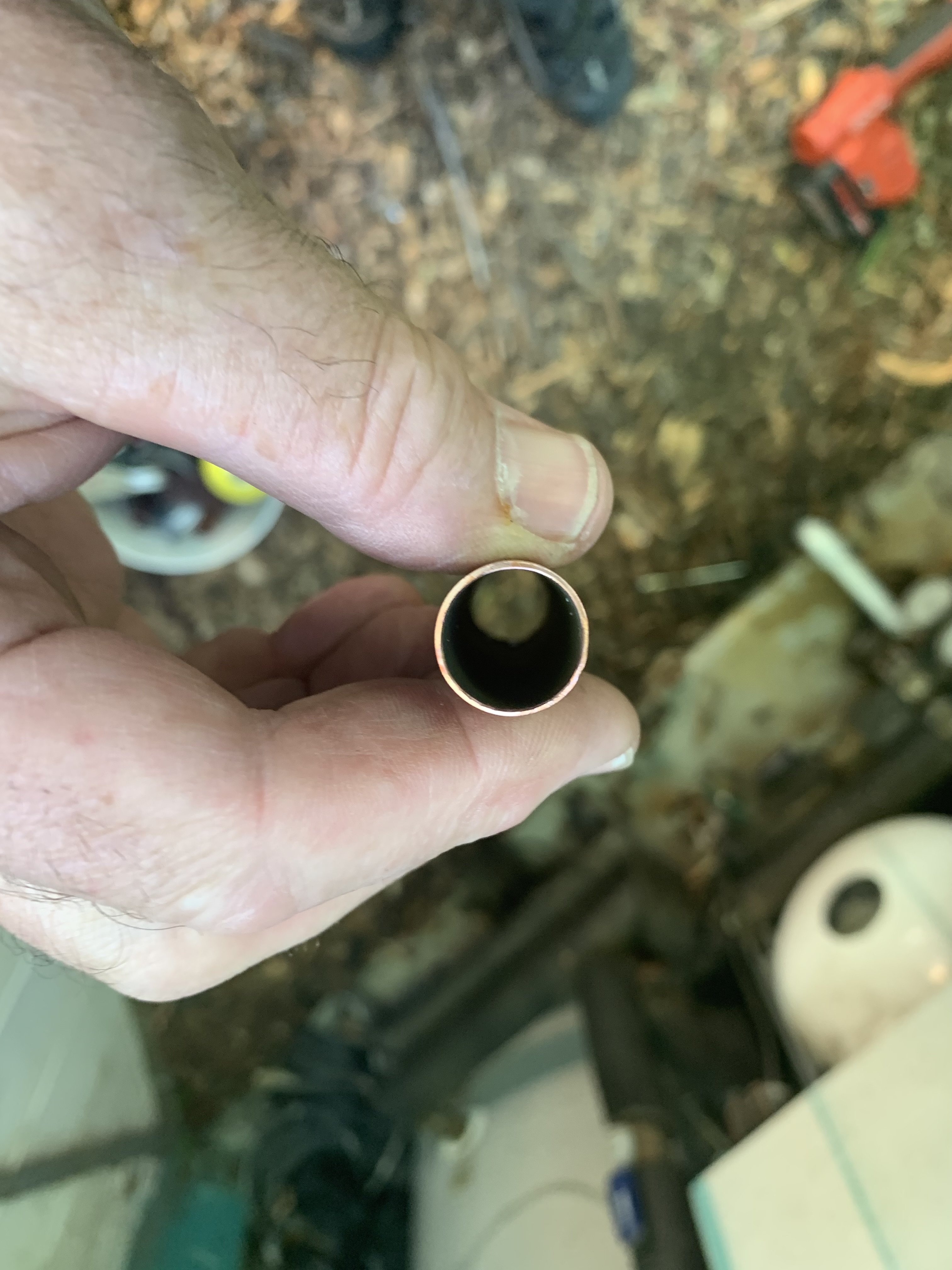
Here I want to interject, the second picture of the copper cut is not full or consistent wall thickness. That piece too has begun to thin, it's just hard to see. I will not explain all the scenarios here, or tell-tale signs, as they are many, and again, vary. I'd need Dan Hollahan to help me write a book.
Three main contributing factors most often cause this problem, and one common denominator has always accompanied, or can be the sole cause. IE: partial or full loss of earth ground. I was in NH at Viega with Lou Abruzzese formerly lead tech at United Refrigeration, to present technology to address this problem.
Problem, one word: ELECTROLYSIS. I would lie to forensically investigate your system and show you. (Moreover, the property owner may have insurance coverage for the damage.) Piecing-in plastic repair sections may aggravate the problem and send it elsewhere in the building. Significant damage or not, it will progress and/or re-emerge if not corrected, and it doesn't happen overnight. It is showing up so much because of newer technology such as VFDs and even ECMs. Pump Manufacturers deny a problem in fractional horsepower systems, but AEGIS RIngs were developed to address damage to multi-horsepower motors. I've witnessed and corrected it in systems with small variable speed circulators, and the problem even linked to variable speed combustion fans in gas boilers. It is a phenomenon engineering has touched on (as with AEGIS Rings) but not fully understood or embraced.
Do this: (and it can be quite tedious and detailed, or as simple as a new building electrical system earth grounding rod.) Check every ground connection in the building electrical system. At the very least, Ground Your System! as a stand alone. IE: drive a grounding rod next to your heating equipment if you must, ensure grounding including necessary shunts throughout and protect your system. Again, you may be sending the problem elsewhere in the building, but your stuff is protected.
This really needs a book written on the subject and real-life solutions/mitigation. Dan, help!
If I were there, I could demonstrate the effect and solution, but cannot address every system and every possibility here. This took me decades of empirical research in the field to fully grasp the depth and breadth of this insidious unseen, often slowly developing long term problem. I would love to inspect your Grundfos 10-16 ECM pump internals, some system components, and perform analysis on your copper piping.
Three examples: 1. Ever seen a hole pit right through the side of a water heater relief valve? 2. A law faucet at one sink rot down right in place? Same effect. In any case, you are basically electroplating the sewer, or something somewhere where transient currents can find ground. 3. Have inexplicable nuisance flame failures on that furnace you can't seem to solve? 99.9% you have a grounding problem.
Ground! Ground! Ground! Ground the World, so to speak. Then Ground some more.
This is me - Never developed the page:
https://www.facebook.com/DrGrounding1 -
ELECTROLYSIS: Grounding problems, somewhere. Telltale signs, guaranteed this is your problem.
Does the property owner have an insurance claim? How much damage has this done? Contact me at email on my profile page.0 -
I am guessing not reamed.
1 -
Tim - Good Guess - and a turbulent zone immediately downstream of the pump or a throttling valve.0


Categories
- All Categories
- 87.7K THE MAIN WALL
- 3.3K A-C, Heat Pumps & Refrigeration
- 59 Biomass
- 430 Carbon Monoxide Awareness
- 128 Chimneys & Flues
- 2.2K Domestic Hot Water
- 5.9K Gas Heating
- 121 Geothermal
- 170 Indoor-Air Quality
- 3.8K Oil Heating
- 79 Pipe Deterioration
- 1.1K Plumbing
- 6.6K Radiant Heating
- 396 Solar
- 16K Strictly Steam
- 3.5K Thermostats and Controls
- 56 Water Quality
- 51 Industry Classes
- 51 Job Opportunities
- 17 Recall Announcements