Welcome! Here are the website rules, as well as some tips for using this forum.
Need to contact us? Visit https://heatinghelp.com/contact-us/.
Click here to Find a Contractor in your area.
If our community has helped you, please consider making a contribution to support this website. Thanks!
Two-pipe to one-pipe conversion
Options
Comments
-
Okay, home from the Alps, back to reality.
I have found a tech I liked, and am thinking of, for the conversion to one-pipe (cut to chase: in addition to comments about the general setup, I’m interested in opinions re my leaning towards omitting the Tigerloop):
Firomatic (or ball-valve) at the above ground tank top inside the protective tub, so I have a shutoff outside the house. (I pictured a ball valve but these techs seem to prefer a Firomatic. It would basically serve as a manual shutoff out there though.)
I’m picturing jacketed copper line inside basement and out.
Into house at ground level through cinder block, down a few feet to an OSV, I’m thinking the SUNTEC PRV-38P which combines an OSV with a spin-on filter housing in one assembly, or just the PRV-38 if I can put it before the Firomatic (see next paragraph).
Another Firomatic just before the pump (or must it go before the filter? Could I do: OSV -> Firomatic-> filter so the OSV would cover any downstream leaks at Firomatic, filter or pump?)
I know many of you like Tigerloops, but I was inclining away from it. Part of the appeal to me of a one-line system is it reduces the extra hazard of the return line in case of a leak, plus much less volume is pumped through. The Tigerloop pumps two-pipe volume between it and the pump, and I’d rather not have that kind of volume anywhere in case of a leak. Plus my impression is that TL’s were originally mostly for tanks below burner level, my tank top is about 7 feet above the burner. And if the flares are good, I shouldn’t have a problem with air …?
As always, comments welcome.0 -
BTW, terminology: by OSV I mean an anti-siphon valve like the PRV-38, as opposed to the Firomatics, which are of course anti-fire. The occasional use of “OSV” to cover Firomatics confused me at first.Quick update: the SUNTEC PRV-38 manual says filter should go before valve, so that settles that. Probably will get PRV-38P which filters oil prior to it entering valve.
As for the Firomatic, I think it can go anywhere, but I imagine most of you put it before the filter so you can use it as a shutoff when you do anything with pump or filter, so I guess that’s the way to go. Can’t cover everything with the PRV!
So: Firomatic, anti-siphon valve with filter, pump.
Still interested in opinions re Tigerloop.0 -
How does this look?
 0
0 -
If the oil level in you tank is higher than the oil pump on the burner and if oil will get to the pump by gravity feed (not an overhead line) then a Tiger Loop is of no use.........unless you need it to warm up cold oil.0
-
Personally I try to reduce as many flare fitting as possible and usually use a 3/8 ips firematic in lieu of flare firematic valves . Personally I would not include a ball valve and would use a 3/8 flare x 3/8 ips fitting for the ips firematic and hard pipe to the spin on filter and to the inlet of the tiger loop and flex lines to the burner . On the pump pipe in and out from the bottom of the pumps body ,remember to install the by pass plug ,to make life easier 2 different length 1/4 nipples and 2 1/4 90s for a easy connection to the pumps inlet and outlet and this enables you to pull the pump screen cover off and not have to swing the tiger loop or filter housing around . I would also suggest to install a 1/4 black tee on the outlet of the filter prior to the tiger loop you can use the 1/4 plug out of the pump to plug it ,it’s a great place in the future to check to see if you have a restrict due to pulling high vacuum before the tiger loop .
Peace and good luck clammyR.A. Calmbacher L.L.C. HVAC
NJ Master HVAC Lic.
Mahwah, NJ
Specializing in steam and hydronic heating0 -
Thanks for the comments. @EBEBRATT-Ed I was hoping to do without a Tigerloop based on what you and @STEVEusaPA have said about them (my tank top is outside and 7 ft. or more above the burner) and because I don't like having even the short return line from the pump to the TL. But I really want to use the anti-siphon valve I got from Canada (which goes in right at the tank bushing) and they say a de-aerator must be used (hmm...).
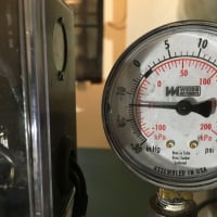
@clammy thanks, since I'm two-pipe now the plug is already in there, and I will do the different length nipples thing, great tip. I also really like your idea for a tee for a vacuum gauge; in the picture I have two filters, the sequence is: General filter-Firomatic-Tigerloop Ultra with spin-on filter attached, so should I put the tee on the supply line between the TL and the pump, so a gauge would measure the effect of both filters? You have solved a problem for me: I was hesitant to install an inline gauge because I heard they can blow, but the tee is a perfect idea (I do own a Westwood vacuum gauge I haven't used yet).
I wanted a ball valve for service shutoff because I've read enough stuff saying that Firomatics really shouldn't be used as manual shutoffs - my current one is leaking and sticks when I open or close it, and I feel like a ball valve of the same age wouldn't leak. But I will think about how I can minimize flares, and will hard pipe between filters and Firomatic.
I was planning to use 3/8 copper tube instead of flex lines between TL and pump, but @STEVEusaPA has even suggested hard pipe. If he hops on here and convinces me why that'd be better than 3/8 tube, I might do it.0 -
When done w the flex lines there no excuse for removing the pump to check blower ,burner coupling and seal on pump it also has to be able to move if you’re going to open the combustion chamber . When piped in copper or hard pipe it’s more work to get the pump out of the way to either remove the burner plate or swing door and open the combustion chamber to vacuum out and brush out plus in some cases you have to undo flares and remove the lines from the pump it ends up creating a mess and possible creating leaks when everything is re assembled just makes yearly maintenance a bit more then it should be . The osv is a great addition and personally I ve had a call where the pump seal went and was siphoning fuel out of the in ground tank which was at a higher elevation of course some ancient j or h pump great memories of oil service late at night and digging through the service van for a viable replacement 1750 rpm pump if I remember correctly what a terrible late nite call a real mess . I really don’t think you should need anything more then the spin on unless you have an old tank and possibly water getting in . Also as other have found by experience on the ultras w the spin on and vacuum gauge the fine thread fitting for the 1/8 vacuum gauge is some times prone to leakage either by pulling air and or leaving a fine oil film so advice is use leak lock on the threads and don’t over tighten it and leave the flat head service valve to the gauge off unless checking the vacuum .just a little heads up
Peace and good luck clammyR.A. Calmbacher L.L.C. HVAC
NJ Master HVAC Lic.
Mahwah, NJ
Specializing in steam and hydronic heating0 -
Yeah, I’ll have to make that choice about the flex lines.
And maybe I’ll try going with just the spin on and see how that goes. Fewer fittings, and it seems like it’d be no big deal to add the wool filter later if I wanted to.
As for the gauge, based on what I think you were suggesting before I thought I’d get a 1/4x1/4x1/4 brass tee (all FIPs) and put it on the supply line between TL and pump and then put in a plug so checking vacuum would be easy. I could just remove the plug and screw in a vac. gauge which I see go for less than $10. (So why did I spend & $60+ on a Westwood t15 Vacuum Suction Line Analyzer - basically a gauge with a tube and a couple of adapters? Oh the mysteries of life.)0 -
Well @pecmsg you sure were right about that, see photo.pecmsg said:That’s why the return only goes in to the top of the tank well above the oil level.Your guy wants to install valves that are not allowed how do we know he followed that rule as well?
BTW, any tips for getting a stuck bushing off (I’m using a different one)? See photo. Can’t get leverage with pipe wrench and pipe over handle, sprayed PB Blaster. Thought of two nipples in the holes or the old fittings to get leverage or stick a monster screwdriver or something between, but I’m afraid of screwing up the threads where plugs would go - it would not be good if I could neither get this thing out nor put in plugs.
Not essential though cuz the 2” plug on the other side comes out, it would just be a longer run to the other side of the tank and down to house.


0


Categories
- All Categories
- 87.7K THE MAIN WALL
- 3.3K A-C, Heat Pumps & Refrigeration
- 59 Biomass
- 431 Carbon Monoxide Awareness
- 127 Chimneys & Flues
- 2.2K Domestic Hot Water
- 5.9K Gas Heating
- 121 Geothermal
- 170 Indoor-Air Quality
- 3.8K Oil Heating
- 79 Pipe Deterioration
- 1K Plumbing
- 6.6K Radiant Heating
- 396 Solar
- 16K Strictly Steam
- 3.5K Thermostats and Controls
- 56 Water Quality
- 51 Industry Classes
- 51 Job Opportunities
- 17 Recall Announcements