Erosion of copper coax heat exchanger-ClimateMaster GSHP

Heat exchanger was removed and returned to ClimateMaster for analysis. Report came back saying failure was due to pin holes and thinning of heat exchanger walls, most likely due to erosion.
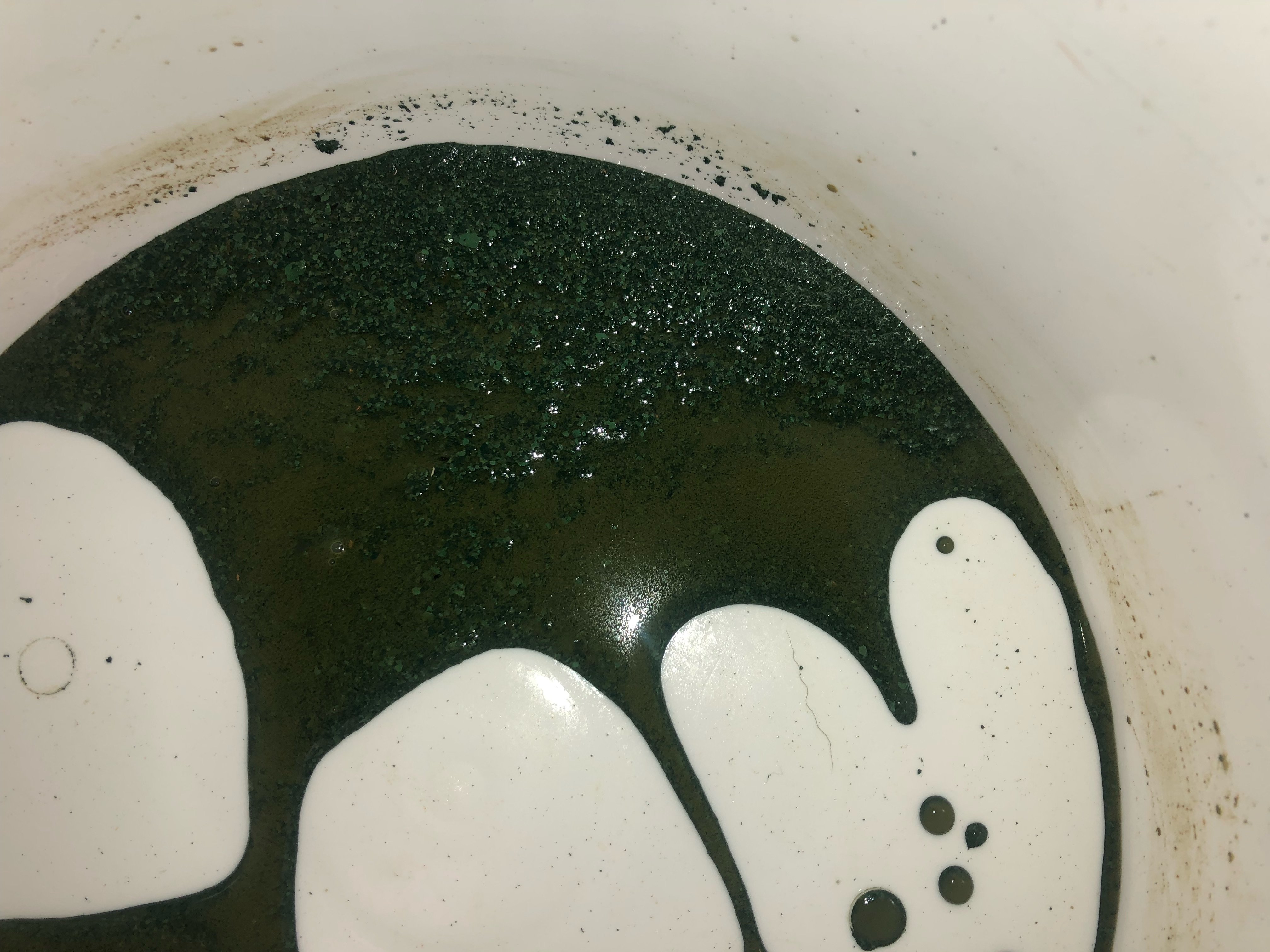
I then purged the loop field of all contents. Fluid contained no contaminants or debris except for refrigerant oil and a turquoise color material resembling the texture of ground coffee, which I believe to be copper from the heat exchanger.
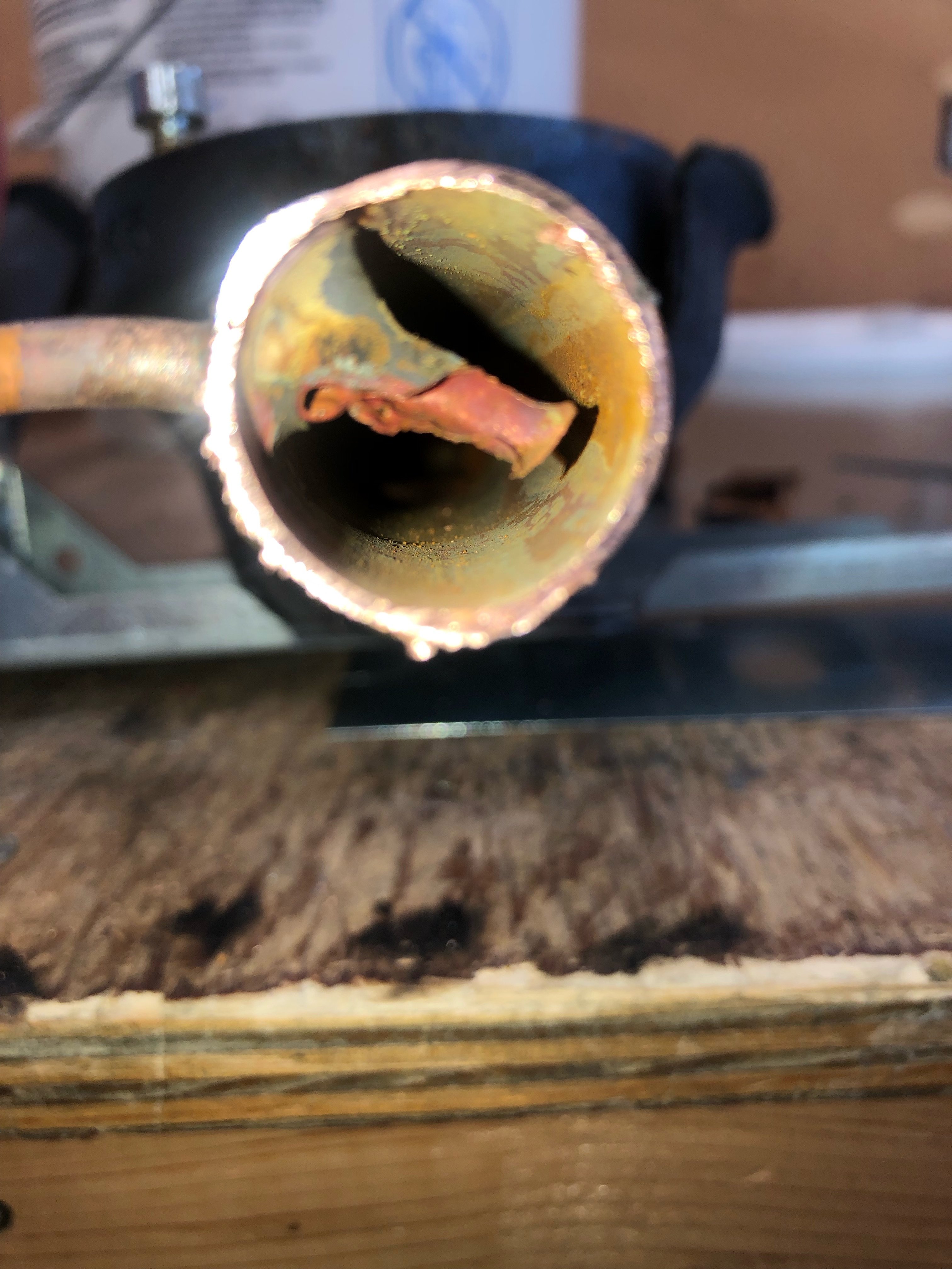
At this point I could see nothing causing this erosion. Then I started to remove the internal circulator and some piping from the unit and found something interesting. A 1/4" copper tube was brazed into the copper tubing on the inlet side of the ground loop circulator for pressure drop measurement, this tube had been extended incorrectly into the flow path and has been eroded. The erososion of the heat exchanger looks to have started when copper material was introduced into the fluid and then started scraping the walls of the heat exchanger and piping, the problem compounding as more eroding takes place.
The cast iron circulator housing looked to be in good shape, no erosion or corrosion.
The ground loop flow through the 3/4" copper tube is 12 GPM/8 FPS. Ground loop constists of HDPE and 48" of rubber hose near unit. Closed loop/ Horizontal Heat Exchanger
Fill water/methanol was tested and within installation manual parameters
This looks obvious to me this all started with the 1/4" tube being installed incorrectly at the factory. ClimateMaster has said this is not possible.
Any Thoughts?

Comments
-
Hello, Isn't flow for copper supposed to be around four feet per second max? I know it can take higher flow for a short duration, but not long term. Can the flow be reduced and the system still work?
Yours, Larry 2
2 -
The system design system flow is 12 GPM this equates to 8 ft per second going through piping. Just a note this is the internal piping of the heat pump unit.
It is my understanding that under normal conditions this is tolerable if designed for, but when an obstacle is placed in the flow path, velocity and turbulence is increased causing erosion.
The 4ft per second rule would not apply to this piece of equipment.
0 -
The turbulence caused by that probe might have caused some erosion in its immediate vicinity, but only if there were particulates already in the fluid or the pressure was low enough to cause cavitation (highly unlikey). You may be looking at a chemical erosion problem, rather than a mechanical one. They can look very similar.Br. Jamie, osb
Building superintendent/caretaker, 7200 sq. ft. historic house museum with dependencies in New England0 -


See Siggy's comments on erosion corrosion.0 -
Jamie,
All fluid was removed and there were no contaminants found except for copper from erosion. I rule this out being chemical because if it was the other metal components in this system would be affected, the cast iron circulator housing for example. The circulator impeller and volute have no damage.0 -
what is the ph of the fluid?
metal attack could be aggressive fluid, electrolysis or excessive flow
cavitation also erodes pipe and could be caused by an obstruction and high flow velocity. Usually you will hear some noise at the point of cavitation, a crackling sound as the vapor pockets collapse. This in turn causes a very aggressive erosion of metals. Bronze pump impellers can cavitate to shards in a weeks time!
Unreamed copper tube can also cause erosion pinholes
12 gpm is too high IMO for 3/4 copper tube, as is the resultant 8 fps
A 20’ diameter overflow tube at the Glen Canyon dam wore through from a cavitation incident caused by a tough surface inside that concrete tube, back in the 1980s
We’re talking tens of thousands cubic feet per second of flow!
Bob "hot rod" Rohr
trainer for Caleffi NA
Living the hydronic dream0 -
Chemical corrosion will affect different metals differently. Cast iron being rather insusceptible, while copper is notoriously susceptible. Worse -- mixing cast iron and copper can accelerate corrosion of the copper in some situaitioons.bnjmn said:Jamie,
All fluid was removed and there were no contaminants found except for copper from erosion. I rule this out being chemical because if it was the other metal components in this system would be affected, the cast iron circulator housing for example. The circulator impeller and volute have no damage.Br. Jamie, osb
Building superintendent/caretaker, 7200 sq. ft. historic house museum with dependencies in New England0 -
If it is a closed, tight, sealed system with no oxygen ingress, the GEO fluid with inhibitors should protect all the metals
If the GEO fluid was mixed on the site with hard or high TDS water, that can compromise the fluid. But a fluid analysis would indicate that?
You could have a combination of all these possibilities
It may be good to run a cleaner through the system when you refill, at least the components in the mechanical room, to get back to a clean system. Then pump in a good brand, premixed GEO fluid.
But that flow velocity is not ideal, any way to repipe some?Bob "hot rod" Rohr
trainer for Caleffi NA
Living the hydronic dream0 -
System was initially filled using 50/50 Econar Geothermal Transfer Fluid and water from a tested source with a pH of 8.06
The flow rate and velocity going through the heat pump is not possible to change.
The ground loop will be cleaned and flushed before being put into service with the new heat pump. With the refrigerant and oil being mixed with ground loop fluid it's a mess.
It is a sealed tight system, consisting of only HDPE. System was filled and flushed using a pressurized, reversable flow and filtered (5"x36" 100-micron filter) purge cart. System has maintained 50-70 PSI loop pressure since installation.
I believe the heat exchanger failure was caused by copper particles being eroded from the 1/4" tube restriction area. These eroded particles then became the abrasive agent in the system fluid and damaged other parts of the system mainly the copper coax heat exchanger. The channels in the heat exchanger induce turbulent swirling flow so erosion in these areas will be accelerated.
0 -
Sounds very fustrating ...I get the eroded particle downward spirol.bnjmn said:System was initially filled using 50/50 Econar Geothermal Transfer Fluid and water from a tested source with a pH of 8.06
The flow rate and velocity going through the heat pump is not possible to change.
The ground loop will be cleaned and flushed before being put into service with the new heat pump. With the refrigerant and oil being mixed with ground loop fluid it's a mess.
It is a sealed tight system, consisting of only HDPE. System was filled and flushed using a pressurized, reversable flow and filtered (5"x36" 100-micron filter) purge cart. System has maintained 50-70 PSI loop pressure since installation.
I believe the heat exchanger failure was caused by copper particles being eroded from the 1/4" tube restriction area. These eroded particles then became the abrasive agent in the system fluid and damaged other parts of the system mainly the copper coax heat exchanger. The channels in the heat exchanger induce turbulent swirling flow so erosion in these areas will be accelerated.
As others have mentioned
1. Why the higher flow rates?
2. Why was the 1/4" Reference tube extened so far into the pipe ?
3. Does the HDPE have a O2 barrier?
4. Does the Rubber hose have a O2 barrier?
4. What are recommended flow rates from the manufacturer?
1 -
The flow rate is the designed ground loop flow rate for this heat pump, determined by manufacturer.The 1/4” tube extending into the flow path was a mistake by the factory.
All materials used are industry standard and meet or exceed IGSHPA guidelines. No 02 problems.0 -
I doubt very much that that misaligned probe was the source of the problem -- which means it will likely return, unless you figure out what really was the problem.Br. Jamie, osb
Building superintendent/caretaker, 7200 sq. ft. historic house museum with dependencies in New England0 -
The “misalignment” of the probe is a manufacturing defect. It is supposed to be go in just far enough for a strong joint and smooth flow path.0
-
GEO tube is not usually oxygen barrier. The temperatures that it operates at are not as big a concern for 02 ingressI have seen pics of severely corroded iron body circulators on GEO sites and at wholesalers. I always suspect the fluid, as its rare to see a fill system on GEO
Grundfos did have have a resin coated cast iron body pump for GEO. Maybe they still do, or push installers to stainless circs. So the industry is aware if corrosion issues.
I dont know what inhibitors are added to the methanol or ethanol fluids? As with glycols, the price per gallon often has to do with the quality and quantity of inhibitor package.Bob "hot rod" Rohr
trainer for Caleffi NA
Living the hydronic dream 1
1 -
Aye. Whiile lawyers just love manufacturing defects, unfortunately people who actually need things to work often don't care -- particularly ones like this one.bnjmn said:The “misalignment” of the probe is a manufacturing defect. It is supposed to be go in just far enough for a strong joint and smooth flow path.
Br. Jamie, osb
Building superintendent/caretaker, 7200 sq. ft. historic house museum with dependencies in New England0 -
Is that flow rate a measure value, the 12 gpm? Is it possible it could be much higher?
Typically 3 gpm per ton, what size is this system?
No question that was a botched insertion of that 1/4" tube, I agree it had some effect on the deterioration.
How to prove it is a tougher question.
We have had electronic ball valves returned that were grossly oversized. This forced to ball to operate while only 10%, or less, open. It does in fact erode that brass ball, and quickly! Within 1 years time it ground the ball to just a chunk of brass that was unrecognizable.
I've been flow testing a probe inserted into a 3/4 tube at high flow velocity, although it needs to be a long term flow test you can hear, actually feel the vibration at the restriction. It is a short section of 3/4, I can pump over 20 gpm through it. The sight glass allow me to see any air of vapor pockets forming.
A couple things that encourage cavitation are high temperature, but also low pressure. The section of tube just downstream of the obstruction would be where to look for erosion.
Does the system have an expansion tank? It should. It also needs to be overcharged so pressure can be positive as the fluid cools.
Bob "hot rod" Rohr
trainer for Caleffi NA
Living the hydronic dream2 -
Bob..I like that you have again gone the extra step with the Experiment/Instrumentation.hot_rod said:Is that flow rate a measure value, the 12 gpm? Is it possible it could be much higher?
Typically 3 gpm per ton, what size is this system?
No question that was a botched insertion of that 1/4" tube, I agree it had some effect on the deterioration.
How to prove it is a tougher question.
We have had electronic ball valves returned that were grossly oversized. This forced to ball to operate while only 10%, or less, open. It does in fact erode that brass ball, and quickly! Within 1 years time it ground the ball to just a chunk of brass that was unrecognizable.
I've been flow testing a probe inserted into a 3/4 tube at high flow velocity, although it needs to be a long term flow test you can hear, actually feel the vibration at the restriction. It is a short section of 3/4, I can pump over 20 gpm through it. The sight glass allow me to see any air of vapor pockets forming.
A couple things that encourage cavitation are high temperature, but also low pressure. The section of tube just downstream of the obstruction would be where to look for erosion.
Does the system have an expansion tank? It should. It also needs to be overcharged so pressure can be positive as the fluid cools.") Thats awesome !!
Thats awesome !!
One question..Would a brass probe insert port withstand the high velocity better than a 1/4 " Copper tube ?0 -
We started plating the brass well to see if that helps. These are mostly used on potable water mixing valves
same challenge trying to determine if it is velocity, certain water chemicals being used, high mineral content in the water, maybe all 3?
Ive seen wells in indirect tanks and boilers fail also, and have never pinpointed the cause. The metal is often blamed, or thickness and quality of the wells?
Maybe stainless, monel, or unobtanium is an option. All metals have weakness. Chlorides go after stainless tanks and boilers. Aluminum boilers are ph sensitiveBob "hot rod" Rohr
trainer for Caleffi NA
Living the hydronic dream1 -
Just thinking from a different perspective, was the freeze protection rating of the initial fill tested? I’m trying to imagine the effect of repeated freeze thaw cycles on the tubing. I know it shouldn’t be an issue at 50/50 but if the original fluid wasn’t to spec then maybe it could be?0
-
8 GPM for how many tons?
0 -
Hopefully not freezing near the copper...Out in the field is a different storyMatt_67 said:Just thinking from a different perspective, was the freeze protection rating of the initial fill tested? I’m trying to imagine the effect of repeated freeze thaw cycles on the tubing. I know it shouldn’t be an issue at 50/50 but if the original fluid wasn’t to spec then maybe it could be?
0 -
This is a 4 Ton water to air unit.
Methanol concentration is 25%Loop field circulation is done with an internal Grundfos variable speed circulator (modulated water flow). Internal expansion tank as well. Unit has never seen an entering water temp below 35 F.
Here is a pic from a 5 Ton Climate Master water to water heat pump. This heat pumped was replaced by Climate Master because
of a refrigerant circuit problem. I scraped the unit but still have the water loop fittings from the unit. This is after 2 years of operation. 15 GPM 1” copper. I would be ashamed to send work out that looks like this. 0
0 -
I imagine those were straight cut copper nipples, so erosions has worn them jagged
when you do a T Drill joint there are two dimples on the stub to indicate protrusion depth. Per code the second dimple needs to be visible to an inspector. This indicates the nipple is in the correct position and not sticking into the pipe run,Bob "hot rod" Rohr
trainer for Caleffi NA
Living the hydronic dream 1
1 -
We have a T Drill and the material for the Intersection/Branch is pulled outward (In the opposite direction as the pictures shown) .. Not sure how they made this connection, It looks like they used a punch and then inserted the branch which IMO is the wrong way.. Still think that the flow rates are elevated for this size pipe..hot_rod said:I imagine those were straight cut copper nipples, so erosions has worn them jagged
when you do a T Drill joint there are two dimples on the stub to indicate protrusion depth. Per code the second dimple needs to be visible to an inspector. This indicates the nipple is in the correct position and not sticking into the pipe run,
 2
2 -
Regardless of all that, that is some horrific fabrication in the OP picture.
"that pipe is too big, let's make this more sporty"
0 -
The MFG should be in his pocket for at least some of this.
12 gpm for 3/4" is 3x what it should be and their shoddy workmanship is a whole nother issue. You put that much flow through 3/4" you eventually going to have problems even if the water quality and chemistry is perfect.
0


Categories
- All Categories
- 87.7K THE MAIN WALL
- 3.3K A-C, Heat Pumps & Refrigeration
- 59 Biomass
- 430 Carbon Monoxide Awareness
- 129 Chimneys & Flues
- 2.2K Domestic Hot Water
- 5.9K Gas Heating
- 122 Geothermal
- 170 Indoor-Air Quality
- 3.8K Oil Heating
- 79 Pipe Deterioration
- 1.1K Plumbing
- 6.6K Radiant Heating
- 396 Solar
- 16K Strictly Steam
- 3.5K Thermostats and Controls
- 56 Water Quality
- 51 Industry Classes
- 51 Job Opportunities
- 17 Recall Announcements