Zone that doesn't heat properly
Comments
-
Go ahead, and leave it for now, and do your readings.
I'm pointing out some obvious things. Changes, and comparisons old to the new.
0 -
Again these are the three scenarios.
Your scenario matches boiler flow is greater than system flow.
Keep in mind the images are just for reference. There is mixing in the boiler flow being greater than system flow. The system flow is tempered down by the return temp.How much you would need to plug in the numbers to the formula.


Remember what goes into a t must come out of a t on both sides of the hydraulic separator.
0 -
EDIT (Gordy posted some diagrams that make this post redundant). If the boiler flow is high than you should have the third diagram occuring where the System and Boiler Outlet are equal. Perhaps the system sensor isn't that accurate.
If the boiler flow (primary) was higher (or equal) to the system flow, than the system supply temp should be pretty much the same as the boiler outlet temp (diagrams 1 or 3), but it's not.
The system supply temp (secondary SWT) is substantially lower than the boiler outlet, which means some cold return water got mixed in somehow (see diagram 2 above). Usually that means the secondary flow is exceeding the primary flow.
The high pump speed I suggested was just an experiment to see if it moved the needle in the right or wrong direction.
I agree with Gordy that the primary pump appears to be moving too much water.
You can throttle a ball valve a bit if speed 1 is still too much flow.
It would be good to get an outdoor reset going once you've got your issues sorted out. 165degF shouldn't be necessary most of the time.0 -
Depending on the differences in flow there is always some mixing going out to the system, and coming back. The only scenario with a definite out come is equal flow rates on both sides. Other than that there is always some mixing. How much depends on flow differences, and temps.
When you have a bunch of different zones that go on, and off in different combinations with different flow rates, emitters, and loads things are not so cut, and dry.
0 -
If you look at the illustrations in my post where flows are not equal. Greater flow on boiler side favors that side of the separator. When flow is greater on the system side it favors that side of the separator. As flows become closer together the mixing starts to drift towards the center of the separator.
When flows are equal that mixing breaks, and goes directly to the adjacent port.0 -
Just to back up, is there still an ongoing comfort problem, or is it purely system optimization now?0
-
I flushed out the trap on the separator and ran a 8" wire up in it and worked it around. I got quite a bit more crud out of it and still get a little black sand looking stuff when I flush. Also I get an initial burst and then it trails off to a steady stream.
Boiler firing at 100% primary pump on "LOW"
inlet temp 160
outlet temp 182
delta T 22
flue temp 197
Secondary supply 149
return 117
outside 22 degrees and sunny0 -
I wouldn't go that far with the throttling. But if the fire rate is high and the Delta less than 20degf then it would be worth throttling a bit. Do a little than run it for hours or days before changing it again.
It sounds like perhaps your system could use a good flush. Maybe a summer project.0 -
When tracking system side temps are you noting how many zones are calling and which ones?0
-
OK, I'll try that... this past fall I had my local heating tech flush out the antifreeze and refill with water and cleaner, after 2 weeks flushed out the cleaner/water and refilled with water and a "conditioner". Do you think I should do this process again? I must admit the water that has come out of the system when I changed pumps was NOT clean looking water. In fact it looked kind of muddy.SuperJ said:I wouldn't go that far with the throttling. But if the fire rate is high and the Delta less than 20degf then it would be worth throttling a bit. Do a little than run it for hours or days before changing it again.
It sounds like perhaps your system could use a good flush. Maybe a summer project.0 -
Thanks for the pics, I was really confused on the piping coming out of the hydraulic separator. I got it now.Tom
Montpelier Vt0 -
After studying your attachments, it seems I need to put one of these [B&G 117413 - CB 3/4" Sweat Bronze Circuit Setter & Balancing Valve] in each zone in order to measure and control flow through the emitters. I figure this may be necessary as my zones are very different in size and type of emitter. What do you think?hot_rod said:The purpose of balancing is to assure each zone or loop gets adequate flow, but not excessive to the point of causing noise, wear, etc.
"A properly balanced system is one that consistently delivers the proper rate of heat transfer to each space served by the system"
Just to be clear, the faster fluid runs thru any heat emitter, the higher the output. This is because the AWT thru the heat emitter is higher. It's not about the ability of BTUs being able to jump on or off.
These attachments better explain the math and show, in color, the difference in output between a low ∆, low flow and a high ∆ high flow circuit, same SWT in this radiant loop drawing. Same applies to any heat emitter or exchanger.0 -
OK Jamie, this has been a confused situation as far as I have noticed. No one seems to sell a "back flow preventer" which by literal description would be the same thing as a check valve. What exactly is the difference and why would one be used instead of the other?Jamie Hall said:Department of minor thoughts -- if that "back flow preventer" is as you describe -- a simple flap -- that is not a backflow preventer. That's a check valve. Very different critter.
As far a I can see a "check valve" , or at least the one that comes with a new grundfos pump, obstructs flow by somewhere around 50% of a 3/4" pipe's flow capability. I am planning to take all these "check valves" out of my pumps and install the flap type check valve/back flow preventer or whatever, and install a "flap type" valve, which doesn't obstruct flow at all, in the return of all my zones. That way if I need to slow down a zone's flow, I can do it with a ball valve where I at least have control over how much "obstruction" is in the pipe. . . . . Your thoughts?0 -
You have a bit going on from the original setup.
When you had all zone valves you did not have to worry about gravity flow. You changed everything to pumps, and added two more zones with pumps.
You did not have a hydraulic separator before, and now you do.
Everything worked fine before, and now there is problems.
First goal in trouble shooting is identifying what changed, and go from there.
I’m still not comfortable how the separator is responding to the primary flow changes with the primary pump. Assuming there was no fiddling with anything on the system side when changes are made.
The primary side is acting as it should. You gained a delta , and have a higher supply temp by slowing down the pump, but lost system supply temp........
182 out of boiler
160 return to boiler
149 system supply sensor to boiler
117 return from system
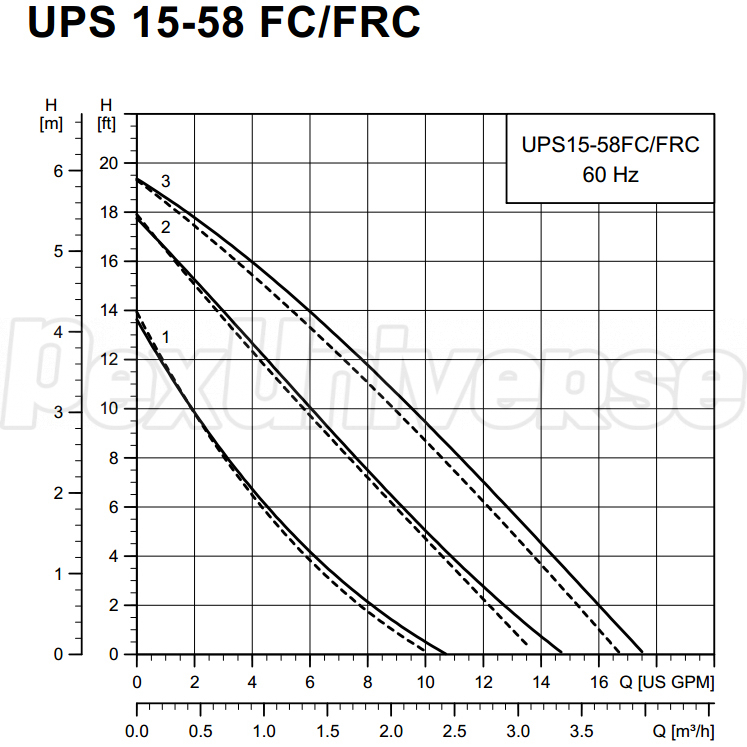
In theory according to the manual the boiler flow is 9.8 gpm with a 20 delta at 100% modulation. With a 22 delta you are slightly less.
This tells me the boiler is still flowing faster than the system side. What we don’t know is how many zones are running when these measurements were taken.
And that the system side is flowing much less than the boiler side, because of your high boiler return temps.
0 -
Gordy: I'm a little confused here.. I have slowed zone 3 down to the lowest setting on the alpha2 and throttled it down a little more with a valve to 2 gal/min. If we are concerned that the system flow is slower than the primary side, why did we do that? As I remember, we were trying to get the delta for the zone up higher.0
-
A simple check valve does prevent backflow, but is not what thought of as a backflow preventer for plumbing -- or code -- purposes. Some codes do permit a double check valve as a backflow preventer -- simply two check valves in series in the same assembly. Some codes -- and authorities -- do not. Instead, they are looking for a device which has a check valve, then a chamber which has a slightly lower pressure than the supply side, then another check valve. The intermediate chamber is valved in such a way that if it's pressure should rise to approach the supply side, or drop below the downstream side, it is vented to atmosphere instead.ntonkin said:
OK Jamie, this has been a confused situation as far as I have noticed. No one seems to sell a "back flow preventer" which by literal description would be the same thing as a check valve. What exactly is the difference and why would one be used instead of the other?Jamie Hall said:Department of minor thoughts -- if that "back flow preventer" is as you describe -- a simple flap -- that is not a backflow preventer. That's a check valve. Very different critter.
...?
If it has test valves on it, it is referred to as a backflow preventer assembly; otherwise it is a backflow preventer device.
It requires three distinct, unrelated, simultaneous failures to occur before there is a possibility of backflow, whereas a check valve only requires one; a double check valve requires two, but they are regarded as related. They are used whenever there is a possibility of a significant hazard to drinking water quality on the downstream side. Some of these hazards are pretty obvious -- such as glycol or other chemicals in a boiler. Others, such as the acids present in a soda machine, are less obvious. In many cases, non-plumbers are pretty oblivious to the possibility of hazards being present -- some of the worst offenders are devices which go on garden hoses to dispense pesticides, which is why hose faucets should always have a backflow prevention device on them.
In some applications an air gap -- which also prevents backflow -- is used instead. Examples are requiring the fill spout of a bathtub to be above the rim of the tub, or the air gap and vacuum breaker present in a UL listed toilet tank valve or in a clothes washer or dishwasher.
Backflow is a possibility on both municipal and stand alone well systems. For a well, it is obvious: if the electricity fails and pressure is lost, backflow can and will occur if there isn't a device to prevent it. For municipal supplies, it is less obvious -- but a main break may reduce pressure enough, or a fire flow -- or even flushing a nearby fire hydrant.Br. Jamie, osb
Building superintendent/caretaker, 7200 sq. ft. historic house museum with dependencies in New England0 -
Thanks Jamie, I remember now that years ago when I had my household water connected to my old boiler system, I had a pressure reducer and a backflow preventer in that line before it entered the boiler system.
So, what do you think about the flow obstruction caused by pump check valves?0 -
The curve doesn't change that much with the check installed.
0 -
I don’t remember telling you to do anything about slowing or speeding up flow out in the system on any particular zone. Only at the boiler.
0 -
Don't get too hung up on ∆T, it is always moving as the load and the heat emitters respond. Just because a system is designed around a selected ∆ doesn't mean it MUST always operate at that ∆. On a cold start or coming out of setback, or the door left open
") expect to see that delta change to accommodate a high load condition.
expect to see that delta change to accommodate a high load condition.
If the ∆ is too tight across all conditions and causing excessive cycling, that is what the guys here are trying to help you through.
Bob "hot rod" Rohr
trainer for Caleffi NA
Living the hydronic dream 1
1 -
Gordy: I made those adjustments in response to Superj's comment of 15 Feb. "If the zone is heating fine, and the delta is low then you can throttle a ball valve, to reduce flow and raise the temp delta. If it's a tough to heat zone then your delta might be as small as 5-10degF, or if it's easy to heat maybe 20degF or larger."
I think I need to read the advice through several times and make sure I fully understand it, before I take action. I'm making a list of things I'm going to do in the spring. The problem with zone 3 doesn't really become a problem until daytime high temps get down into the single digits or lower. So right now there isn't a real noticeable issue except maybe excessive propane consumption.
1. Flush the entire system again very thoroughly and add a conditioner ??? what would you suggest, if any?
2. Properly install the system sensor in a proper well with conductive paste.
3. Install a permanent thermometer in a well on the secondary return line. I'll use the spring/strap contact thermometers for individual zone measurements.
4. Open up the Califfi Hydro Separator and inspect the insides to make sure it is clean and fully functional.
5. Install check valves in the return lines of the remaining 5 zones and remove the pump check valves. (Zone 3 is already done)
6. Install B&G Circuit Setter & Balancing Valves in all zones.... (optimal location for these???).
7. ??0 -
Hot_rod: OK, I'll keep that in mind... what do you think about putting a B&G Circuit Setter & Balancing Valve in each zone and maybe the primary?0
-
I would start with the first 5 items on your list. Especially 1,2,and 4. But 3 makes sense to do while you've got things apart.
You absolutely need a working check valve on each circuit. If you are adding external ones, then I would remove the one in the pump.
For the zone that has the mixing valve, the check needs to be on the return or supply line from the main header (not after the mix valve).
Item 6. Is kinda of a nice to have. It would be the next step once you dialed in the system. But you should be able to get things running pretty nicely with the appropriate pump speed and ball valve throttling as a baseline. These sorts of things can really add up cost wise so you want to be pretty methodical about the application.
The balancing devices that let you visually confirm flow are the most convenient. The Caleffi QuickSetter does this.
https://www.caleffi.com/usa/en-us/catalogue/quicksettertm-balancing-valve-132432a
 1
1 -
SuperJ:
I looked at the Caleffi quicksetter but the best price I could find was over 4 times what I can get new B&G's for on ebay (~$30/ea.) I was thinking of putting one on each zone. . . . is that overkill?
The ones I have been looking at are B&G part # 117413LF.
Is there a reference somewhere that I can get access to a detailed procedure for balancing a system like mine? Or is it one of those "you don't know enough to be able to follow it" things?0 -
Here is a video, you might need to skip forward through some bits but it gives a good overview:
 https://www.youtube.com/watch?v=ESCu0sfeAiI&t=0s&list=PLuuV0ELkYb5VE0I4evUZ30b5U78CRlRdg&index=24
1 -
I measured the 4 little slot openings (0.1875 sq. in. total) in the check valve for a grundfos pump and compared that to the area of the inside of M type 3/4" copper pipe (0.4791 sq. in.) which results in the check valve being a 60.86% obstruction. It doesn't make sense to me that a pipe that is obstructed by over 60% wouldn't have significantly lower flow capacity than an unobstructed pipe. Obviously there is some concept here that I don't understand. Could you explain this in layman's terms?SuperJ said:The curve doesn't change that much with the check installed.
0 -
The difference is basically that the check valve is maybe 1/2" in length, while the 3/4" copper may be 50 or 100ft in length. You aren't just pumping the water thru a copper ring but a lot of length of copper pipe. So even though each foot has less restriction than the check, there are lot more feet of copper.
Total pressure drop or the feet of head requirement is calculated by summing up all the pressure drops at the desired flow rate, not just taking the worst one.
Which would flow more water with 10psi applied?
- 20' 3/4" pipe with a 1/4" washer on the end
- a open 20' long 1/4" pipe ,
The answer would obviously be the 3/4" pipe with the 1/4" hole. It's because the pressure drop (which limits flow) is not just dictated by the min diameter but the length of pipe at a given diameter. 1
1 -
All the flow check does is add head to the pump.0
-
Thanks SuperJ, that was very informative. I'm going to have go through some of these concepts and get a handle on them. The answer to the two 20' pipes example wasn't obvious to me. I'm going to have to find one of my daughter's old college physics books and do some studying.SuperJ said:Here is a video, you might need to skip forward through some bits but it gives a good overview:
https://www.youtube.com/watch?v=ESCu0sfeAiI&t=0s&list=PLuuV0ELkYb5VE0I4evUZ30b5U78CRlRdg&index=24 0 -
OK SuperJ,SuperJ said:The difference is basically that the check valve is maybe 1/2" in length, while the 3/4" copper may be 50 or 100ft in length. You aren't just pumping the water thru a copper ring but a lot of length of copper pipe. So even though each foot has less restriction than the check, there are lot more feet of copper.
You have sold me on the QuickSetters. I found a place where I can get them for $106. Should I have one for each zone and is the #132552A the one I need?0 -
Before you dump a bunch of money in circuit setters. Can you just let all the zones run with out choking anything down with valves etc. even at their pumps highest setting. Leaving the boiler pump on speed 1.
Then observe the temps at the boiler, and sep. noting how many zones are calling, ant the OAT. 1
1 -
I agree with Gordy. The Quicksetters are a nice piece but won't necessarily deliver an improvement at this point. Doing some the checks you listed before and getting Gordy his numbers is probably the best thing you could do. I only mentioned the Quicksetters because you mentioned installing balancing valves, but I wasn't actually saying you needed them, sorry if I wasn't more clear about that.Gordy said:Before you dump a bunch of money in circuit setters. Can you just let all the zones run with out choking anything down with valves etc. even at their pumps highest setting. Leaving the boiler pump on speed 1.
Most residential systems run just fine with the only balancing being, selecting the best pump speed. If money is no object, and you appreciate knowing everything is precisely dialed to certain number than the quicksetters are great.
At this point if I was going to get a quicksetter for you system it would probably be to tune the primary boiler flow, not the zones. You have to be careful to order the right size (based on flow) with balancing devices.
As Gordy has said before, it appears even at pump speed 1 your boiler pump may still be moving too much water. But, I think he would like to see some more data before making that assumption.1 -
Just think of it as a short restriction is not as bad as a long restriction. Even if both restrictions have the same inner diameter.ntonkin said:
Thanks SuperJ, that was very informative. I'm going to have go through some of these concepts and get a handle on them. The answer to the two 20' pipes example wasn't obvious to me. I'm going to have to find one of my daughter's old college physics books and do some studying.
Or, that check valve may be equivalent to 10 extra feet of 3/4" pipe in terms of pressure drop.
0


Categories
- All Categories
- 87.7K THE MAIN WALL
- 3.3K A-C, Heat Pumps & Refrigeration
- 59 Biomass
- 430 Carbon Monoxide Awareness
- 128 Chimneys & Flues
- 2.2K Domestic Hot Water
- 5.9K Gas Heating
- 121 Geothermal
- 170 Indoor-Air Quality
- 3.8K Oil Heating
- 79 Pipe Deterioration
- 1K Plumbing
- 6.6K Radiant Heating
- 396 Solar
- 16K Strictly Steam
- 3.5K Thermostats and Controls
- 56 Water Quality
- 51 Industry Classes
- 51 Job Opportunities
- 17 Recall Announcements