Shshs
Comments
-
no
Bob "hot rod" Rohr
trainer for Caleffi NA
Living the hydronic dream0 -
It is 30% pre mixed Fernox glycol.
0 -
if you are seeing .7-.9 gpm per loop what makes you think ot is not working correctly?
Bob "hot rod" Rohr
trainer for Caleffi NA
Living the hydronic dream0 -
My guess this system needs a good purge ….
There was an error rendering this rich post.
 1
-
Have you checked to make sure there isn’t a manufacturing issue with the ball valve? Could you actually be opening it when you think you are closing it a bit? Highly unlikely but weird issues sometimes have weird causes😀
0 -
hot rod why is a ecm pump a bad idea? The only reason I think the system isn’t working well is because why else would the valve have to be partially closed? Brent I thought same thing initially is ball valve wrong but it has pegs on it so u can only rotate 90 degrees one way and if u shut it off it doesn’t leak when the pumps off so if closing works I’d assume being open works?..
0 -
There is nothing wrong with the pumps you have. If you changed it 3 times and the problem persists it’s not the pump.
Keep looking, you have 10 or so suggestion's for things to check, make a list and check them offThere is no way that closing off a valve increases flow,
Bob "hot rod" Rohr
trainer for Caleffi NA
Living the hydronic dream0 -
Whats the voltage measurement at the pump output contacts when the pump stops working? Navien leaves much to be desired especially on the control side..
0 -
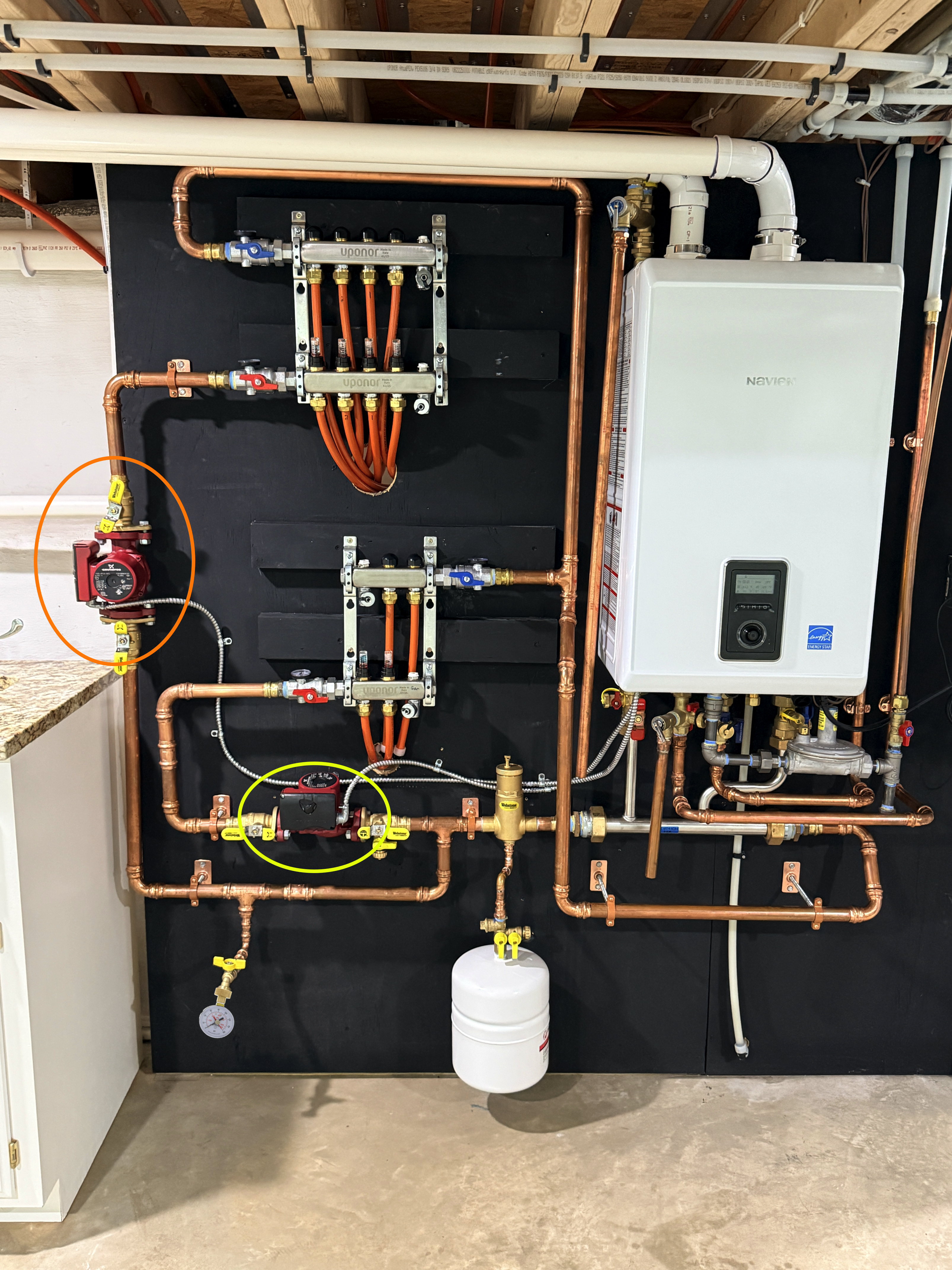
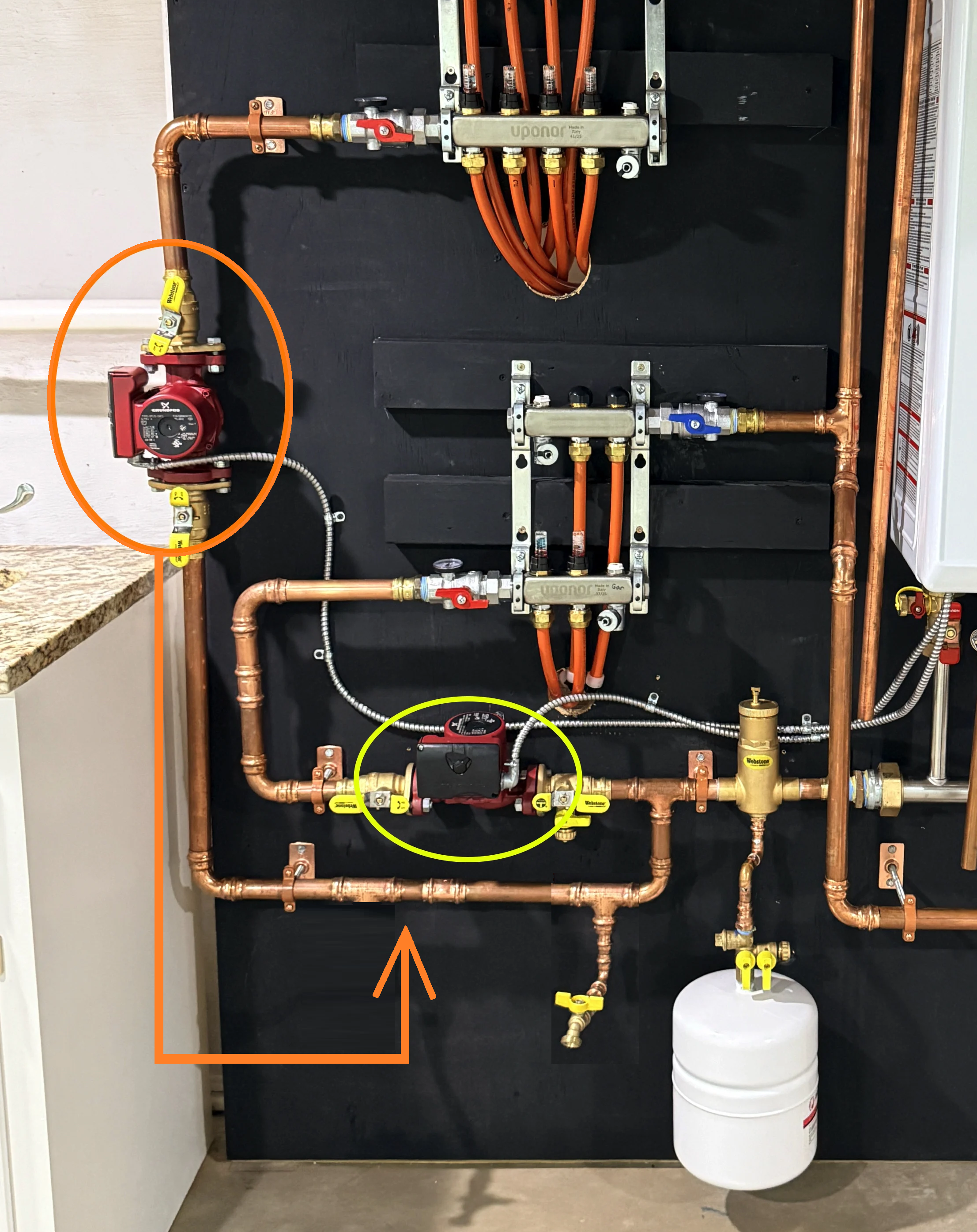
There is absolutely nothing wrong with the size of the pump. There is nothing to gain by changing the pump. I know you said that you're confident there is no air in the system, but you're too confident because there is most certainly air in the system. Unfortunately you did not have this professionally installed because no professional would have mounted the lower circ like this nor would they have foregone a purge station. When he comes back to fix the lower circ, have him install a purge station and properly purge the upper zone- it is undeniably airbound. Most likely on the return pipe above the upper manifold. Cutting in a manual vent there wouldn't be a terrible idea either, seeing as the "technicians" you've had out so far can't figure out how to properly purge the system of air.
0 -
I would normally say these kind of head scratchers are almost always air or pressure related. Someone already mentioned checking the ball valve for proper operation. Here's a simple test: Turn the isolation valve to the normal wide open position. Supposedly the flow stops to the upstairs manifold, and the flow meters go dead. Then try throttling the red supply valve on the manifold, or any other valve on that zone for that matter. If you can only get the system to flow with that one valve cocked a little, it's the valve. You can also shut off the isolation valves, and the red manifold valve, and inspect the isolation valve, even open it and shine a flashlight up inside. I've found Sharkbite insert stiffeners that softened up (should have not been used in the first place), then lodged in the piping crossways. You never know what you're going to find.
0 -
You have plenty of purge points. Pump directly through both manifolds with the purgre valves on the manifolds, that is why they are there.
Or pump into the Webstone valve at the small zone, through the piping and loops purge at the blue manifold.
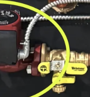
For the upper zone pump into the lower valve left of the expansion tank
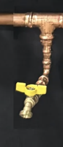
For the boiler piping pump into the valve at the bottom, left of the expansion tank, purge at the supply manifold.
The boiler may have a high point air vent inside?
The air purger will take care of the small bubbles that take days to come out of glycol solutions.
An Axiom fill tank would assure you keep pressure in the system as air purges for a few days. Heating the system also helps drive that air out of glycol.
With a wider pic I can maybe explain yet another purge method using the iso /purge valve under the boiler on the factory P/S header. I suspect there are two one on each drop?
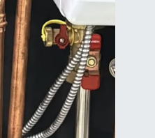
One purge valve at the return near the boiler would have simplified it, but what you have will work.
Don't change anything until you inspect the pump and flanges, then another purge.
Hopefully you have a pump able to move 4 gpm or so? A small plastic sump pump from Home Depot works well drop it into the glycol bucket.
The piping is nicely done, maybe the plumber doesn't have a lot of hydronic piping design experience.?
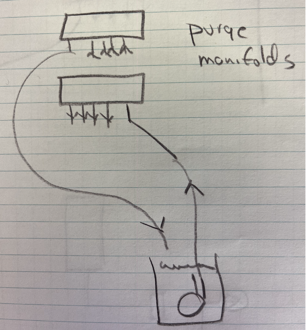 Bob "hot rod" Rohr
trainer for Caleffi NA
Living the hydronic dream 1
-
Yes, I will do what you guys recommend. Fix lower pump, remove upper pump inspect ball valve, purge system again very throughly. Thanks for the help. Gonna be a few days until I can get time to do it. Yes the installer is fairly new to installing hydronic stuff. I have one question though if the system was airlocked, why would water flow with the pump on system when the valve is throttled down? Thank you so so much for all the response very good useful information, much appreciated. 😃
0 -
Can I get away without a axiom filler, or do you think it should be added?
0 -
If you keep an eye on the pressure for a few weeks after you get it going. Often as small air continues to burp out, you need to "top off" the system pressure. Keep it at 12 psi cold.
A small pump like this would be enough to add occasional glycol. If the system is sealed, no leaks, at some point you will not need to add more glycol. Probably the least expensive option, if you own a drill of any type?.
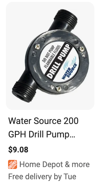
I suppose if you get the flow you need with the pump partially throttled, leave it like that. I don't have an explanation for that unusual condition.
Balance valves, even the ball valve type get cranked down to 50% in some cases.
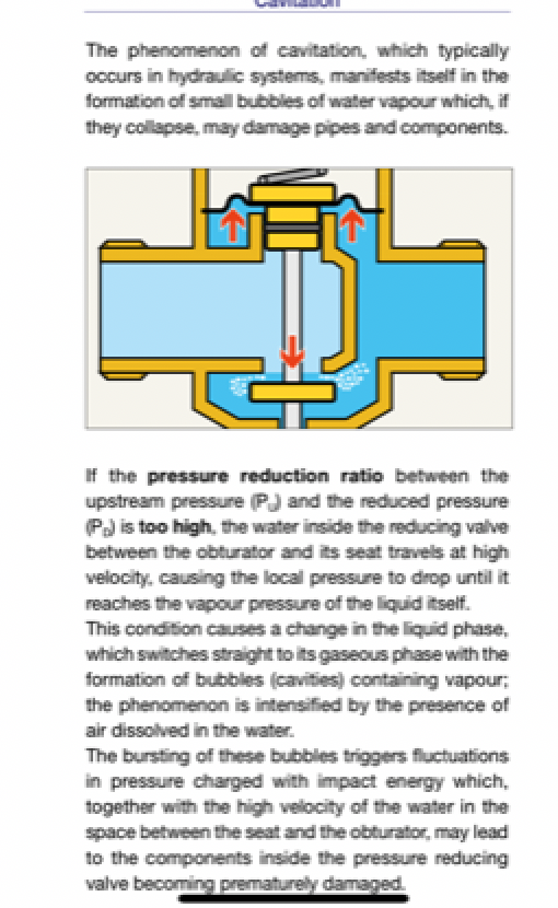
Beyond 50% reduction on a ball valve that you can get gaseous cavitation and noise, across the valve itself, explained below. it is a flow, temperature pressure depedant condition.
Keep the circ speed as low as possible to get the job done. From what you have shared, speed 1 should be adequate. Assuming again you are 300' or less loop lengths??
 Bob "hot rod" Rohr
trainer for Caleffi NA
Living the hydronic dream0 -
It may not be cavitation but if the system is way over pumped for that particular pipe size it could have to much restriction causing issues.
Closing the valve on the discharge reduces the flow so the pump can get suction. just run it with the valve partially closed.
0 -
Hi Ebebratt, that’s why I was wondering if I made installer change for ecm variable speed pumps, from my understanding they can pump much lower speeds, which could help?
0 -
You need 3 pieces of info to size a hydronic circulator
How many GPM is needed, the total of all your loop required gpm.
Head, the mechanical energy needed to move the fluid
Type of fluid, water, glycol blend
I don't recall your required gpm?? With 1/2' pex .50- .75 is best practice design
Head is determined by the flow resistance in the tubing and piping path, the actual loop length needs to be known
So with the assumption you need .65 gpm X 6 loops= 3.9 gpm
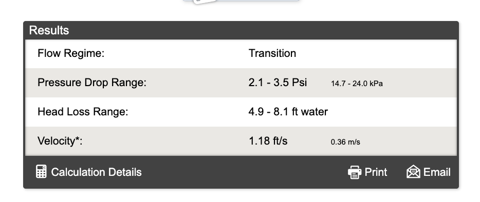
.65 gpm through a 1/2" loop, 300' of pex with 40% PG glycol = 8.1' (4.9 for water)
Use online calculators for the head if you do not have a desigh that gives you this info?
So you two numbers are 4 gpm at 8'
From the PPI, Plastic Pipe Institute, Flow Calculator
Next you find a pump curve for the model you are considering. i think you have a 3 speed Grundfos 15-58
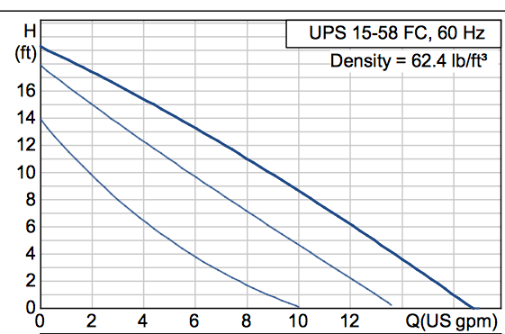
So enter at the bottom at 4 gpm, move up vertically to see where the curve crosses 8'. So you are just above speed 1
An additional step is to develop a system curve, which you plot over the pump curve. This tells you exactly where the pump will run on your specific system. Read through Idronics 16 to learn more about circulator technology and sizing, etc.
Using an ECM as a zone pump will reduce power consumption, it has a more efficient motor. You would adjust it the same way for the gpm and head your system needs.
Without more accurate info on your system, longest loop length, gpm required, and % of fluid all we can do is guess and make assumptions.
Multiple responses from hydronic pros tell you your pump(s) are right for the assumed application.
The installation and confirmation of your job needs to be done onsite, not much more we can do online to help until you supply more info.
The cover pic on Idronics 16 shows pump curves, red lines with the system curve overlaid, white lines. This is an ECM with multiple zone valves. It shows how the pump changes speed as zone valves open and close.
Bob "hot rod" Rohr
trainer for Caleffi NA
Living the hydronic dream0 -
Hot rod thank you so much for that information that is exactly what I needed. God bless you❤️
0 -
Place a water pressure gauge on the hose bib just before the pump in question to test the cavitation theory. Turn on the pump. If the pressure drops below 5 PSI, then your expansion tank is not properly charged and you could have cavitation.
Of course you will need to open that valve to read the pressure.
Edward Young Retired
After you make that expensive repair and you still have the same problem, What will you check next?
0 -
It's not airlocked, it's airbound. Throttling the valve offers a pressure differential reduction and allows some fluid to be moved, but it can't push all the air through that hoop above the return manifold. Purge it properly after the lower circ is rotated and it'll be good to go. No, you do not need any sort of makeup or feeder. If the system is properly purged of air and leak free, it will maintain pressure indefinitely.
0 -
If you have any movement at all in the system, you mentioned .7-.9 gpm? The air purger within hours will scrub out this dissolved or entrained air. Glycol takes more time. You might pull the top off that air purger and check for a stuck float or plugged vent.
The piping and components you have should scrub 97% of the air within a day or so.
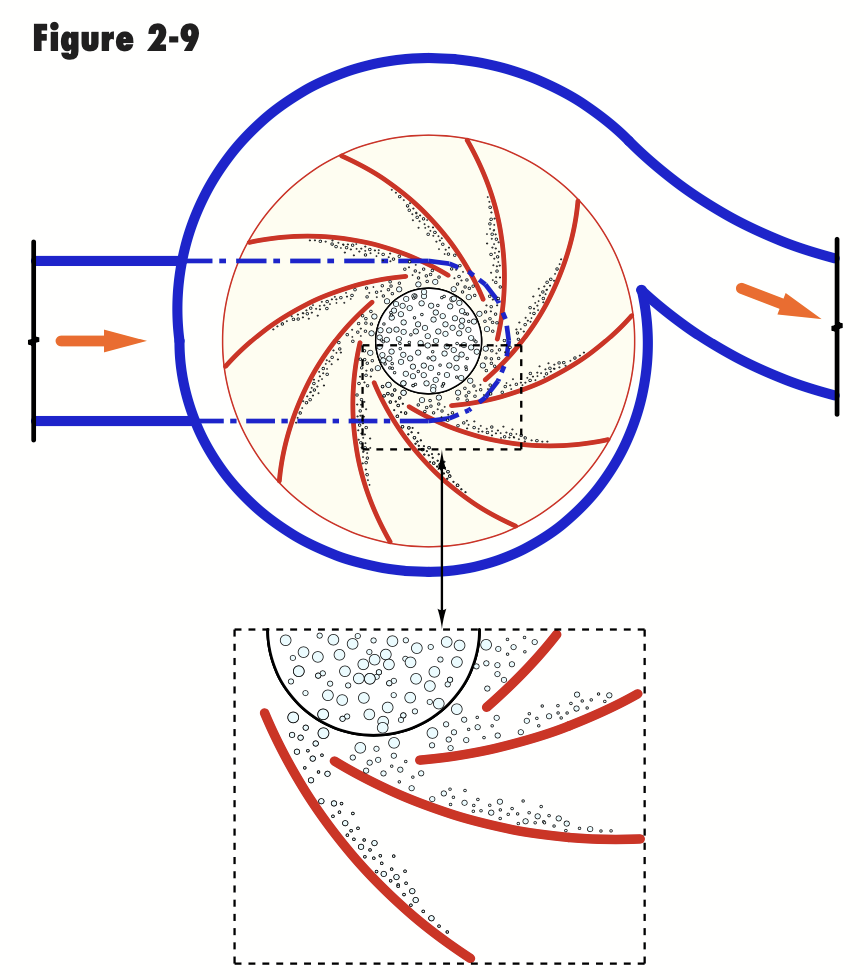
Closing down a valve on the discharge of a pump will reduce flow, no question about that. But it also will give you a bit of a velocity increase.
A demo of that is a flowing garden hose with and without a nozzle attached.
Without the nozzle you get max gpm. Install a nozzle flow (gpm) decreases but it sprays across the yard. You substituted gpm for fps feet per second velocity.
Basically the principle of an orifice. An orifice in a balance valve increases the speed across the orifice. Read the pressure on both sides of the orifice to convert to gpm.
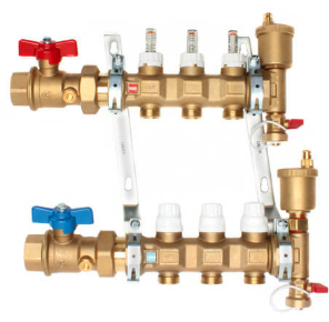
Mainly a start up purge mechanism, the Caleffi manifolds include float style auto vents to grab air right at the loops.
 Bob "hot rod" Rohr
trainer for Caleffi NA
Living the hydronic dream0 -
HEY, hotrod thanks for the info. Yes the system if i turn just pumps on and leave the said ball valve throttled down water moves, i left it running for about 2 days however when i open valve fully all water flow in the upper loops stop. I am not home for a few more days then i will bleed again, however i had a question when a system is cold at 12psi hot with pumps running how much should the pressure climb? I believe mine jumps to about 22psi is that normal for a system with expansion tank?
0 -
also yes the uponor manifolds have the air bleeders on supply and return. Thanks much
0 -
Static pressure is the measurement of the pressure when the water or fluid is not being circulated. Basically a measurement of the weight of water. So if you fill the system to the uppermost point, a gauge anywhere in the system is measuring the weight of the water aboive that location.
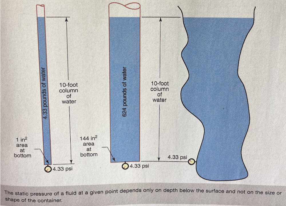
Your fill valve can add addition pressure to that static measurement, static fill pressure. Most fill valves are pre-set 12- 15 psi depending on the brand.
When a circulator is switched on, system purged, it adds head, mechanical energy, to the system. As the fluid flows through the piping circuit, that energy added by the circ gets used up, dissipated, by the resistance the piping, valves, devices present.
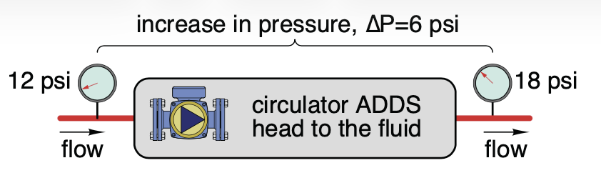
So the pressure(s) you measure depends on where in the system the gauges are located.
The amount of pressure increased by adding "head" depends on the specific pump and piping it is connected to.
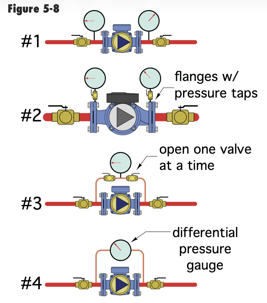
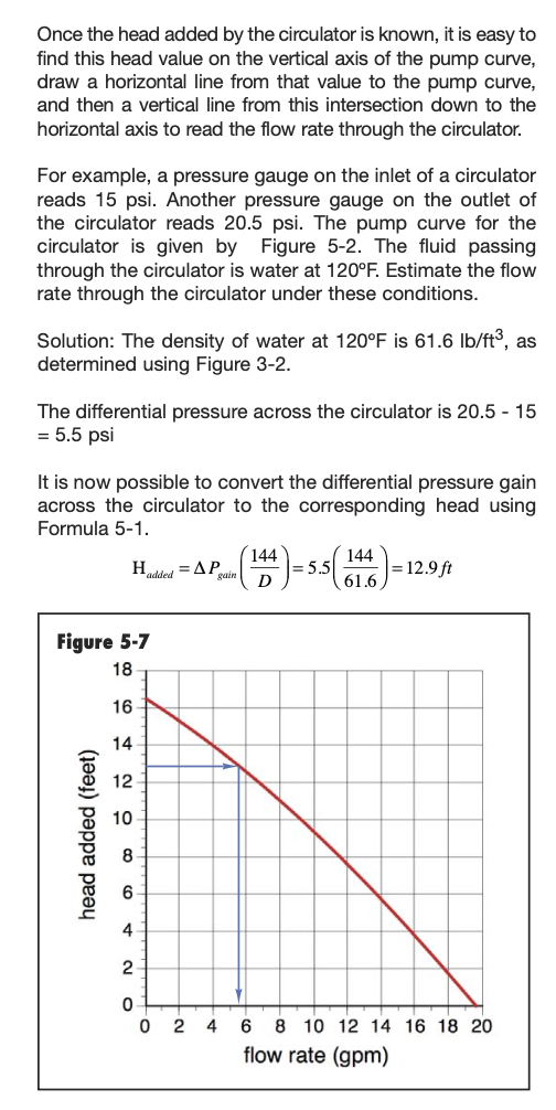
A gauge right at the inlet and outlet shows the differential pressure, put into a formula and with the pump curve, you can determine the actual gpm the circ is moving
When you pump away from the expansion tank that "head" shows up as a pressure increase. As fluid flows around the loop green line on drawing, see how the head is used up. The pump added 8 lbs, so discharge gauge reads 18
7 psi was consumed around the loop, pressure at return reads 11 psi.
But pressure at the expansion tank never drops below the static fill pressure. . The only way that pressure changes is you add additional fluid. You remove fluid. Or you change the temperature of the fluid.
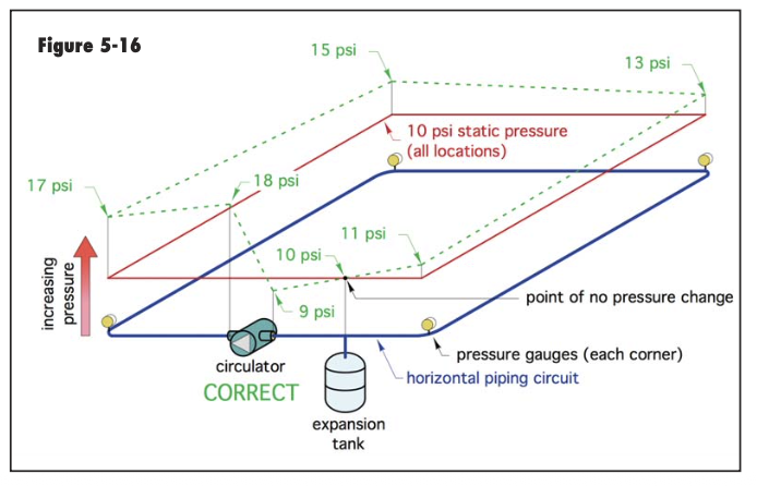
When a circulator starts within seconds hydraulic equilibrium is reached when the rate of head added equals the rate at with the system dissipates this head.Flow rate at this condition will remain constant.
If you have a chance to read Idronics 16, all this is explained in layman terms :)
An under or over-charged expansion tank will not change the circulation. Under-charged some fill water enters the tank. Over-charged it may not accept the thermal expansion, relief valve may pop.
Still the key is to assure the system is filled, pressurized and purged. Confirm the pump is installed in the correct orientation, that the impeller is spinning. No valves or strainers are obstructing flow.
Bob "hot rod" Rohr
trainer for Caleffi NA
Living the hydronic dream0 -
Hi hotrod love the info, I am reading the book you said to very good information in there. I was thinking for an energy efficient system how much of tempetrue drop from supply to return do you like to see, I have seen some say 10 degrees and uponor recommends 20 degrees.
0 -
Zone 1:
Office loop 275 feet
Bathroom 275
Living room 1: 245
Living room 2: 240
Zone 2:
Garage loops 1 390
Garage loop 2 390
I got the exact lengths of all my loops. 30% proplyene glycol just stating so it’s on record here.
0 -
Loop length info helps with some numbers, thanks.
The radiant delta is more about comfort. The tighter 10° give you a more consistent floor surface temperature compared to 15. However it will cost more pumping power.
For the garage with those long 390 loops a 20- 25° is fine as you are probably not out there barefoot? Two loops in the garage? What is the square footage?
The garage loops at .65 gpm flow will be around 10' head, still within range of your 15-58.
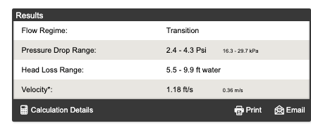
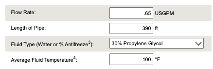
Still not finding any issues with design piping or current pump selection.
Bob "hot rod" Rohr
trainer for Caleffi NA
Living the hydronic dream0 -
800 sqf garage, I layed the piping for that and layed it in a way that if one ever burst the whole garage could be heated by a single loop, but the result was it got a little long on both, but yeah won’t be barefoot out there
0 -
one question the idronic 16 book made it sound like if velocity under 2ft/s it makes it hard for air to be pushed out and at a 1.18ft/s air can just get stuck in the loops? Is this accurate? If so how do I raise velocity to pump that air out better?
0 -
If a shop is going to have plain water, knowing that loops at the overhead door are most at risk, constant circulation is easily accomplished with a 3 way zone valve. Some prefer running a small circ to a glycol solution. Put it on a UPC if power outages are a concern
Here is my shop manifold. Hot or chilled water circulates for heating and cooling.
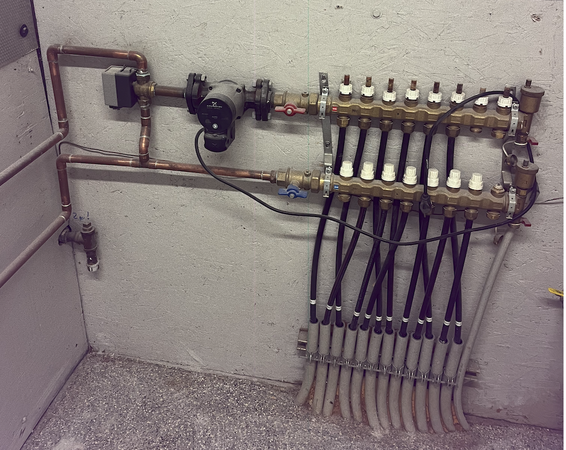 Bob "hot rod" Rohr
trainer for Caleffi NA
Living the hydronic dream0 -
yeah good to know very nice setup you got!
0 -
System pressure should not fluctuate at all, in a properly installed system. Hot, cold, or otherwise should stay at the same pressure. A couple PSI is acceptable, but 10 is not.
Once again, the loops need to be purged with an external pump to gather enough velocity to force air out. This should not be your issue to fight with- get the installing contractor back and make them fix it. If they don't, get a lawyer involved.
0 -
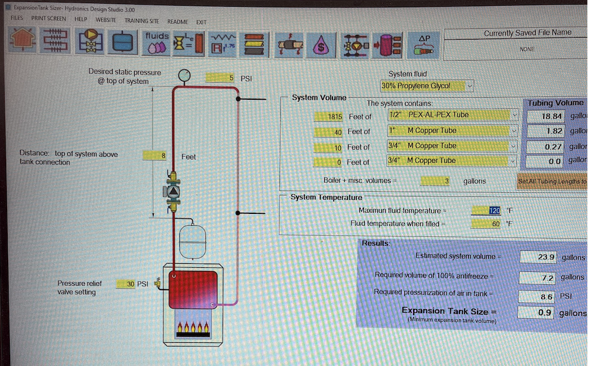
I'm guessing your system holds about 30 gallons, 18 gallons in the tubing, misc piping and boiler capacity.
If the high point is 8' above the boiler you need to pre-charge the tank to 8.6 psi, system glycol fill to 8.6 psi.
This assures you have 5 psi at the highest point in the piping.
Water/ glycol will expand as heated, contract as it cools. So pressure will increase.
A properly sized tank would allow pressure to increase to 5 psi below the relief setting, to 25 psi.
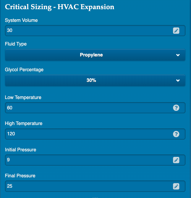
Using the online Wessel tank sizer, you can plug in an initial and final pressure :
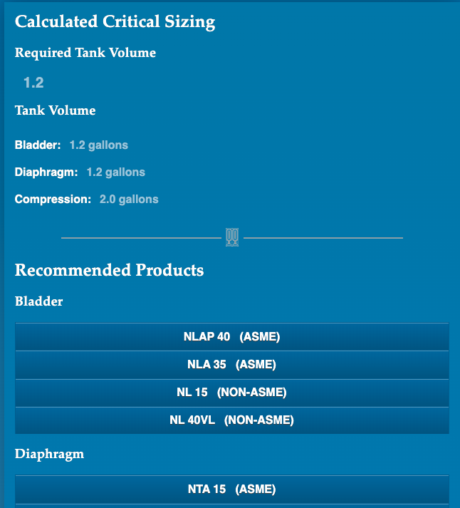
So from 9 psi fill to 25 psi at 60- 120° would need a 1.2 gallon expansion tank, a #15
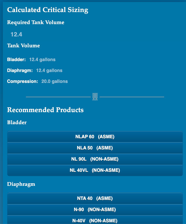
If for some reason you wanted only a 1 psi increase from 9- 10 psi across that temperature range you need a much larger 12 gallon tank.
A #30 tank would be my choice for a bit extra capacity, lower final pressure, a wider temperature spread.
The Wessel calculator does not accept a starting ad final pressure of the same valve.
 Bob "hot rod" Rohr
trainer for Caleffi NA
Living the hydronic dream0 -
I guess only thing I’m not sure on is there is no physical pressure gauge just the digital read out on the Navien boiler (idk how accurate that is or if that’s after the pump so showing increased pressure “when warm, because pump is running too???”)
0 -
As you heat the fluid, pressure will increase, even without pumps running.
Start the system cold, what is the pressure?
Run the boiler until it reaches setpoint. Turn off the pumps. I'm betting the pressure has gone up.
How much depends on the expansion tank size and accurate matching pore-charge pressure.
The procedure I outlined a few posts up shows a reading across a pump when it is running. That shows you have flow and you can calculate how much flow with that pressure differential number.
If your system reads 8 psi or more cold, no pumps running, and never drops below that the system is pressurized.
But it can be pressurized and still air bound or partially air bound, so little to no circulation.
Reducing the flow, what ever amount you have at the pump discharge will not, cannot increase flow in the loops.
You mentioned .7- .9 gpm on the manifold flowmeters?
Bob "hot rod" Rohr
trainer for Caleffi NA
Living the hydronic dream0 -
is the check valve on the yellow circulator bad or missing?
0 -
you can buy or build a hose connection gauge like this, swap it to a 30 psi gauge
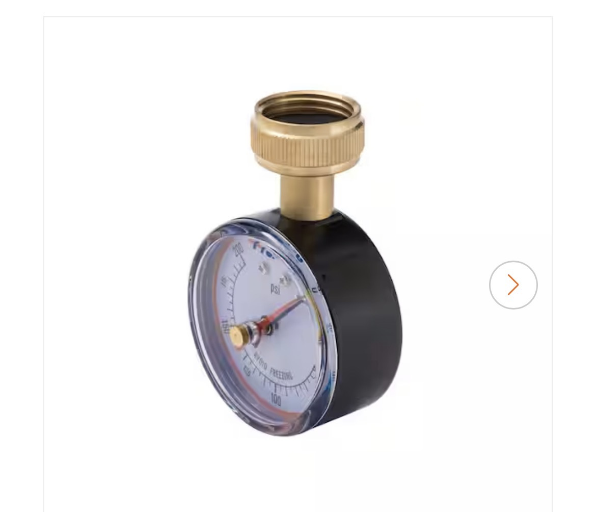
Or build one up eight a hose adapter 1/2 x 1/4 bushing and gauge
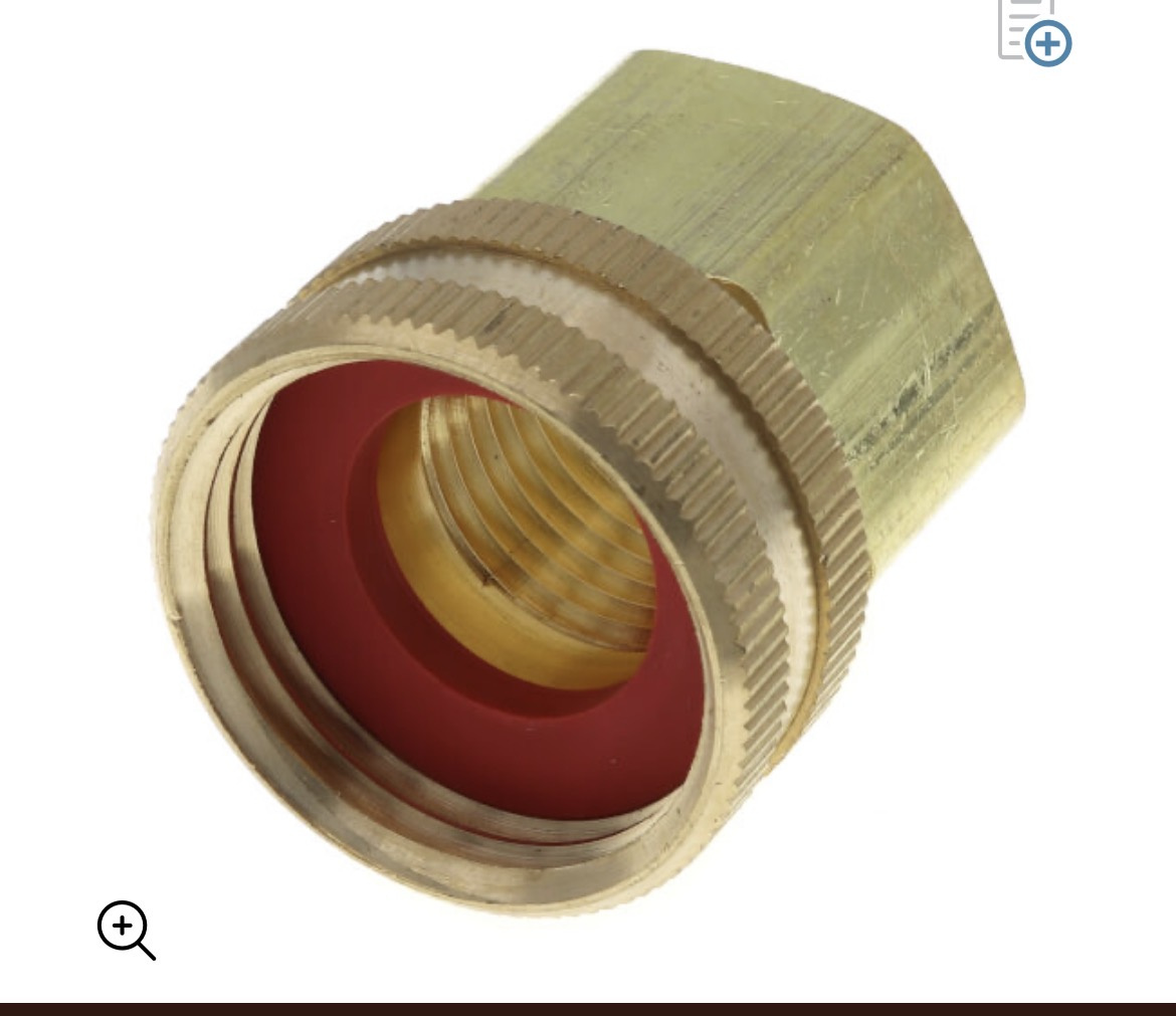
Confirm that the boiler gauge is accurate with it, and move it around on all the hose connections you have to observe pressures in different locations with pumps running
You need to start collecting accurate data to answer your questions
Bob "hot rod" Rohr
trainer for Caleffi NA
Living the hydronic dream0 -
yes I love that idea, I will get on that as soon as I am home thanks so much for all the information and being so helpful! I am forever appreciative.
0 -
plumber came back and lower pump is fixed now in correct position
0








Categories
- All Categories
- 87.8K THE MAIN WALL
- 3.3K A-C, Heat Pumps & Refrigeration
- 60 Biomass
- 430 Carbon Monoxide Awareness
- 133 Chimneys & Flues
- 2.2K Domestic Hot Water
- 6K Gas Heating
- 124 Geothermal
- 170 Indoor-Air Quality
- 3.9K Oil Heating
- 79 Pipe Deterioration
- 1.1K Plumbing
- 6.7K Radiant Heating
- 397 Solar
- 16.1K Strictly Steam
- 3.5K Thermostats and Controls
- 56 Water Quality
- 51 Industry Classes
- 51 Job Opportunities
- 18 Recall Announcements