Church Radiant Ceiling Help

We take care of the heat at this complex. There is an existing (1950's or 1960's) sanctuary heating zone with copper radiant ceiling. The ceiling is arched, approximately twenty feet above the floor. It appears as the ceiling is plastered, although they are taking care of asbestos abatement as I write this. I guess it is possible that the ceiling installer added asbestos to the plaster. Despite the age, this radiant ceiling works excellent for the most part. In the eight years we have been servicing this account, we have needed to make repairs to the copper radiant on one occasion for a pinhole leak (this was about five years ago).
Over this past winter, an area below the sanctuary lost heat and many heating and domestic pipes froze and burst. This was a brand new renovated section, that consists of four large restrooms. While investigating, the Church's insurance company noticed part of the ceiling in the sanctuary was damaged, possibly from the extremely high moisture in the building. The ceiling was flaking onto the floor (and the pews). They tested this ceiling material and found traces of asbestos.
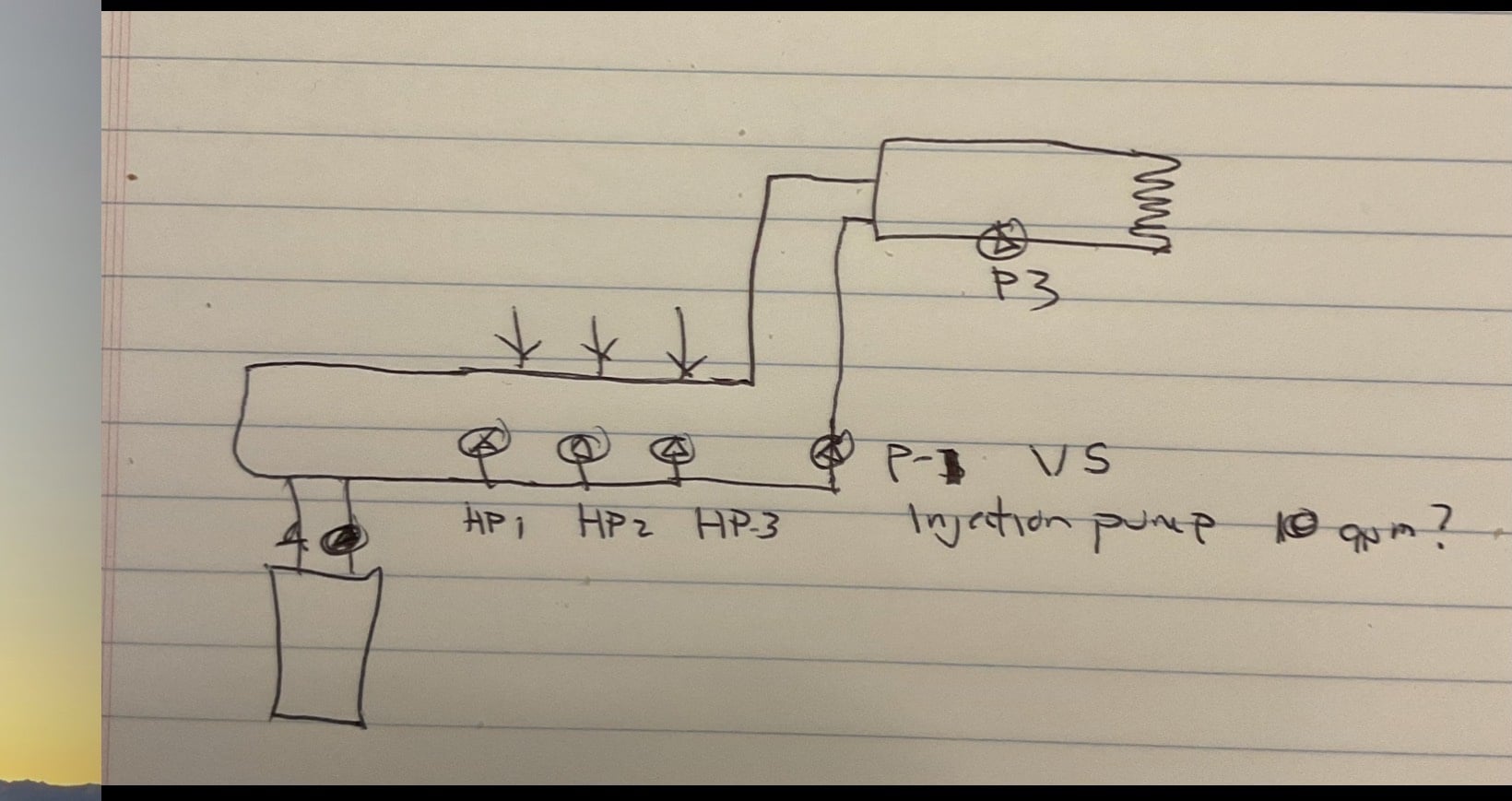
We have been asked to design and install a "better" control and circulating system for the Sanctuary zone. I have attached a sketch of what I think may work best. Currently, for P-3 they are using circulator that appears to be an older B&G HD-3 (possibly original) and a 2.5" steel supply and return (from the boiler room). For P-1 they are using a Taco 0010, with one inch steel pipe. There currently is no P-2, we plan on adding this circulator and 2" piping off the existing header. The insurance company engineer is concerned that they Sanctuary ceiling radiant might be running too hot. The engineer suspects the high radiant temperature may be destroying the ceiling. Perhaps the engineer is concerned the new "plaster" will not handle the heat as well as the old "plaster?"
Our tentative plan is to pipe the system as drawn. Most of the drawing is existing with the exception of the missing P-2. I skipped showing the flow checks, isolation valves, etc. to simplify things. I think a Tekmar 361 to control P-1 (injection pump) and P2 might be a good fit for this project.
I welcome your comments on the design. I am also unsure of the sizing of P-2 circulator and piping. Do you feel the P-1 (0010) is properly sized? I am considering replacing P-3, based on the age of the pump. I suspect this (P-3) is actually sized correctly as it still operates after sixty years.
Thank you,
Scott
Comments
-
by the 50's the various layers of plaster materials were mill mixed products that came from a factory and they added asbestos to various formulas of the different layers for various reasons. they also used vermiculite as the aggregate in lightweight base coat plaster which was frequently contaminated with asbestos. Is the plaster on expanded metal lath or rocklath or what? The expanded metal version makes it very strong.
0 -
I have not been in the attic myself. However, I was told that there is expanded metal that the copper tubing was rubbing against that may have caused the leak we repaired years ago.
0 -
A little confused on your circs. In one spot you mention P2 is an 0010 then you mention p1 is the 0010?
Anyhow I would start with a HL of the Sanctuary and evaluate the radiant (if you can). This will determine the pump flow needed. Sounds like the goal is to limit the HW temp to avoid degradation of the ceiling which I agree with.
To my way of thinking P2 only needs to be slightly larger than P1 to avoid water "backing up" across the bridge. P1, P2 and P3 are not needed for the office, basement and common zones.
Are you thinking all these zones need 180 degree water to satisfy the heating loads? The Tekmar is only controlling the sanctuary correct?
0 -
in that era in commercial buildings expanded metal lath wired to hanger iron would have been very common and the radiant tubing was probably wired to the lath then they embedded it in the base coat of the plaster.
0 -
I apologize for the wording and labels. In English, the existing pump that takes care of the radiant loop is a B&G HD-3 (labeled P-3). The previous contractor installed the Taco 0010 directly off the boiler header to act an injection pump. They run the B&G all winter and control the Taco with a Nest thermostat.
With regard to the heat load, I calculated 322,000 BTU worst case. 258,000 best case. We are stuck with the roughly ten year old Weil McClain 788 boiler. The other zones certainly need 170 or 180 degree water on design days. In addition, they want to leave the building at fifty degrees when unoccupied. I suspect the engineer for the insurance company (and me) prefers to at least keep the sanctuary at least 65 degrees when unoccupied.
@mattmia2 I agree with the construction methods. makes sense to me.
0 -
So the boiler loop is a primary loop? Or not? I'm not clear on the dotted line at the top?
Bob "hot rod" Rohr
trainer for Caleffi NA
Living the hydronic dream0 -
There is no "boiler loop" at the moment. They are currently pulling heated water at whatever temperature the boiler is providing. This is true for all of the heating zones.
Please see attached for the 'current' piping method. Regarding the dotted lines, I believe Taco HSS software uses dotted lines to show lack of flow or poor design. If I used "Taco Twin Tees" the dotted lines disappear.
0 -
i don't know what the right temp for a radiant ceiling is but I do know it isn't 180f.
if that is really what is happening the boiler almost certainly is getting return water that is too cool.
my bet is that the radiant loops don't actually get anywhere near 180 and you are condensing the boiler.
0 -
is there a pump at the boiler, ehere ut dhows 67 ,9 gpm?
If so, that pump is in series with whatever zone circ is running. I don’t see any hydraulic separationEstablishing separation would allow multiple temperature and possibly boiler return protection
Bob "hot rod" Rohr
trainer for Caleffi NA
Living the hydronic dream0 -
No boiler pump, hence the new design. I guessed at what the Taco 0010 was flowing for gpm and head.
I believe the first drawing will work fine, similar to what Tekmar shows. Do you agree? With relatively large (three inch) near boiler piping, I don't think there would be issues.
0 -
If the dotted lines are pipe I think your fine
0 -
Not sure on injection pump size, but I think Ziggys software will help with that.
As far as boiler loop goes, I'm unsure. I'm guessing large diameter pipe is best, roughly two inch? What kind of flow? I'm guessing almost no head loss.
0 -
I was thinking a loop like this to assure the boiler flow.
If direct piped, would the 10 gpm injection pump be adequate for the boiler. Does it have a minimum flow required?
 Bob "hot rod" Rohr
trainer for Caleffi NA
Living the hydronic dream0 -
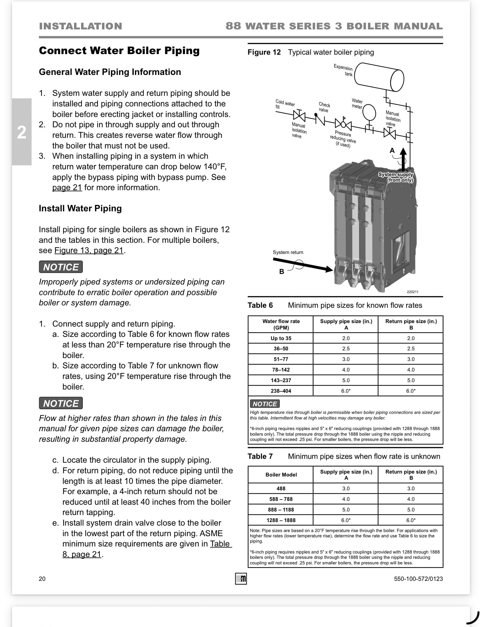
it is a ci boiler so it doesn't have a minimum flow per se but you do need enough flow to get all of the heat out of it.
0 -
the piping info talks about a 20 delta across the boiler. With just the ceiling radiant running, it seems the boiler may be underflowed?
Scott works with this sized stuff, he would have some idea of required flow on a 788K boiler
 Bob "hot rod" Rohr
trainer for Caleffi NA
Living the hydronic dream0 -
are you showing the boiler pump as a variable speed that does injection mixing? it seems like you would want to run it on the rwt? but you also need to control the temp to the radiant too so i don't see 2 temp controls, either through vs circulators or thermostatic/modulating valves, granted i didn't read super closely abd the sketches are just rough sketches so i might have missed something.
0 -
I must be missing something
The drawing shows the boiler at 662,000 and 67 gpm which is a 20 degree TD
The sanctuary is 330000 btu with a 33 gpm pump same TD
Tf the boiler runs 180s and 160 return and the sanctuary is the same water temp at 20 degree TD
Then the injection pump would need to be the same size as P3 or slightly higher to prevent backflow on the bridge.
Usually only have injection pumps if the water in the secondary loop is held at a lower temp than the primary.
0 -
I think the radiant needs to run more like 135- 115, then plug in the radiant load to do the calculations
Bob "hot rod" Rohr
trainer for Caleffi NA
Living the hydronic dream0 -
am i missing a decimal somewhere or is that boiler like 1.7 million btu/hr, making it like 3x the size of the connected load?
0 -
Many ions ago when people thought seriously about liability of what they did there where always a extra layer of protection to cya . Now adays i don t think i ve 1 radiant system where one of the basic things where including to protect floors and cieling from damage due to over temp issue w radiant . All it really takes is a secondary hi limit on your radiant piping supply . It can be set for 10 degree over your max ceiling or floor temp and also set a differential . Now a days i would not use a honeywell aquastat i find them to be highly inaccurate ,personally i ve been using ranco etd controller and have never had one issue. in the old days i would use a manual reset hi limit but as stated i find them highly inaccurate and costly and now made in china resideo while a ranco etd is about 1/2 the price and very accurate and in bout 30 years of using then for various application i have not seen one die w a keypad lock out and a adjustable diff ya just can t go wrong . i stictly use only the 110 /208 verision the 24 v one is just one more thing to fail . in days of old most radiant floor system had showed a manual hi limit to protect floor now nobody even shows it in diagrams or things about it . But in that same though ya spend 15 k on a couple of rooms of radiant but there s zero money for secondary limits or even decent manifolds but when the floor is damaged from over heating they got money for a lawyer . Way to funny for me
peace and good luck clammy
R.A. Calmbacher L.L.C. HVAC
NJ Master HVAC Lic.
Mahwah, NJ
Specializing in steam and hydronic heating
 2
2 -
I went to bed last night and could not fall asleep thinking about this job. When I got to my office this morning, I downloaded the newest version of Taco HSS software to my relatively new desktop computer. The monitor is enormous and makes it much easier than using my laptop (for me with lousy eyes).
I updated my initial post as I screwed up the pump identification numerous times. Please see the latest drawing for what I plan on proposing to the engineer. I think it will make more sense as it is a little more accurate. I only did a heat loss calculation for the Sanctuary. I estimated the heat loss for the other zones, all large cast iron radiators.
0 -
@clammy based on your post, I think I may add a Ranco controller as a safety.
0 -
That looks much better.
0 -
Your drawing shows a primary loop with close tees, or Taco tees, that works. 33 gpm from P-2 may not get a 20∆ through that 662,000 boiler, assuming it is a single stage firing?
1" would be adequate for the injection loop, just over 10 gpm..

In your drawing your high temperature loops are parallel to the primary loop.
Seems those zones should be sets of tees off the primary loop? Or else P 2 may, probably will push some flow through the HP zones. Idronics 19 talks about a boiler primary loop with parallel secondaries.
I think what you are trying to accomplish is equal temperature to all the HP zones? So taking those off the primary loop as closely spaced tees would present temperature drop, depending on which zones may be calling at any time. So a series primary loop is not an option.
My chicken scratch drawing at the bottom shows the boiler "injecting" into a loop that assures all zones get the same temperature. They are parallel loads. Then a injection loop for the ceiling zone at 140 SWT. 45 gpm around the loop, 2" may be adequate?


 Bob "hot rod" Rohr
trainer for Caleffi NA
Living the hydronic dream1 -
@hot_rod IDK the main being 3" is way oversized for the flow. I don't see much pressure drop across the 3" at that flow.
The circs on the 3 HPs added to P3 give him the 66 gpm he needs for the boiler
0 -
but the boiler only gets 66 gpm when all HP are running?
And they are in series so what gpm goes to HP 1,2 and 3?
Checks will be needed at all 3 HP or you can get reverse flow
If the system is getting repiped, why not do it correctly? What is the downside?

You are talking two tees at the boiler to make an accurate p/s. The boiler gets the flow it needs always, no pump interference in the distribution, no potential ghost flow.
The installation manual does show a bypass pump to assure the boiler gets enough flow. P/S solves that concern also.
Although the boiler may short cycle it’s brains out on low load conditions if it is twice the required size?
Bob "hot rod" Rohr
trainer for Caleffi NA
Living the hydronic dream1 -
Yeah your right.
0 -
just remember to size flow through copper tubing to purge air out, as there is not an air bleeder at top of curved portion?
0 -
two modcon 400,000 boilers, or 3 - 3000,000 boilers.
0


Categories
- All Categories
- 87.9K THE MAIN WALL
- 3.3K A-C, Heat Pumps & Refrigeration
- 60 Biomass
- 430 Carbon Monoxide Awareness
- 133 Chimneys & Flues
- 2.2K Domestic Hot Water
- 6K Gas Heating
- 124 Geothermal
- 170 Indoor-Air Quality
- 3.9K Oil Heating
- 80 Pipe Deterioration
- 1.1K Plumbing
- 6.7K Radiant Heating
- 397 Solar
- 16.1K Strictly Steam
- 3.5K Thermostats and Controls
- 56 Water Quality
- 51 Industry Classes
- 51 Job Opportunities
- 18 Recall Announcements