Cast iron system not heating well

Ive inherited a home that has been known for decades to not heat well. I would greatly appreciate if y'all could help me figure out what the problem is.
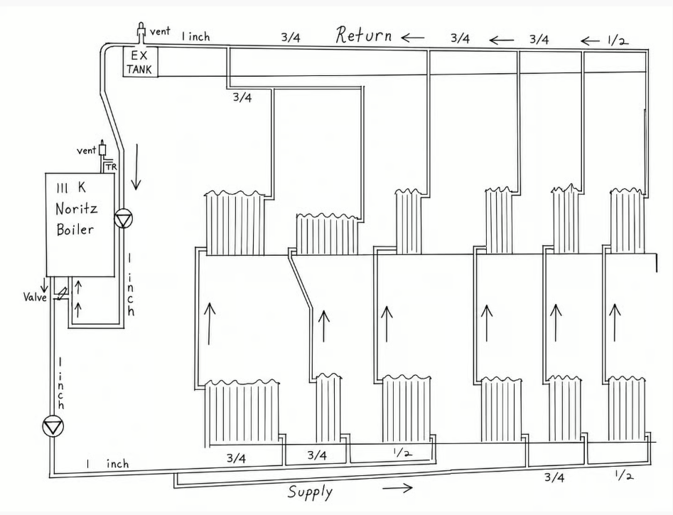
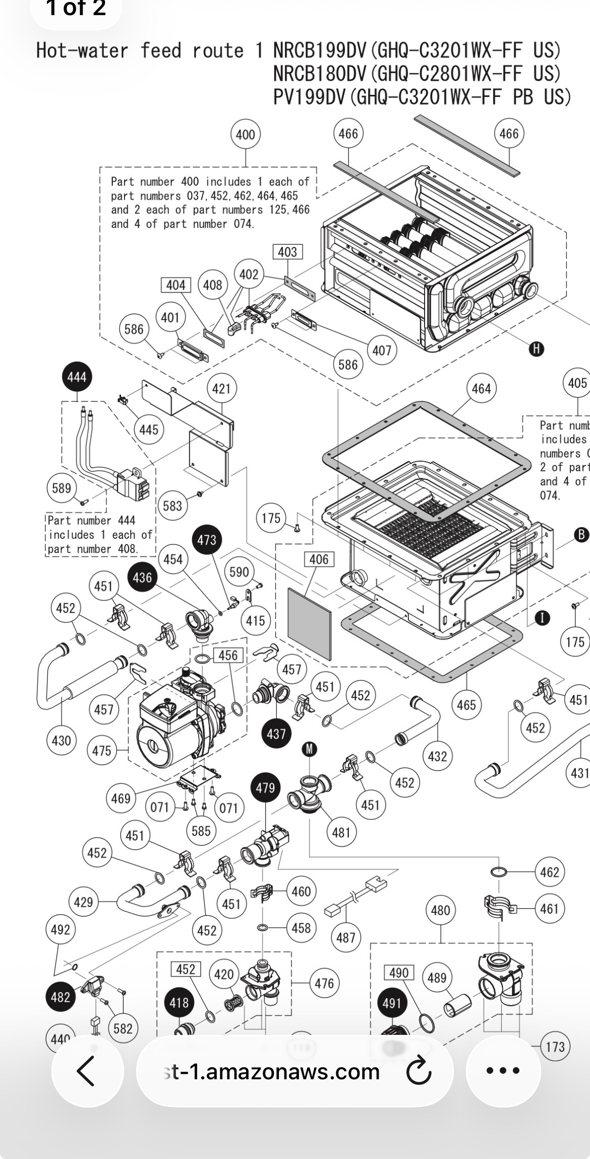
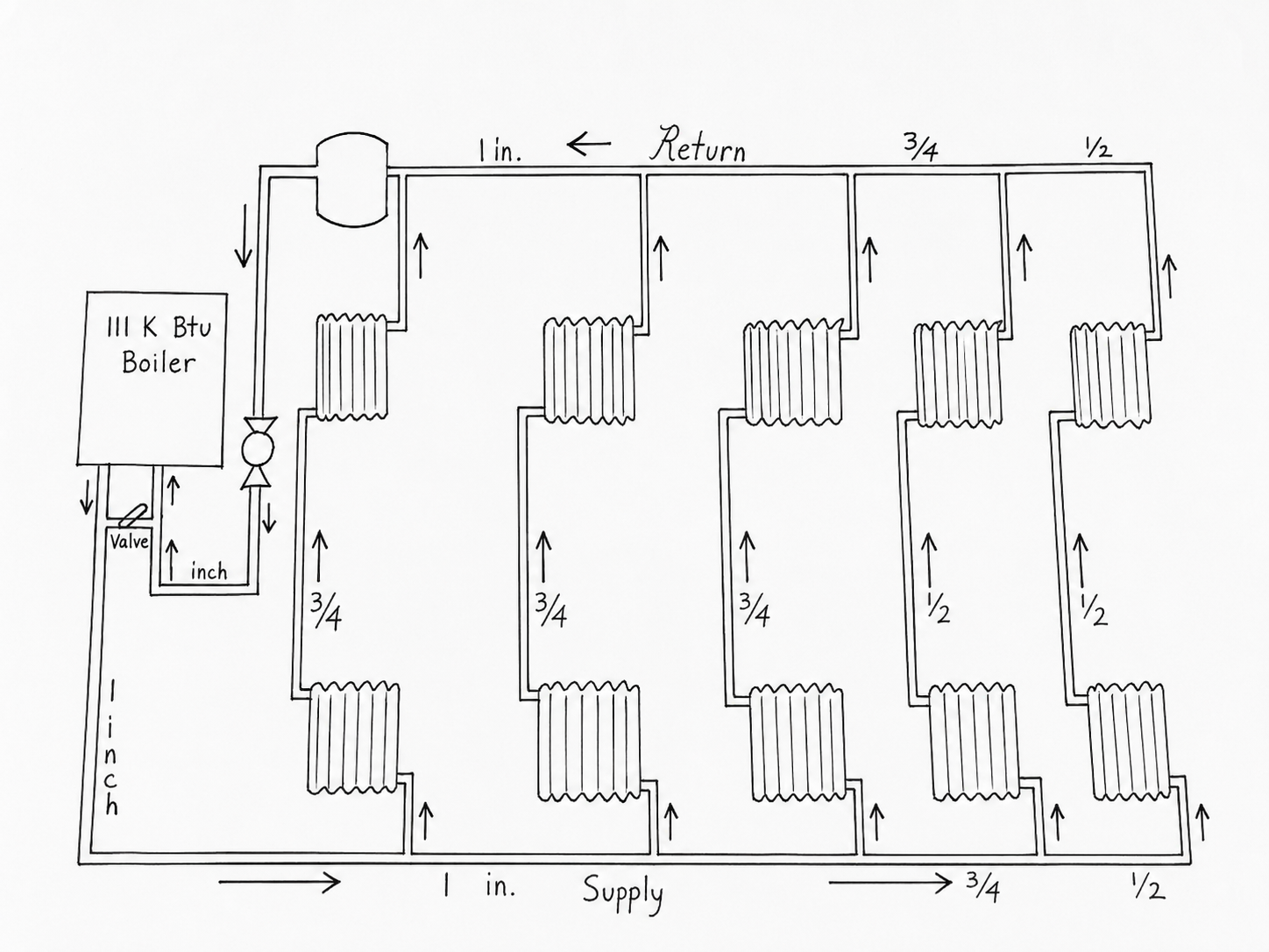
2,500 sq ft house. 600 EDR of cast iron radiators. 111k heating combi boiler. The system as a whole does not flow well. The last radiators have problems freezing even with all the others throttled down.
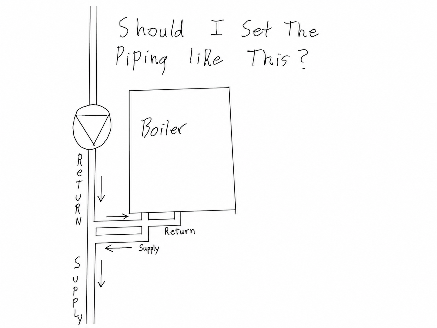
When i open the "valve" all the way near the boiler, the heating water short circuits into the boiler
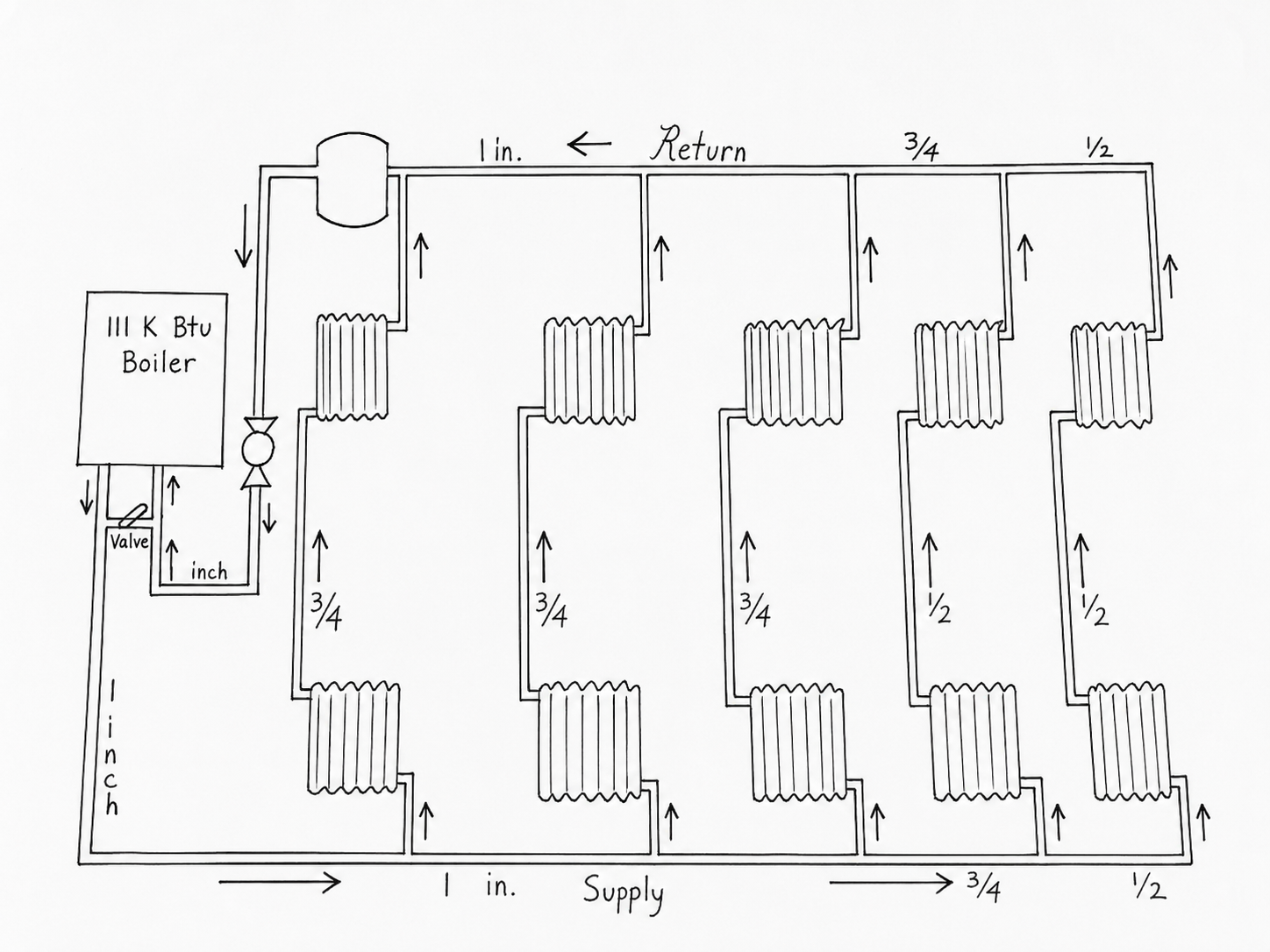
return and never makes it into the system. The system only heats when the valve is closed and all water is routed through the boiler. It being a combi, this creates a big flow issue. I have included a diagram. Can anyone point me in the right direction? Thank you. -Jon
Comments
-
is it a conventional combi such as is somewhat common in europe vs a condensing boiler?
does the boiler have a built in circulator?
0 -
might be best to have primary secondary or a hydraulic sep.If it is a combi, it has a pump inside.
But it may not have the capacity to flow the boiler and distribution piping.
The boiler manual should have some piping info.
Bob "hot rod" Rohr
trainer for Caleffi NA
Living the hydronic dream

 4
4 -
It is a noritz nrcb199dv. It has a built in circulator as well as a seperate circulator in the system piping. This problem has existed years before this boiler was installed. It is piped primary secondary, but will not heat unless the bypass valve is closed. Effectively making it no longer primary/secondary.
0 -
You need to make the system "primary secondary" to make it work.
The boiler loop has to flow enough water to keep the boiler happy.
The heating loop need to have enough flow to satisfy the radiation. You may need balancing valve on the radiation loops if you don't have them.
You need to have 2 circulators if you only have 1 you will have issues
too bad that the radiation furthest from the boiler is 1/2" which will make it more difficult to balence but it may be ok if sized properly.
Combis and condensing boilers have a large pressure drop.
need more info on the # of pumps and pictures of the boiler piping.
 1
1 -
where are the radiators physically located? are they on multiple floors or all one level? are the ones shown above and below in your diagram physically above and below? is the return piping above? it may be very difficult to get enough flow to purge the system and you may need bleeders on the piping if the radiators aren't the high point. if you do purge you probably need to open only one pair of radiators at a time.
0 -
you probably need around 10gpm through the boiler to move the output of the boiler. yo may need more in the system to make it even although if parts are actually freezing it is probably air bound or has broken valves or something like that.
0 -
but what you have is not primary secondary. you have 2 circulators fighting with each other and a valve trying to play referee.
0 -
The radiators are physically above one another on two different floors. The piping in the attic is sloped upward with the highest point having a bleeder vent. I should have put that on the diagram. It shouldn't be air bound. The way it is piped, almost everything is self bleeding.
I am not sure if it is piped or pumped correctly, as it has had many attempts to make it heat better.
0 -
you also might not have enough circulator for that system. many people just use a taco 007 and it usually is close enough but you might need more flow.
the valves may not be fully off when they are off, many valve have a tiny bypass built in to keep the radiator from freezing when the valve is off. if you don't have enough circulator that could be enough to keep the far radiators from heating.
having the radiators stacked on 2 different floors poses a balancing problem because the load on the 2 different floors won't be the same but obviously you are controlling flow in both when you try to balance. ideally they would have selected radiator sizes to keep them more or less balanced.
0 -
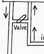
This piping topology looks like a remnant from a non-condensing cast iron boiler system.
I would not consider that as closely spaced Tees.
Does the boiler short cycle ?
Internal circulator running when expected ?
 National - U.S. Gas Boiler 45+ Years Old
Steam 300 SQ. FT. - EDR 347
One Pipe System 1
1 -
What you have is not primary/secondary, although it's not always necessary if the onboard circ can provide adequate flow to cover the load.
It sounds like you've tried balancing flow, but to clarify, if you close off every radiator besides the ones in question are they still cool? There is obviously a flow problem somewhere, but narrowing that down will require some diagnostics. Assuming the circ is adequately sized, there may be a blockage in the piping or rad(s) somewhere. While uncommon, I have seen a few times where sludge builds up in the base of the rads and inhibits flow. Several times I've found debris in the piping (usually against an elbow or valve) that was accidentally left in there during construction. Once upon a time, I found the metal end cap of a fitting brush wedged in the cup of a fitting that must have broken off of the brush during cleaning prior to installation.
0 -
The only thing i am certain about is all the air being purged. Boiler, radiators, piping. And the radiators being balanced. Ive calculated EDR, and they are all about right for the room they are in. All the radiators are throttled down with the furthest from the boiler being wide open.
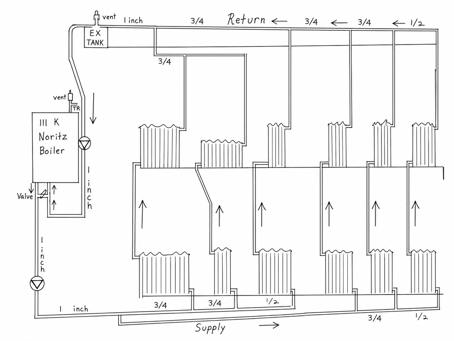
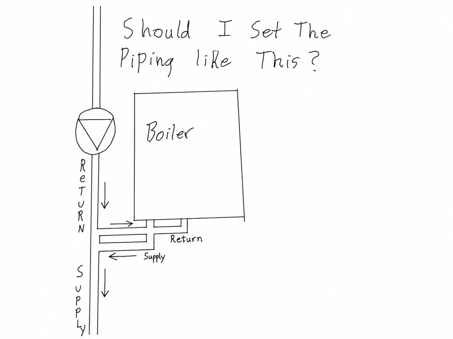
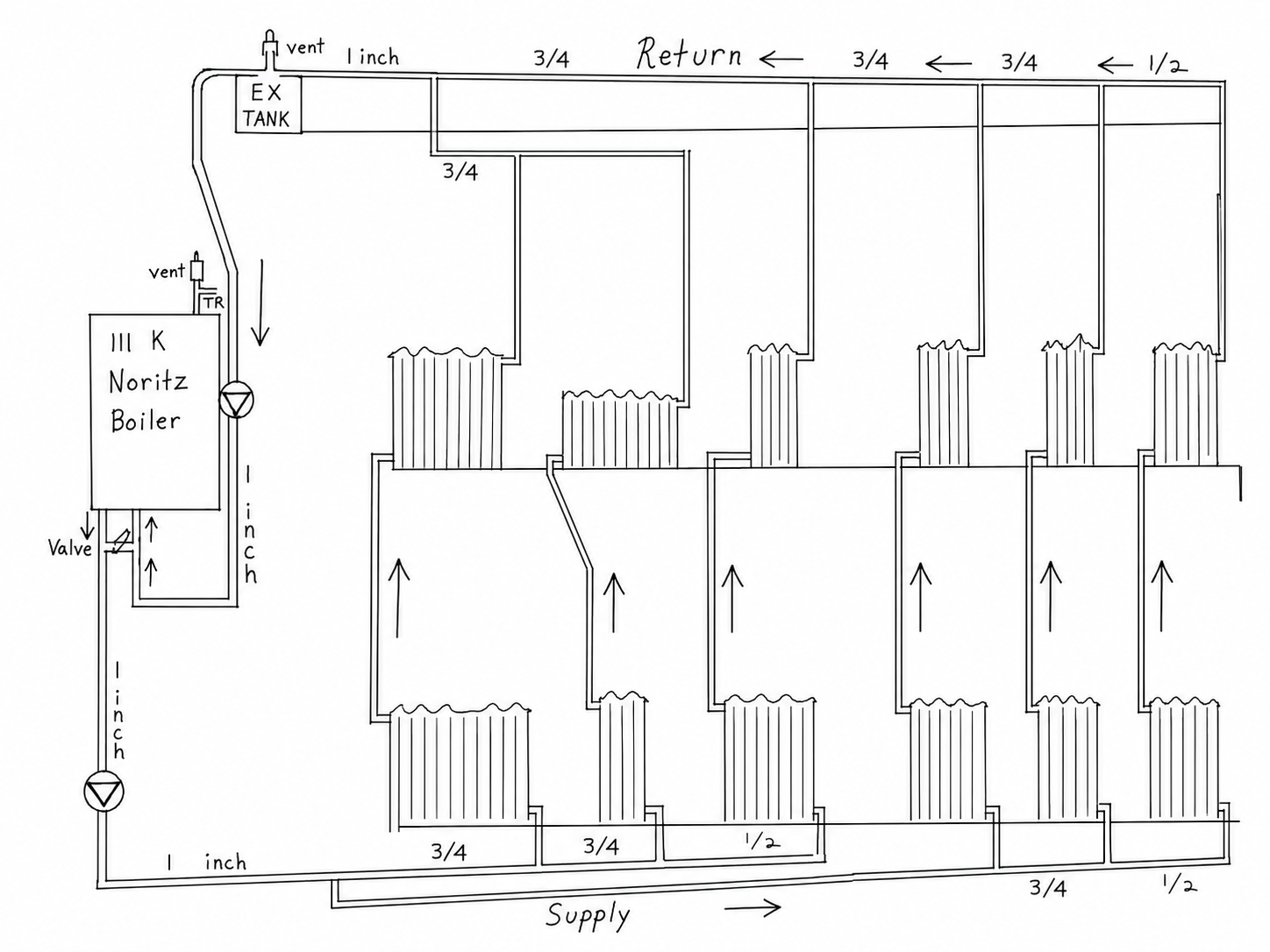
I have included a new diagram more true to how it is set up in real life.
With the "bypass" valve open, the boiler short cycles immediately. The supply water goes directly back into the boiler, it thinks the system is hot and the burner turns down.
With The bypass valve closed, it forces all water through the boiler and it heats properly, but causes a flow issue as the boiler can only move so many GPM.
 0
0 -
if the boiler short cycles when the bypass is open either the system pump isn't moving much water on its own or the boiler circulator isn't working. though it isn't really quite p/s it should act more or less that way with the bypass open. probably the first thing to do is to do the math on the external circulator. also make sure the controls are set up right to run the external circulator on a dh call however that is set up.
some pictures of exactly what is there would help too because the sketch is simplified and may be missing something important.
what kind of emitters are these? are they standing cast iron radiators or are they something more restrictive?
0 -
You have to go back to the basics.
You know the EDR, so you know the btu output of the radiators. Since you know the total radiation load you divide that # (600edr x 150)= 90,000/10000=9gpm. I would go slightly larger like 10-11 gpm. this is for the heating loop.
Change the piping to primary secondary
Then the secondary pump need to move 10 gpm against the resistance of the piping and the radiators.
So you need to calculate the pip resistance.
The simplified method (which I don't like) is to take the longest run of pipe from the boiler to the radiation and back to the boiler and find the pipe length of the total run and look up the resistance to flow. We can help with that.
Then you size the pump at 10gpm @ X# of feet of head (which you get from the calculation)
0 -
there are likely multiple problems now.
i don't like the opening the bypass makes the boiler unable to distribute its heat energy. either one of the 2 circulators sn't running or is air bound or if the resistance of the system is great it takes a combination of the head of both circulators to move enough water. that is unlikely unless the emitters are very restrictive.
but that isn't the original problem i don't think, it is a problem created trying to fix the initial problem
0 -
I think the issue is your system pump is not working. When you close the bypass, you are now using the boiler pump to push through the system that is why you get heat.
If that bypass is big enough (~1 1/4" ball valve), it can work as a PS loop. Not ideal, but not enough to re-plumb the whole setup.
With a working and correctly sized secondary pump, you should get proper heat with the bypass fully open.
0 -
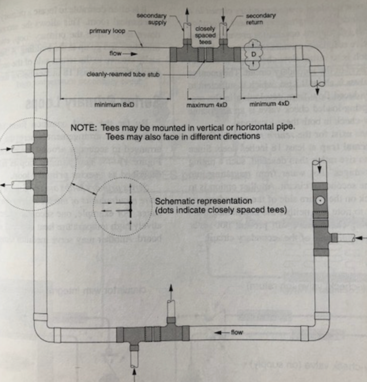
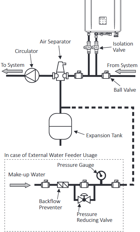
If you are going to go to the trouble of re-piping the closely spaced Tees do it like the manual shows, not like your sketch.
National - U.S. Gas Boiler 45+ Years Old
Steam 300 SQ. FT. - EDR 347
One Pipe System0 -
You do not have a primary secondary piping unless there is a header inside the boiler. Their piping diagram seems to indicate that the installer provides the separation.
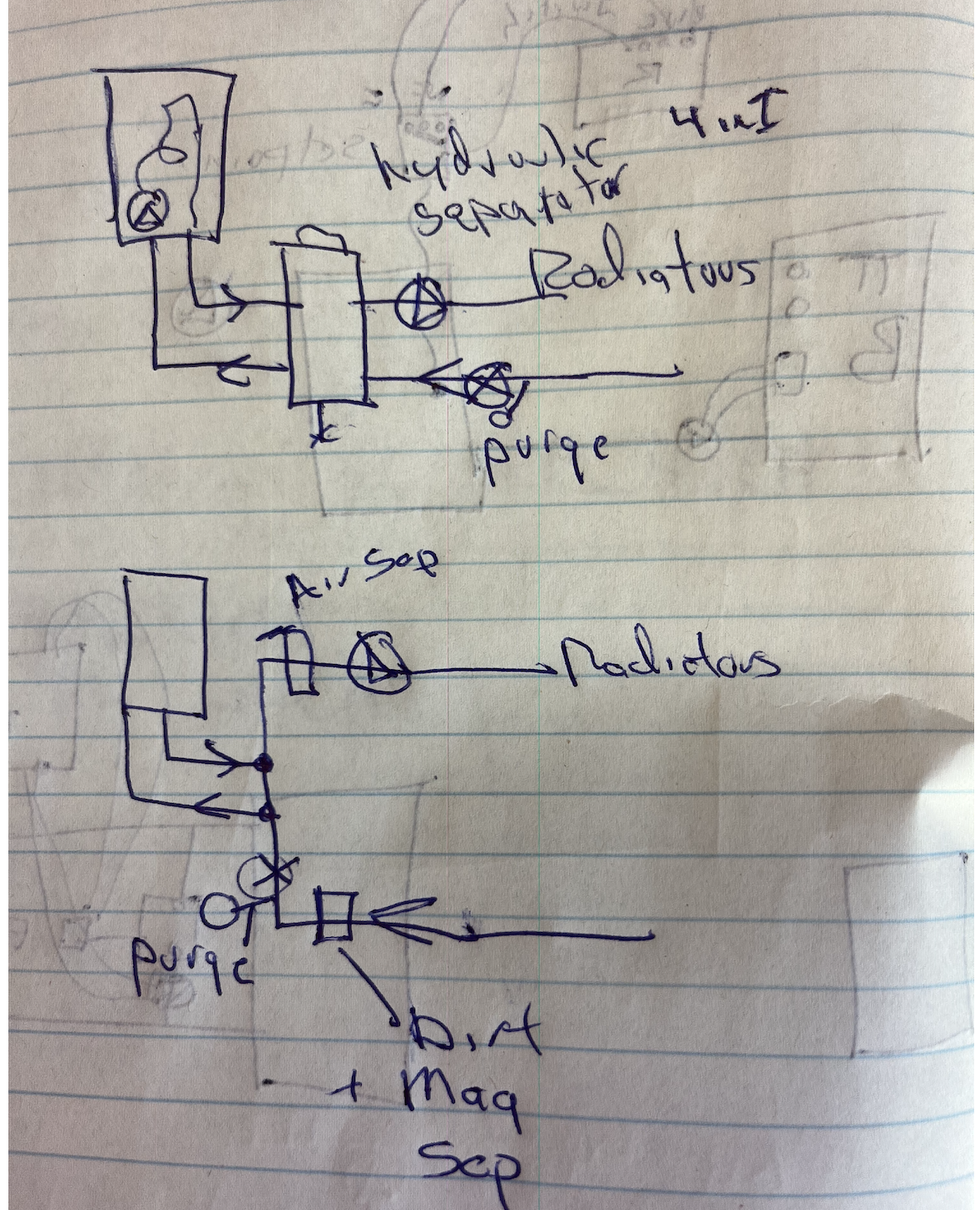
Closely spaced tees is the simplest way. I prefer a hydraulic separator to accomplish 4 things
here are two options.
You want the air purger on the hot side of the system, not return.
Do the radiators have hand wheel valves to balance each one?
 Bob "hot rod" Rohr
trainer for Caleffi NA
Living the hydronic dream0 -
while the boiler piping isn't great, it isn't the problem either. the fact that is short cycles if the "bypass" is open means either one of the circulators isn't working or is very undersized, the system is very high resistance, or it isn't actually piped the way it is drawn. figure that out first then work on better near boiler piping.
0 -
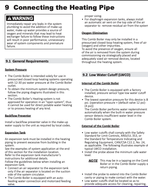
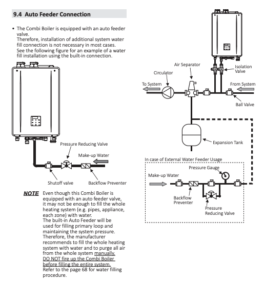
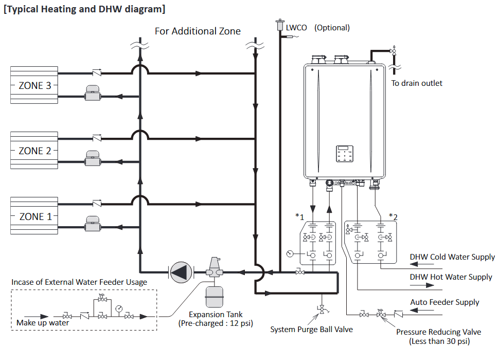
Sadly, not much piping info in their manual. i don't see any direct pipe examples?
Looks like a tankless heater that morphed into a boiler.
With the bypass closed you have the system and boiler pump in series, which doubles head, so that should provide plenty of flow.
I wonder that there is a filter or strainer inside the boiler somewhere reducing flow through the boiler HX. Or the valve that toggles from heat to DHW hx flow not opening completely.
Here are guidelines form proper P/S piping. I would avoid any valve between the close tees, there is no need for it and it can cause enough pressure drop to induce unwanted flow..
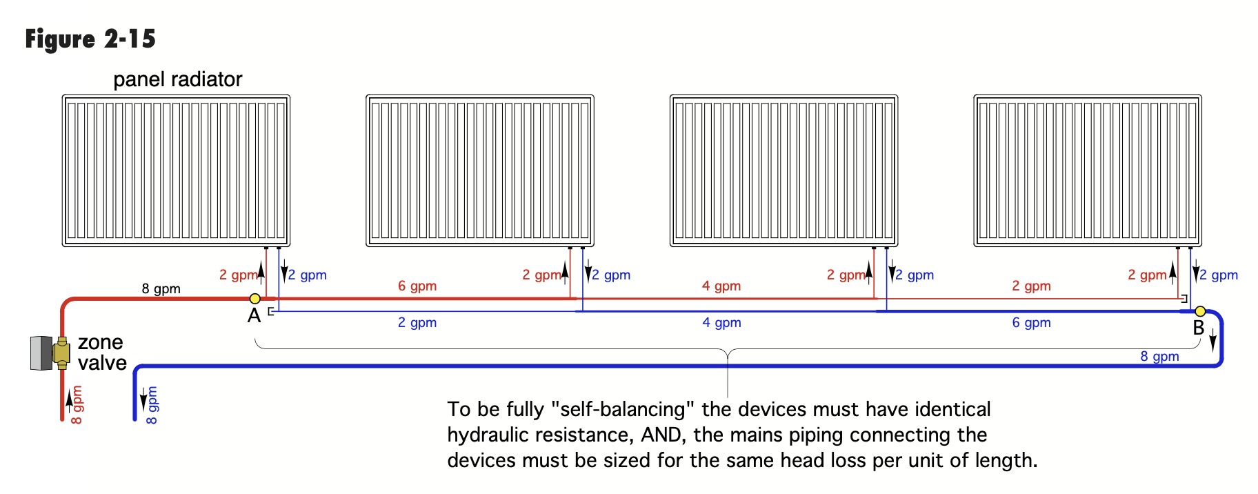
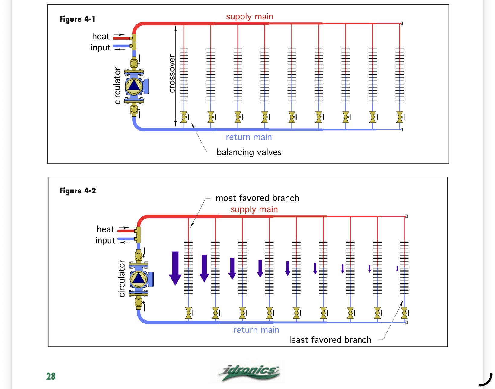
I'm not clear on your actual piping, but in either case the closest radiators to the boiler will get most of the flow without balancing or reverse return piping. It's the path of least resistance.
An example of reverse return piping. The first rad supplied is the last returned so the system basically self balances. Valves at each radiator can get you a fairly balanced system, assuming it is a single zone.
 Bob "hot rod" Rohr
trainer for Caleffi NA
Living the hydronic dream0 -
I went through the boiler manual pretty good.
The lowest TD this boiler will work at is 30 deg TD with 11 gpm of flow. They say 11 gpm is the max flow through the boiler.
The pump curve for the internal pump shows a max flow of 4.5 gpm @0' of head and 0 gpm @11' of head. This does not seem to match up
That pump curve I am not understanding
But I am confidant in saying that the secondary heating loop needs to have a proper primary secondary connection and the secondary loop needs to have a circ that is sized correctly if this is to have any chance of working.
0 -
P/S piping of some sort, preferably a hydraulic separator, TRVs on each radiator, with a Grundfos Alpha on the system side.
Steve Minnich 1
1 -
"They say 11 gpm" does that include or exclude the DHW flow ?
Not a pump guy but "max flow of 4.5 gpm @0' of head and 0 gpm @11' of head"
Why couldn't a pump do 4.5 gpm with no head pressure and at a head pressure of 11' it will no longer move anything significant. Kind of stating either end of the curve.
Also we don't even know if the valve is a full port ball valve or something else, and if the pipe size also is 1".
Seems as stated earlier multiple issues promotes poor performance.
National - U.S. Gas Boiler 45+ Years Old
Steam 300 SQ. FT. - EDR 347
One Pipe System0 -
because of the stacked series radiators TRVs would be tough.
0 -
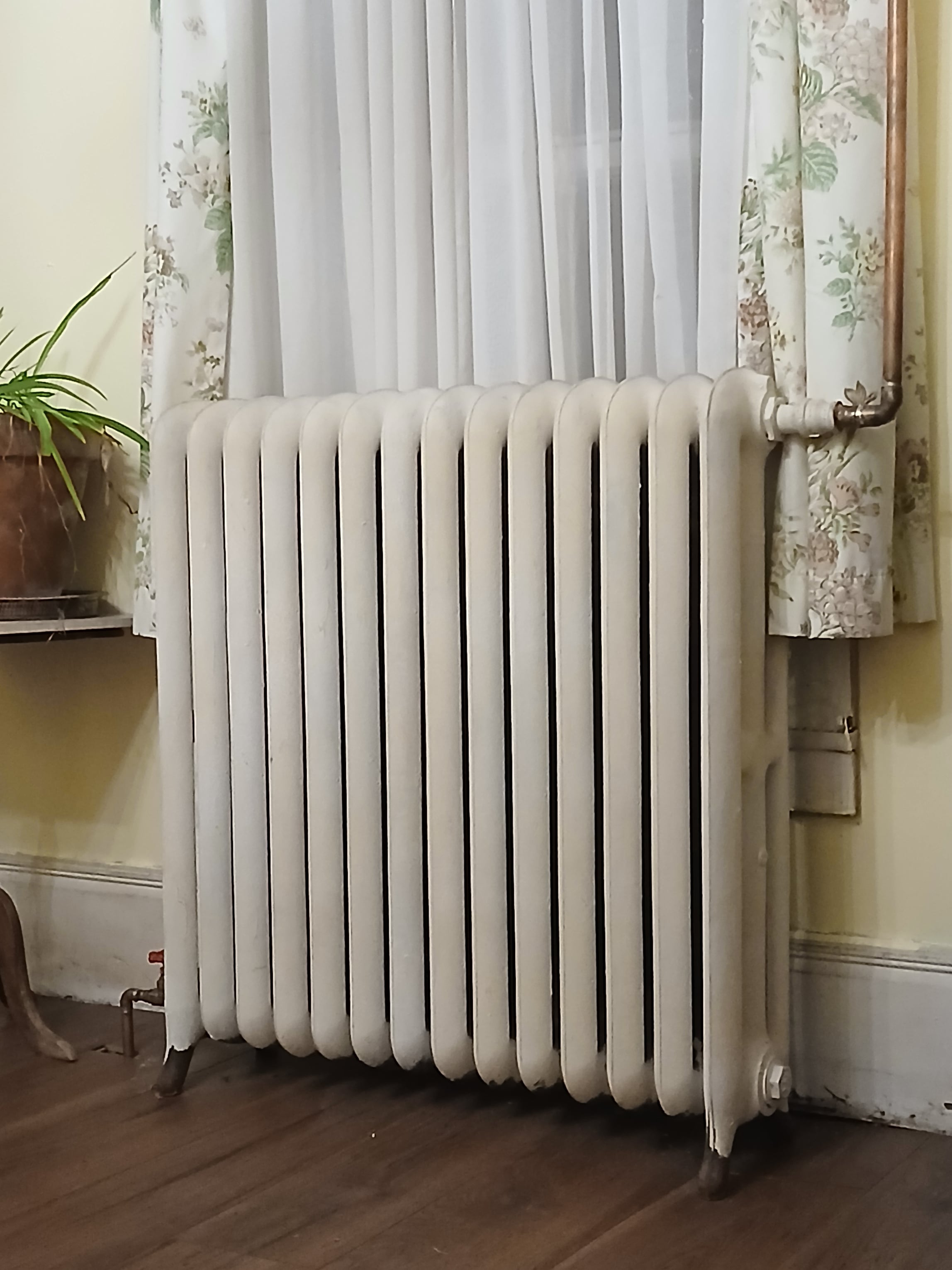
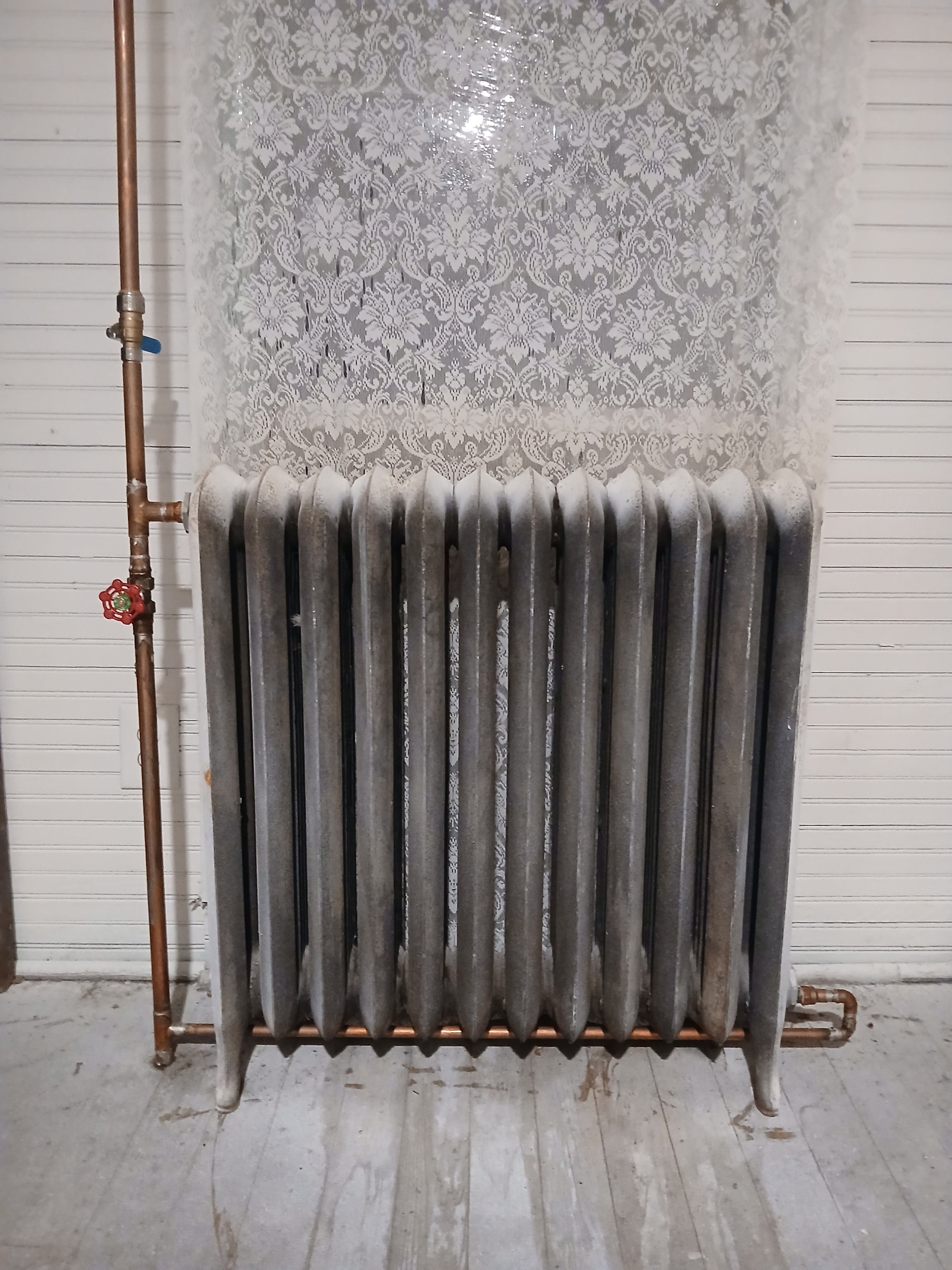
I appreciate all of your knowledge and help.
The longest run is 200 feet. It goes through progressively smaller pipe. The last third of it is 1/2 inch copper. It has 11 elbows on the way there and back. Piping P/S would eliminate 2 of those elbows. Ive tried to calculate head, but im not sure.
Each radiator has a gate valve on it. The ones closest to the boiler are almost closed, and the furthest wide open. The ones in the middle open about 1/4 of the way.
Each radiator has one directly above it on the second story. The second story radiators have a bypass pipe that can be opened or closed to throttle it independently of the radiator below it.
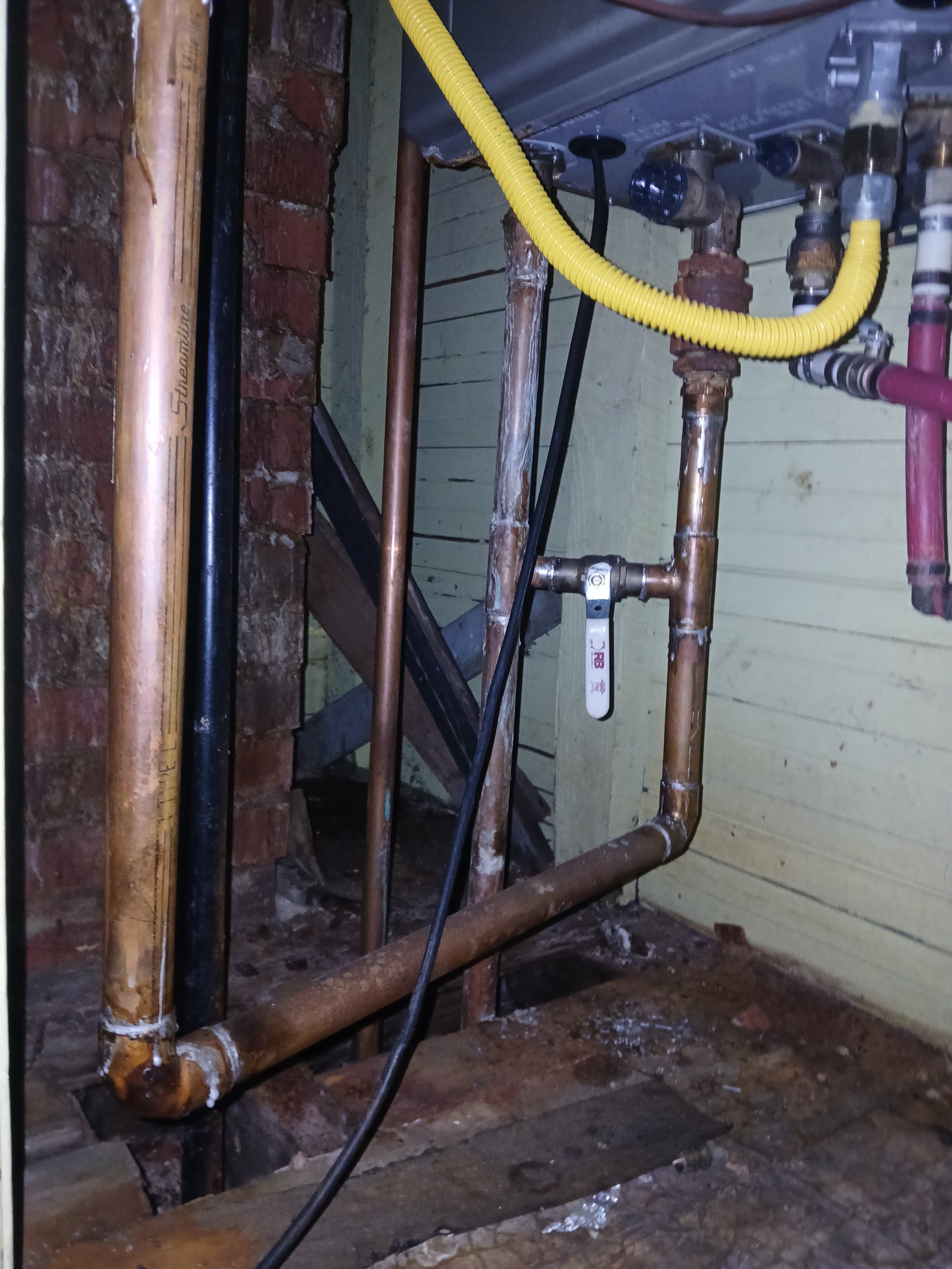
The bypass at the boiler is 3/4 and the boiler piping is one inch.
The pump is a "wisewater " 3 speed pump. I cant find a curve for it, but it says 24 feet of head. No GPM listed that I can find.
It seems to me from the knowledge here, that it needs to be piped P/S and a properly sized pump. Nothing else seems obvious. Does it matter if supply is upfeed or downfeed?
0 -
Are there 3 pumps on this system? One inside the boiler and two additional as shown in your drawing?
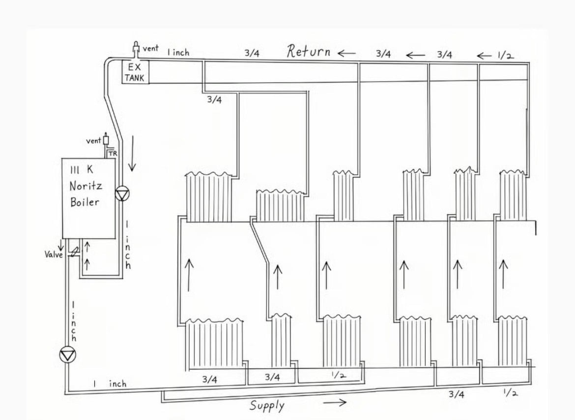
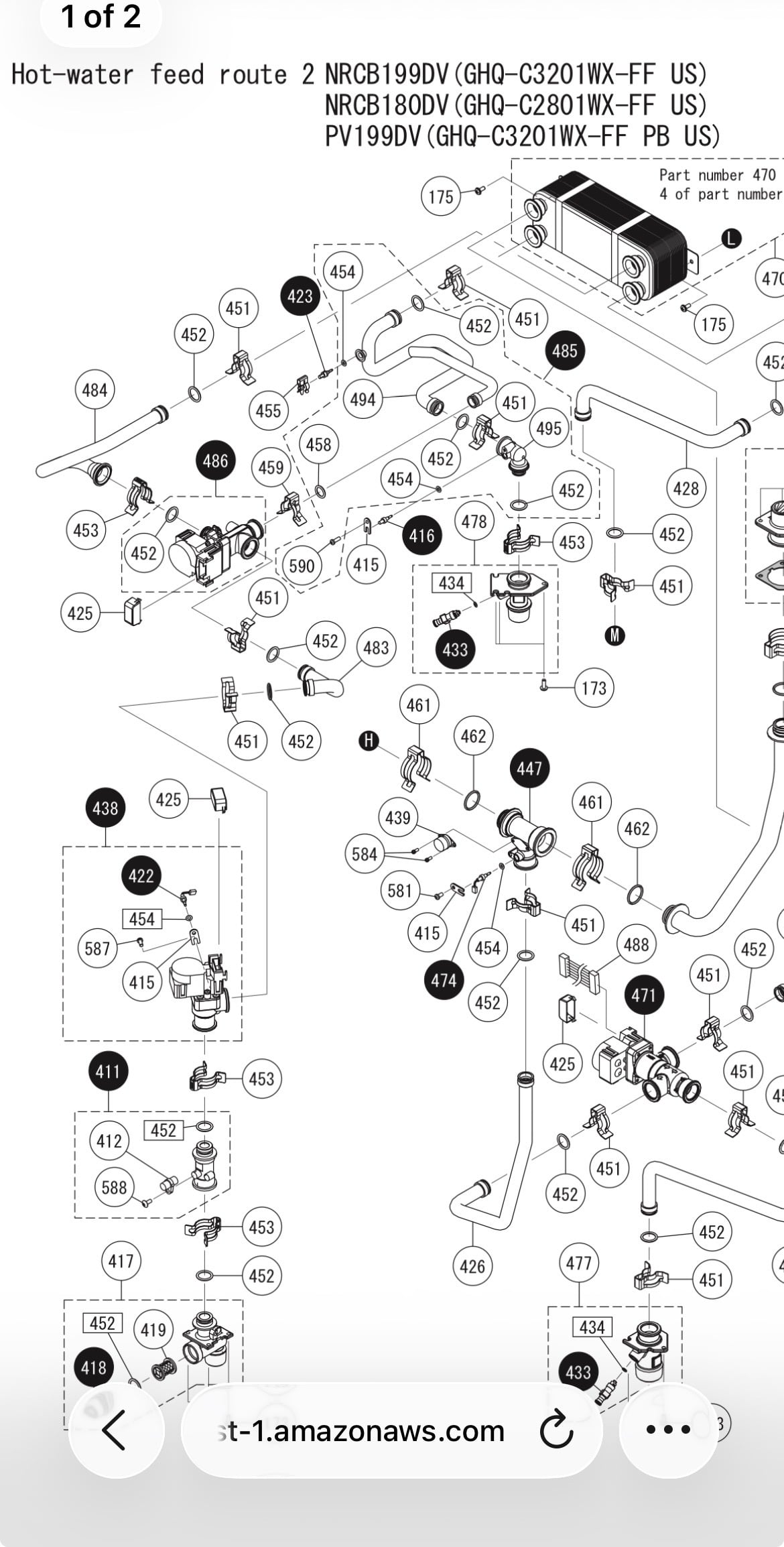
Inside the boiler is a diverter valve 486, it may be stuck and not allowing adequate flow through the heat circuit. It toggles between dhw and heat functions
475 is the internal pump, it could be seized and not flowing the boiler at all?
Either or both of these could cause the boiler to short cycle, over heat
 Bob "hot rod" Rohr
trainer for Caleffi NA
Living the hydronic dream0 -
gate valves should not be used for balancing. the gat being partially open with flow will cause the gate to chatter and damage the screw that drives the gate up and down and it may erode the sealing surfaces of the gate. it should work in the short term though. globe valves or ball valves should be used for balancing.
which radiators don't heat? the way it is set up with all the flow through the lower radiators and only a bypass on the upper radiators, the amount of water needed to move the needed heat may only flow in to the lower radiators and dump all the heat there, by the time the water gets to the upper radiators it is cold.
since the piping is all open I would be inclined to tee each supply and each return connection from the main and connect separate supplies and returns to each radiator with either a globe valve or a radiator valve for each radiator. that being said, unless it is the radiators without the bypass that are the only radiators heating, it could be fixed by fiddling with the valves.
you need to sort out the circulator problem, one of them isn't running and you need to figure out which one and why.
oh, and it doesn't matter if the supply is top or bottom but air will want to move up so supply below and return above is easier to get the air out of.
0 -
489 and 420 are filters. Typically on the dhw, but I would check them also
Bob "hot rod" Rohr
trainer for Caleffi NA
Living the hydronic dream1 -
while neither a gate valve or ball valve are ideal for balancing, They can work. The ball valve will have the most effect at the last 20% and be very sensitive to small movements.
However with manual balance valves when you make a change to one, all the others in the system are changed and need to be readjusted. So it will be a tedious process.
Ideally the valve would have test ports to connect a delta p meter to set and adjust each one to the required flow
But you have some flow issues to sort out first.
 Bob "hot rod" Rohr
trainer for Caleffi NA
Living the hydronic dream0 -
Speaking as a homeowner,
It seems obvious to me that this heating system was a using a coal fired gravity fed hot water boiler system with larger steel pipe at one time.
Changing the system back to an open to air expansion tank with gravity fed system would simplify this issue as the piping runs seem to favor of a gravity fed hot water system.
1 -
Seems pretty obvious that this is not piped right. The rad in the picture does not match the drawing. Looks monoflow with the valve doing the job of the venturi tee.
I see a lot of pipe and long runs of 1/2" pipe and a lot of 90 degree elbows making a lot of head that the circ can't overcome
This is all about flow and not having enough of it. looks like someone threw it together without any calculations at all hoping it will work.
You can't fix it with band aids it needs a complete redesign to find out if any of the existing piping can stay
Sounds like the boiler, radiation and heat load match up pretty well so that is a good thing
2 -
If I was water I would be lazy and go where its easiest to go. so of course your rads on the 1/2" are struggling. If I was a hack contractor I would try to solve the problem by adding more pumps to the system, all they accomplished is eliminating any point of no pressure change. without primary/secondary piping (properly done, not just random tees and call it a day) the external pumps will fight with the diverting valve inside the boiler. its a hack job through and through. you need to repipe it or accept it's not going to work correctly.
0




Categories
- All Categories
- 87.8K THE MAIN WALL
- 3.3K A-C, Heat Pumps & Refrigeration
- 60 Biomass
- 430 Carbon Monoxide Awareness
- 133 Chimneys & Flues
- 2.2K Domestic Hot Water
- 6K Gas Heating
- 124 Geothermal
- 170 Indoor-Air Quality
- 3.9K Oil Heating
- 79 Pipe Deterioration
- 1.1K Plumbing
- 6.7K Radiant Heating
- 397 Solar
- 16.1K Strictly Steam
- 3.5K Thermostats and Controls
- 56 Water Quality
- 51 Industry Classes
- 51 Job Opportunities
- 18 Recall Announcements