Burnham ES2 IQ Panel Question

I have a Burnham ES2 boiler with an IQ panel but I have no options installed.
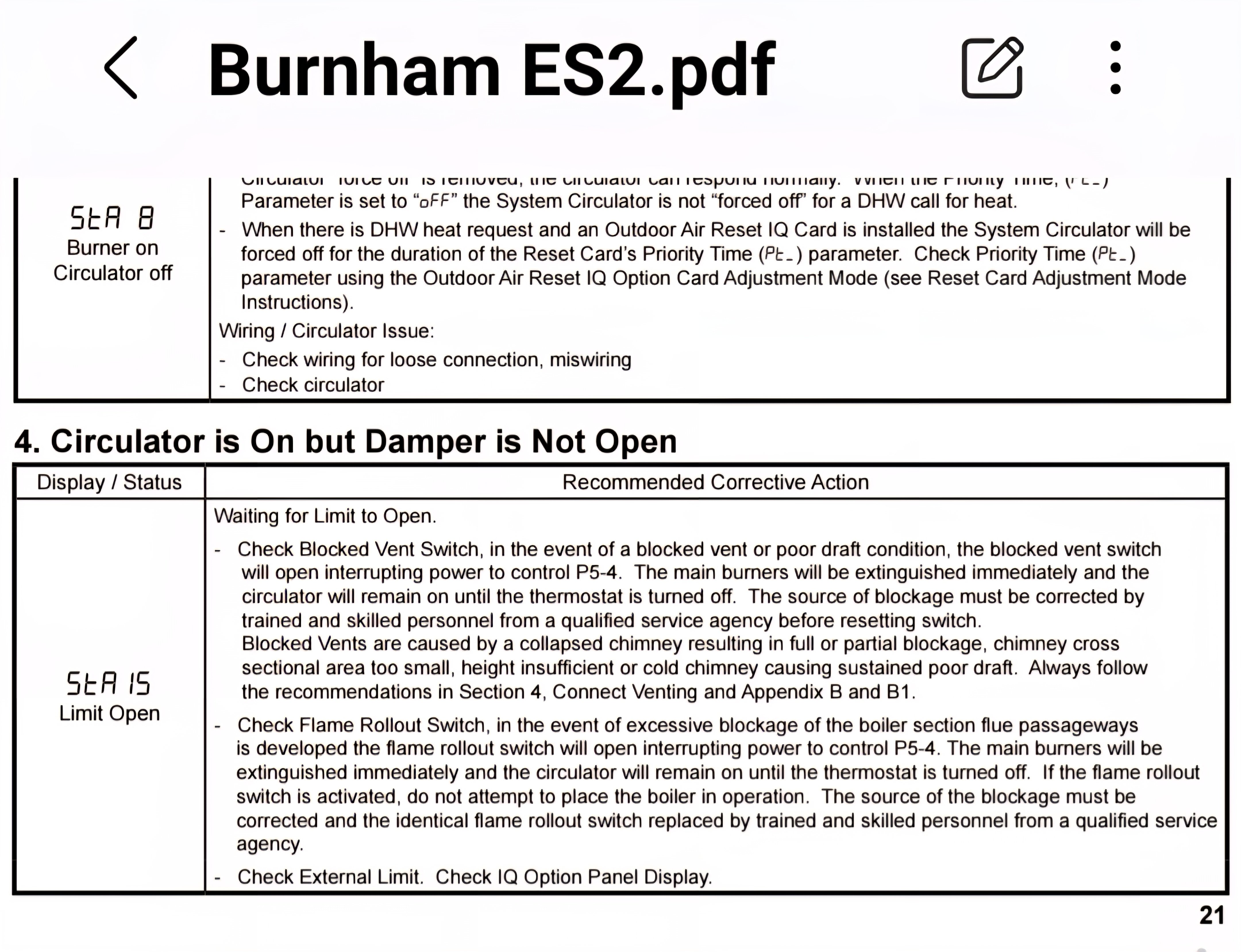
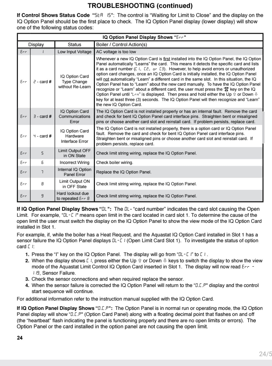
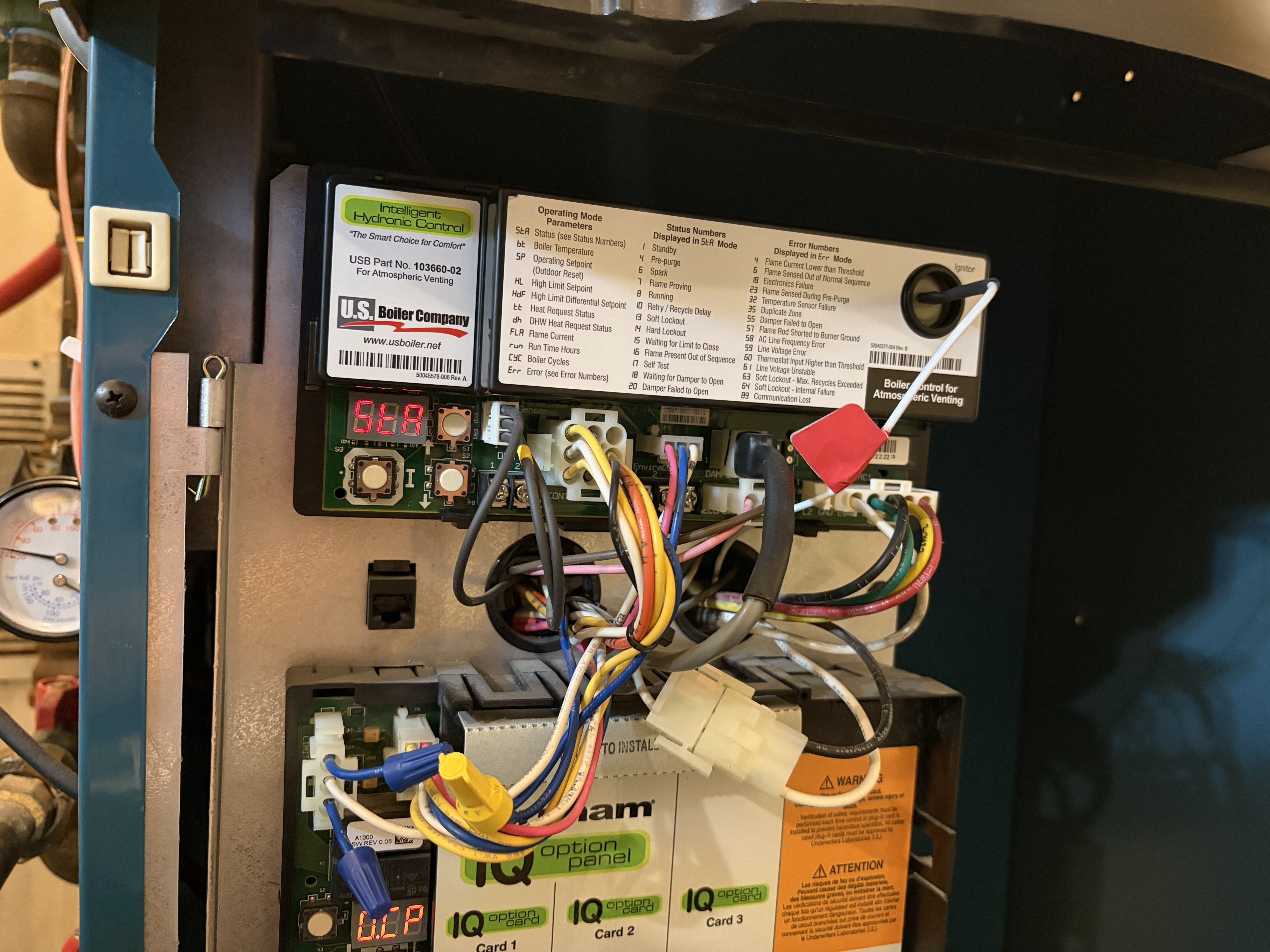
I just had a problem where the boiler wouldn't fire - Status 15 and Error 5 on the IQ panel.
I have a service contract with my gas utility so someone came and fixed the issue by cutting the two blue wires and connecting them together. He said this bypasses the limit that was causing the error. He said this fix is provided by Burnham and since I have no IQ options installed, I don't actually need the IQ panel at all.
In fact, he said that boiler came two ways - with and without the IQ panel. Mine happens to have it installed from the factory though it's not being used.
He said this fix will permanently prevent that Err 5 from happening again, which he said is quite common but he didn't replace the board.
Here's my question. Could the IQ panel fail again in the future with some other error? And is the IQ Panel really not needed?
If my boiler doesn't really need that panel, is it possible to eliminate it if it should fail again in some other way in the future?
I asked the service guy and he didn't know but he said he'd imagine you could put other wires together to just cut out the panel entirely but he didn't know which pairs to connect.
So I want to know for the future should this panel fail again with some other error.
Can the panel be bypassed entirely and how would it be done? Which wires need to jumped to make that happen?
I know that some people will say to just replace the board if it fails, but I'm thinking that if it's not needed and not being used, it's better to just eliminate a point-of-failure from the mix.
Thoughts?
Comments
-
Can you post a pic of the blue wires and where they go?
I'm not too familiar with those boilers, but how was there an error 5 if there are no cards?
0 -
Error 5 is not associated with any specific card, @HVACNUT .
I installed a Crown Boiler with that same system and chose to use both the LWCO card and the ODR card. After spending nearly two weeks trying to get that setup to operate reliably, it was nothing but trouble.
In the end, I disconnected the entire IQ system and bypassed all of the IQ panel limits so the boiler was essentially wired as if the IQ system had never been installed in the first place. It took me about two hours to rewire everything.
I ultimately had to give the customer a discount for all the additional trouble because there was no outdoor reset functionality afterward, even though the customer had paid extra for that feature.
Not a fan.
Edward Young Retired
After you make that expensive repair and you still have the same problem, What will you check next?
 1
1 -
is this user error or is this the chrysler problem? was something not installed right because they didn't tell you, or would it have been a great idea if it worked, if they had accounted for what was going to happen when they put it out in the real worked?
0 -
OK, but I assume the boiler here has been in operation for some time. If the tech bypassed something in the options card area, shouldn't that have already been done? It wouldn't always have shown "sta 15", and "err 5" ? How did it ever run? I'd like to know which Blue wires were spliced through.
0 -
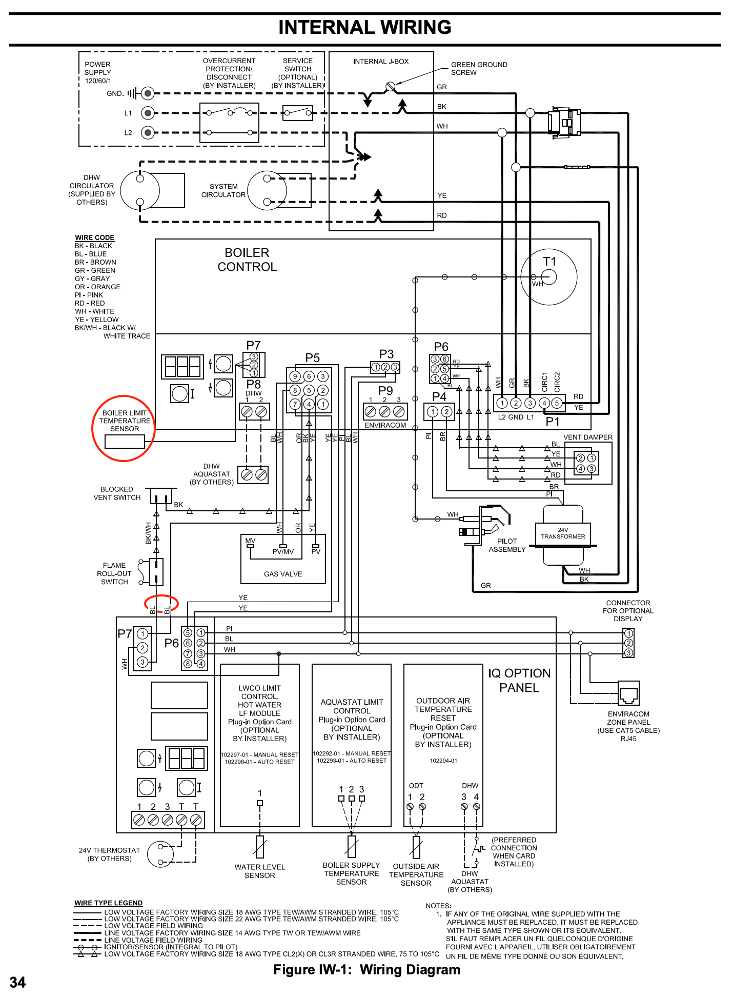
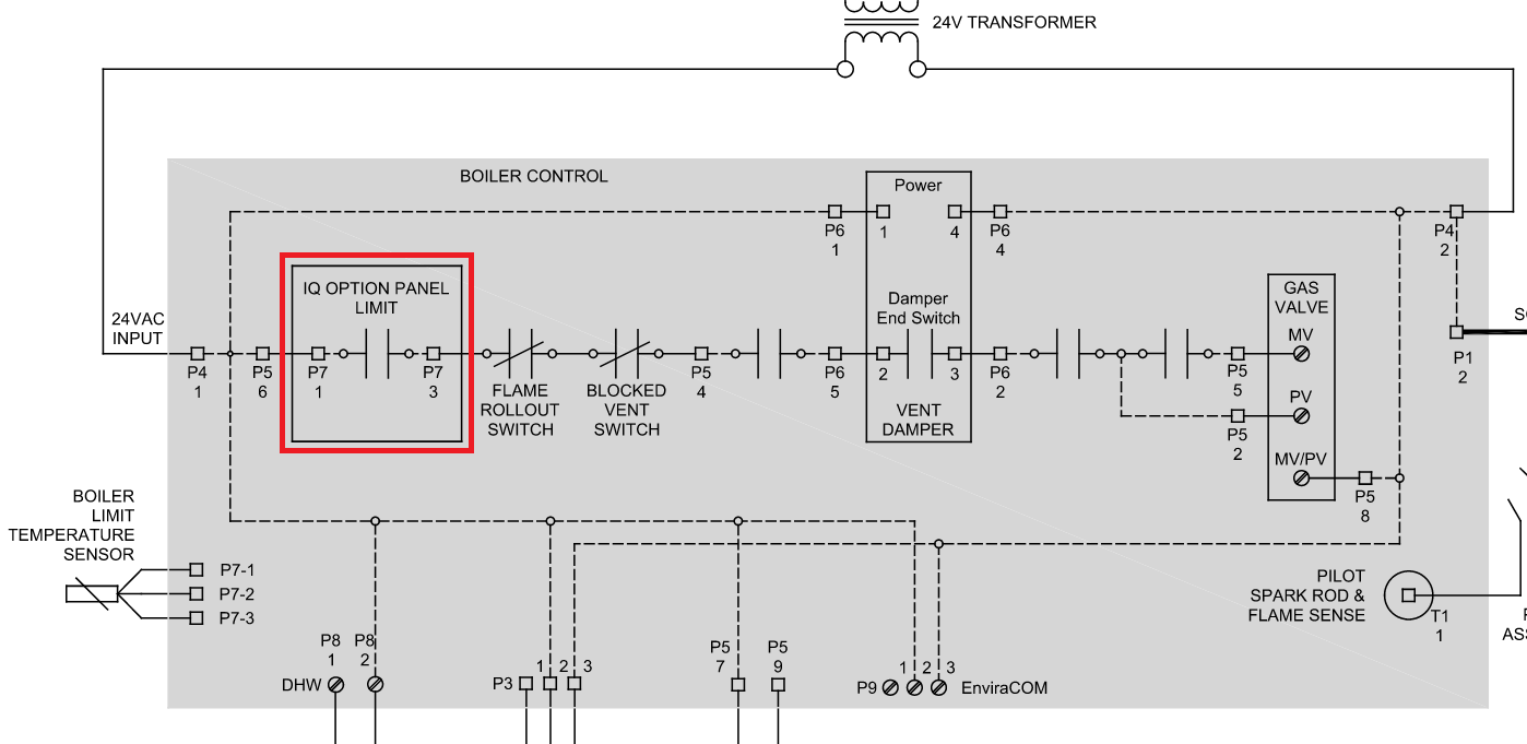
As I recall from my one unplesant experience with this control, I believe there is a limit circuit that includes the flame rollout switch and blocked vent switch that is in series woth the blue wires that come from the IQ panel. if the aux limit, LWCO or the ODR feature requires the burner to stop those blue wires interrupt the limit circuit. If there are no cards in the IQ panel, then the blue wires are not needed to open that circuit since there is nothing to open. The fact that the IQ panel can still malfunction and open those blue wires in the circuit is probably part of the problem with the whole idea. I don't believe there is any new euipment since that time that offer this IQ system
As you can see the Boiler Control still has a high limit sensor incorporated in the system, so that "jumping" or "shorting" (I believe shorting is the incorrect term however others use that term for this procedure) the IQ panel's blue wires do not affect the unit's safe operation. (See Red ovals)
Edward Young Retired
After you make that expensive repair and you still have the same problem, What will you check next?
0 -
This boiler has been in service for over 13 years. I have the IQ Panel installed but there are no options installed. The service tech said since I have no options installed, the IQ system isn't needed in my case. I have a separate low water cutoff that's not part of the IQ system.
So that got me thinking that if it's not needed and is just another (expensive) point-of-failure, then why not just eliminate it entirely if it fails again. Hence my original post. Is it really not needed in my case and what's involved in eliminating it?
Here are the pictures requested by @HVACNUT
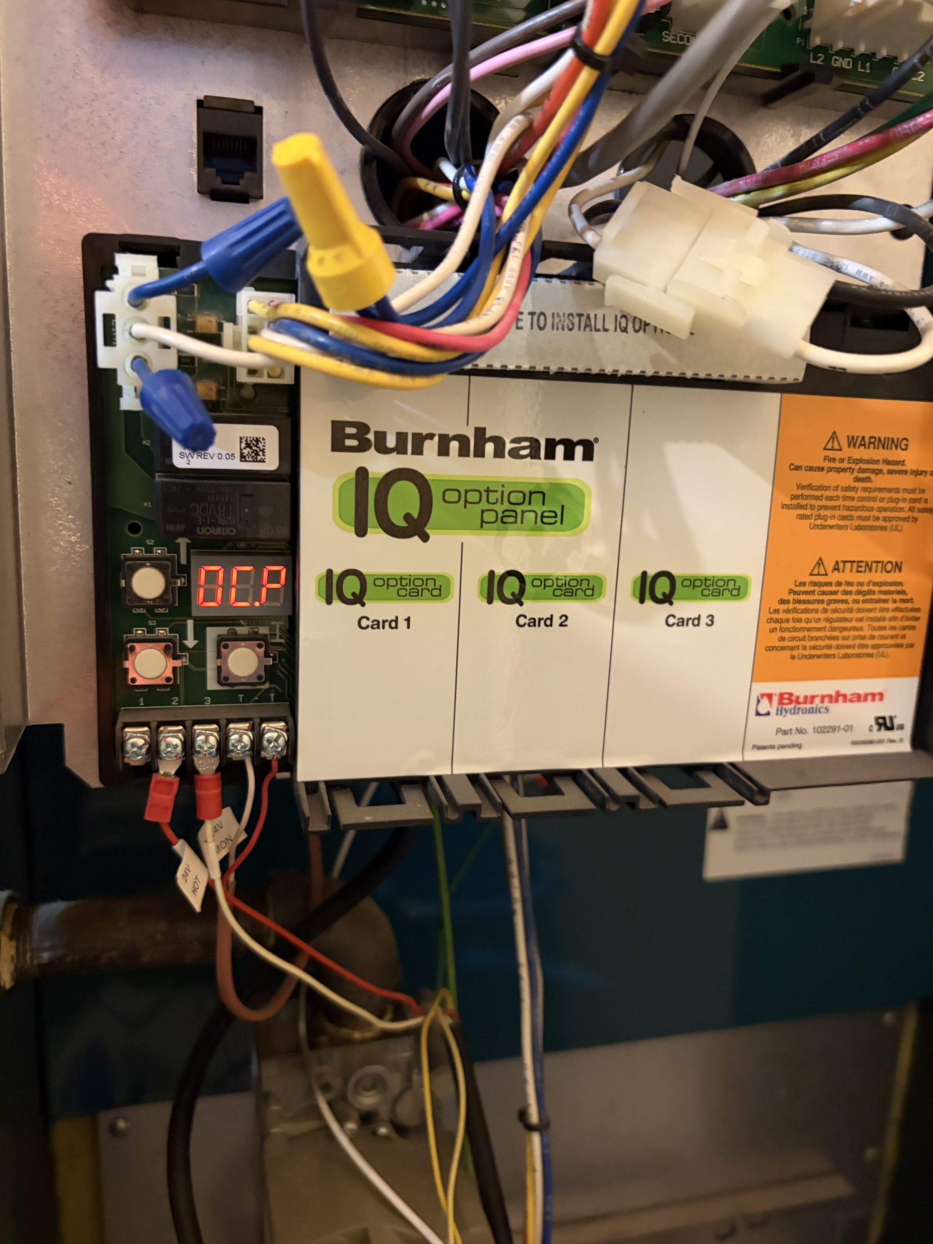
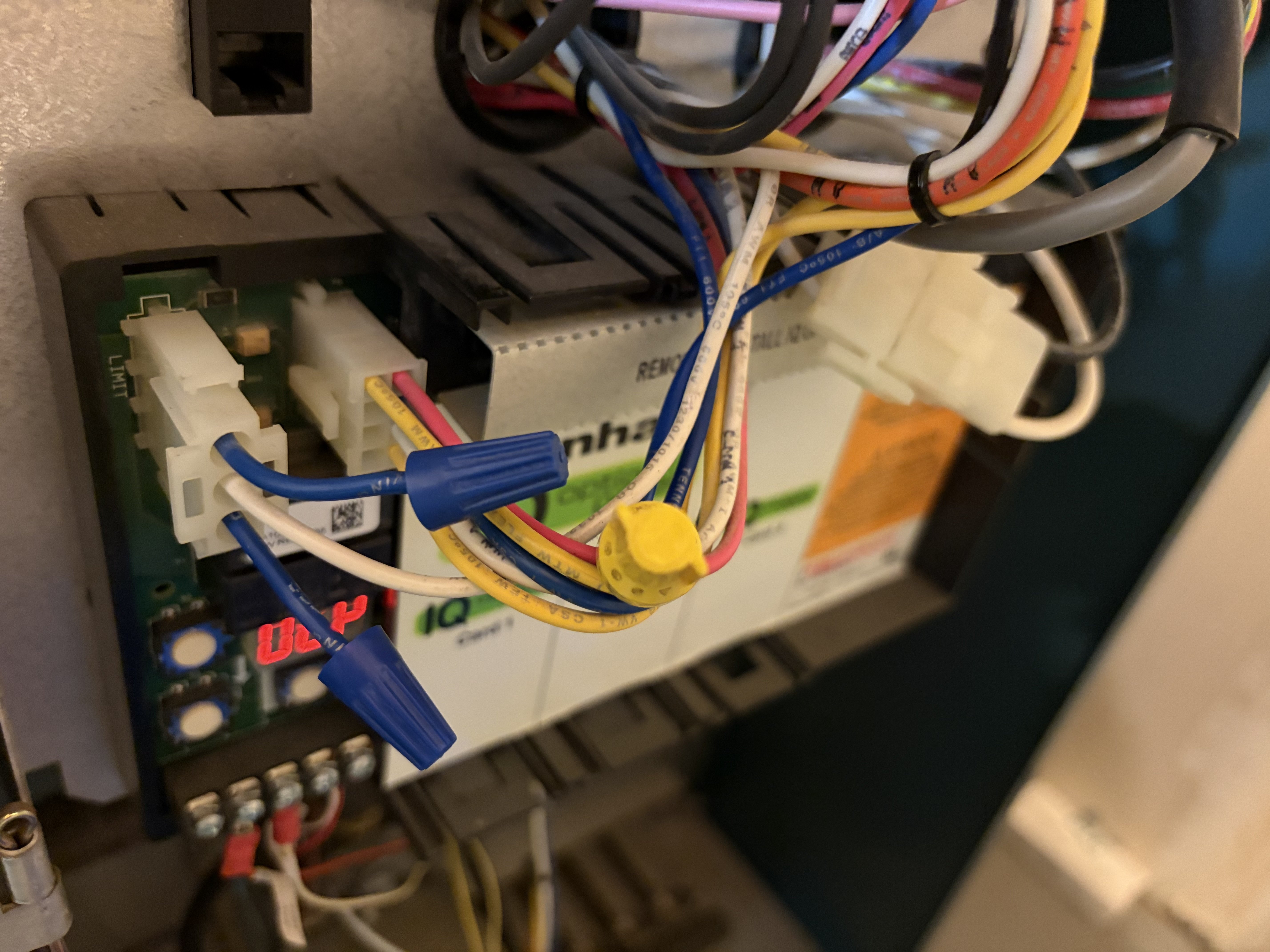
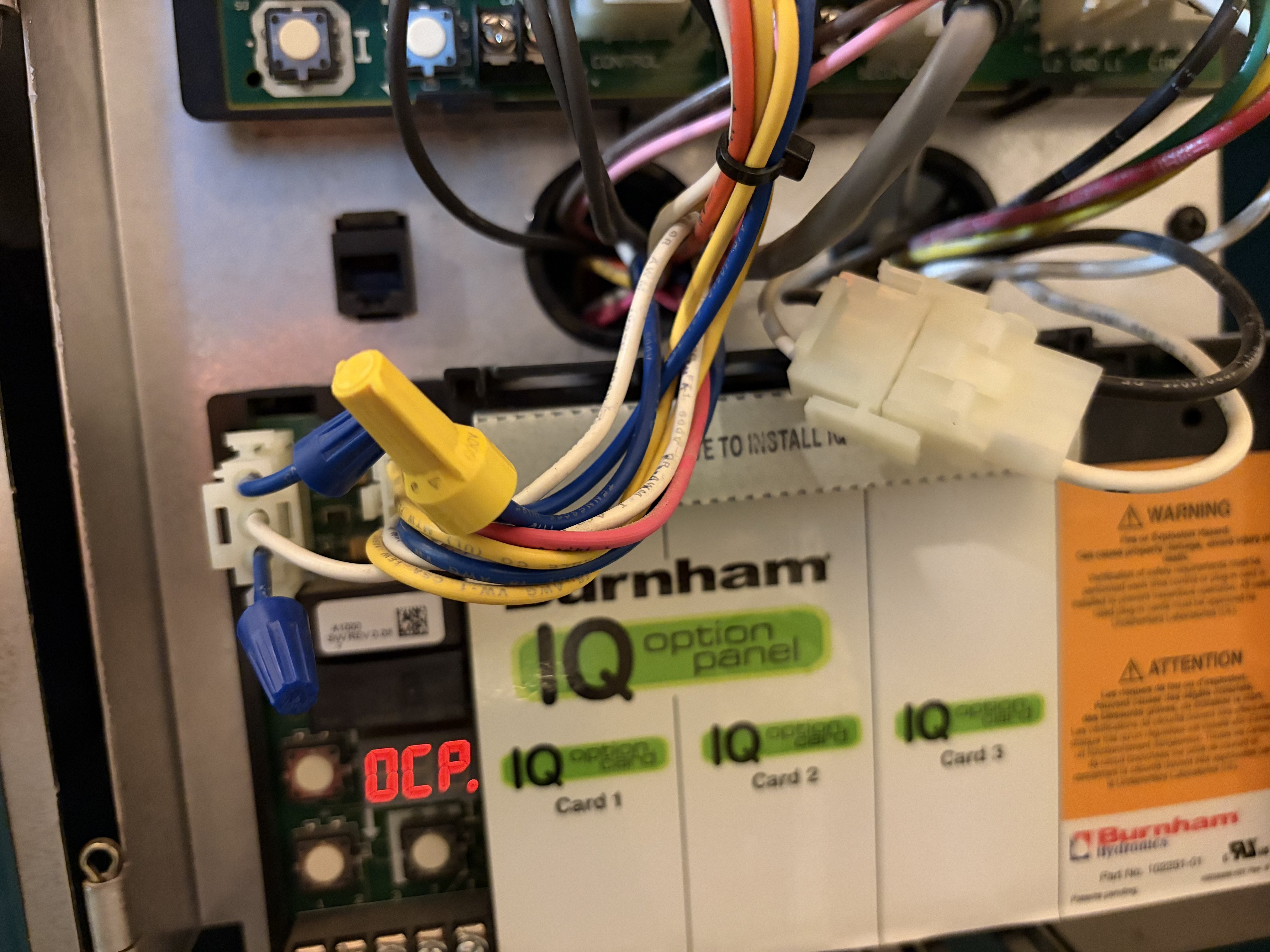 1
1 -
It looks ok. Its just weird that after 13 years it needed to be done. If there's no option limit card, it must be internally jumped. But now its not?
As long as everything works the way it should, the circuit with the blue wires is complete. 24 volts goes from the transformer into P4/1, out of P5/6, and that starts the blue wires safety circuit that continues through the vent damper end switch, then to the gas valve. All safe. Just strange.
0 -
Well, the boiler wouldn't fire up because of Err 5, so instead of replacing the board, he just jumped those wires and now it's working fine (as much as I can tell). I have notes that a board was replaced 3 years ago but I'm not sure if it was the IQ Panel or the main control board above it. My notes say IQ but I think it may have actually been the main board. Not sure.
Two things though:
- I hear a faint beeping from the IQ Panel. Can that be reset and should I care? It's showing no errors and the boiler is in a room where that beeping can barely be heard. But does the beeping signal that there's still a problem I should care about?
- Could the IQ Panel still fail and shut down the boiler? Or did jumping the blue wires take care of that never being a problem in the future?
0 - I hear a faint beeping from the IQ Panel. Can that be reset and should I care? It's showing no errors and the boiler is in a room where that beeping can barely be heard. But does the beeping signal that there's still a problem I should care about?
-
is it beeping or is it more like a squealing sound? if one of the power supplies on it failed it could make a sound like that.
it looks like you could probably just unplug everything from the iq board and it would work without it as long as the blue wires are jumped. would have been nicer to do it at the molex connector instead of cutting wires.
0 -
Here's the sound.
So are you saying the IQ board is already effectively disconnected just by the blue wires being jumped?
0 -
Looking a little more closely, it looks like the thermostat comes in to the iq control and the only connection back to the boiler control board is a serial bus and the safety contacts so it looks like it has to be there because it looks like the heat call is being generated on the serial bus.
i think the 2 yellows are 24vac to power the iq board.
0 -
So back to my original question.
Is there a way to put wires together to eliminate the board?
From what I was told, not all ES2 models have IQ so there must be a way for it to all work without it.
I'm planning for the next no-heat / no-hot-water emergency and just want to know beforehand what the options are. As I said before, if IQ isn't really needed in my case, I'd rather eliminate it than replace it.
0 -
Sounds like an alarm clock. An annoying alarm clock. Are you positive the sound is coming from the boiler? I don't think the ES2 has an audible alarm.
0 -
you'd have to find an installation manual for one of those boilers and reverse engineer it. there are 3 possibilities that I see:
- The non IQ version uses a different boiler control board with thermostat terminals..
- Some of the unused pins on that molex connector for the IQ bard are RW/TT/XX and C for the thermostat.
- There is a small serial board that has the thermostat terminals and a UART for the serial bus that plugs in to the connector for the IQ board.
0 -
Definitely. I put my the ear to the IQ board. I put the mic on my phone to the IQ board to record that clip.
0 -
OK. I found this - https://s3-us-west-2.amazonaws.com/catsy.782/ES2+IO+Manual.pdf
I have a question. Please keep in mind I am neither a plumber nor an electrical engineer but I think I'm taking a stab at understanding this.
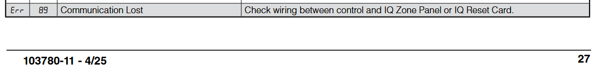
Looking at page 40 in the IO manual, it looks like the wires coming into the IQ board on terminals 2 and 3 (the 2 wires on the left) can be moved to the EnviraCOM terminals on the main control board. Following the wiring diagram, I think this is where they connect to internally.
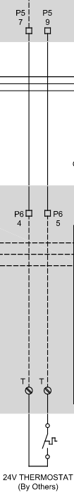
Then the two 24V thermostat wires on the right (both labeled as T) would be spliced into the wires going into positions 9 and 7 (top and bottom left) of the P5 connector.
Am I understanding this correctly? Would doing that remove the IQ board from the mix without breaking anything?
0 -
I'll ask another question. Is replacing the IQ board plug-and-play?
That is
- shutting off the boiler
- disconnecting the two connectors and the thermostat wires
- removing the old board and replacing with the new one (I assume there are a few screws that hold it in place)
- reconnecting the wires (in the same positions) and connectors
- turning the boiler back on
Is that all there is to it?
0 -
maybe. they don't give you enough detail to do more than guess without finding another document that gives you a pinout for p5. it looks likely that t-t is on the yellow wires and power is split between one yellow wire and the white wire but just trying it could cook an expensive board if the guess is wrong. you can measure the voltage between the 2 yellow wires with and without a heat call and see if it goes to vac on a heat call and ~24vac with no heat call.
0 -
It appear to me by looking at the manuals the IQ Option Board is not the option. The options are the daughter boards that plug into the IQ Option Board, not the IQ Option Board itself. I see no other normal alternative T-T screw connections, or a simpler (standard) board that has T-T connections. The T-T path just passes through the IQ Option Board, and may be monitored and / or parallel controlled by an option, if populated.
It appears the IQ Option Board has a relay that allows any populated options to shut the boiler down. The relay (the Red box below), or the solder joints in the path to the relay may be failing. If the relay is wired in a fail safe manor, and the power supply on the IQ Option Board is failing (the noise you hear) the relay may drop out disabling the boiler. Causing a failure after 13 years of service.
I would resist the urge to further hack up the wiring, the more wiring mess there is the more reluctant service techs may be to work on the system.
 National - U.S. Gas Boiler 45+ Years Old
Steam 300 SQ. FT. - EDR 347
One Pipe System0 -
Thanks for the explanation.
So you're saying the IQ board is needed and not optional. So that answers my question about whether it can be bypassed (seems it can't).
How difficult is it to replace the board? Seems to me like it should be plug-and-play.
- shut down the boiler
- disconnect the two connectors and the thermostat wires
- remove the old board and replace with the new one (I assume there are a few screws that hold it in place)
- reconnect the wires (in the same positions) and connectors
- turn the boiler back on
Is there more to it than that?
0 -
It appears the IQ Option Board gets its power (24 VAC) from the Boiler Control board via the EnviraCOM network wiring. I believe the power conversion electronics to run the logic and maybe the relay coil power on the IQ Option Board is on the IQ Option Board (Example; 24 VAC to 5 VDC).
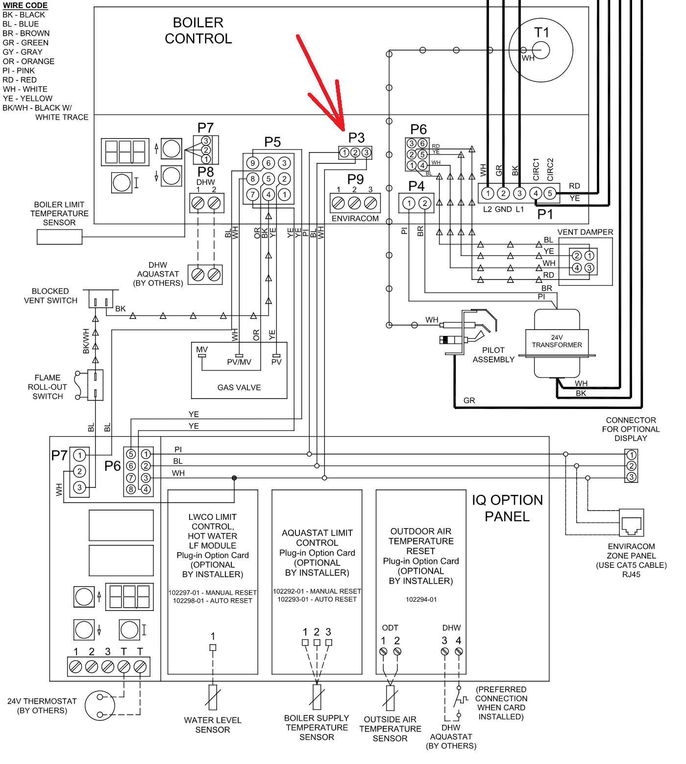
Since the error below (Err 89) does exist, I believe the Boiler Control board if the system had those optional cards present expects to see their presence once learned. Since your system has no optional daughter boards the question is, if there is an error with the IQ Option Board will the boiler still work or does it cause a Lockout. I can't find that info. in the manual.
I believe your assessment of the removal and replacement of the IQ Option Board is probably correct.
National - U.S. Gas Boiler 45+ Years Old
Steam 300 SQ. FT. - EDR 347
One Pipe System0 -
it appears it causes a lockout by opening blue-blue since both their tech and @EdTheHeaterMan bypassed its control of the boiler by shorting blue to blue.
i'm just not 100% sure i trust the conceptual dotted lines to be actual direct wired connections.
0 -
I suppose if you like to tempt fate to find out what happens you could disconnect P3 on the Boiler Control Board. I believe disconnecting P3 will power down the IQ Option Board and disconnect the EnviraCOM network from the Boiler Control Board. Leaving the T-T path intact.
I would shut the Boiler's power off before making any changes.
 National - U.S. Gas Boiler 45+ Years Old
Steam 300 SQ. FT. - EDR 347
One Pipe System0 -
I'm thinking @ftres was looking for a board (or an example of) that just jumpered the Blue to Blue wires and provided the T-T screw terminals. To simplify the boiler electrical. I do not believe that exists.
Since the Blue to Blue wires are now cut and connected towards the Boiler Control Board bypassing the IQ Option Board. The question now is will the boiler still work if the EnviraCOM network is disconnected between Boiler Control Board and the IQ Option Board and the IQ Option Board is powered down.
In other words does the Boiler Control Board need to see the IQ Option Board via the EnviraCOM network to prevent a Lockout due to a network fault.
National - U.S. Gas Boiler 45+ Years Old
Steam 300 SQ. FT. - EDR 347
One Pipe System0 -
To eliminate the entire system would require finding a location for the thermostat wires on the intelligent boiler control, because the boiler thermostat connection is located on the IQ panel. That is why it took me about 2 hours to remove the IQ panel. I needed to determine where all the unused wires needed to go, including the thermostat wires.
It is doable — I just cannot remember the exact details because it was so long ago. I believe the yellow wires connected to the 9-pin P5 connector, terminals 9 and 7, might have been the thermostat wires, but it has been long enough that I cannot be certain.
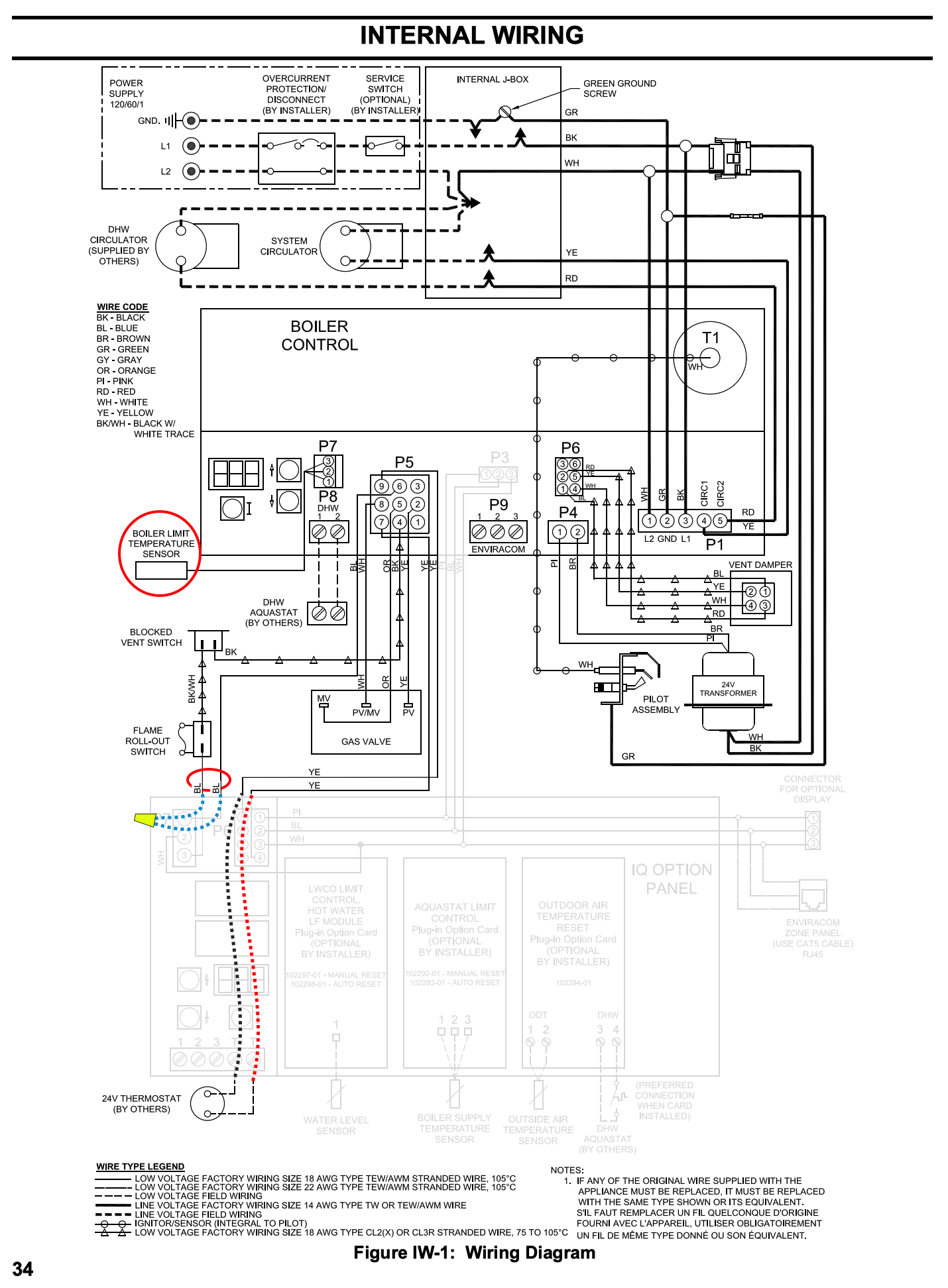
That will probably require some trial-and-error testing to determine whether the yellow wires are 24 VAC power from the transformer or the actual thermostat wires. A meter may help you determine that. Try connecting the yellow wires together with a fuse. If the fuse blows, then it is 24 VAC power for the IQ panel. If the system starts, then it is the thermostat circuit.
After that is determined, you can proceed with removing the IQ panel because all the remaining wires will be EnviraCOM system wiring that you are not using.
Edward Young Retired
After you make that expensive repair and you still have the same problem, What will you check next?
0 -
Thanks. What you're saying about the thermostat wires going to terminals 7 and 9 of the P5 connector lines up with my read of the diagram.
I'm not doing anything unless and until the boiler won't start again due to an IQ error. If it happens in the middle of the winter and I can't get someone quickly to take a look, I might try the suggestion of unplugging the P3 connector see if that powers down the IQ board and allows the boiler to start up. Seems pretty low risk assuming I power down the boiler first.
0 -
The more I think about it, the more I believe I used it on a Oil Fired boiler that used a L7248L oil burner aquastat that was compatible with the EnviroCOM communication bus. The Thermostat terminals were easy to locate on the L7248L, where the Gas Boiler Control illustrated below does not have those thermostat terminals clearly marked
Edward Young Retired
After you make that expensive repair and you still have the same problem, What will you check next?
 1
1 -
if you look at the oil version the control is slightly different and it is all broken out for the primary control
0


Categories
- All Categories
- 87.7K THE MAIN WALL
- 3.3K A-C, Heat Pumps & Refrigeration
- 59 Biomass
- 430 Carbon Monoxide Awareness
- 127 Chimneys & Flues
- 2.2K Domestic Hot Water
- 5.9K Gas Heating
- 121 Geothermal
- 170 Indoor-Air Quality
- 3.8K Oil Heating
- 79 Pipe Deterioration
- 1.1K Plumbing
- 6.6K Radiant Heating
- 396 Solar
- 16K Strictly Steam
- 3.5K Thermostats and Controls
- 56 Water Quality
- 51 Industry Classes
- 51 Job Opportunities
- 17 Recall Announcements