Radiant Pump Failed - Do I need to Bleed System?

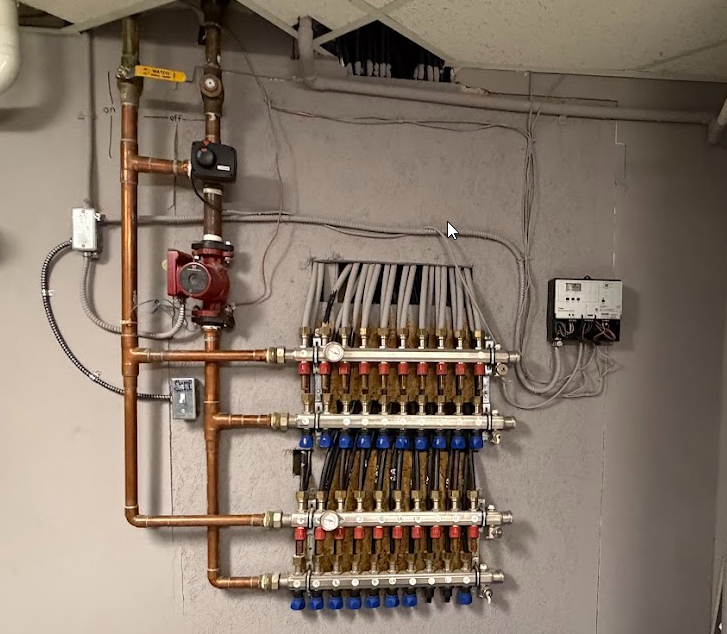
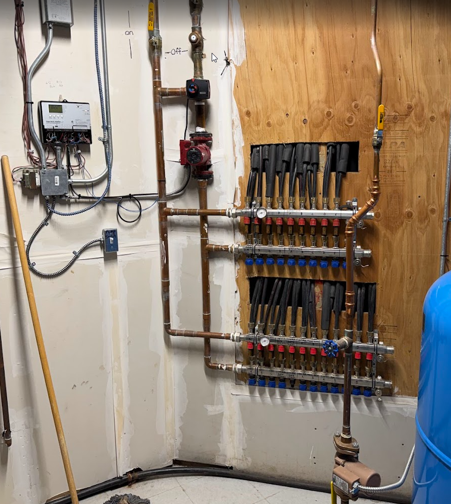
I have two radiant systems in my new house, this is the simpler of the two using a Viega Basic Heating Controller. I have diagnosed that the circulator pump is bad, the loop only works when the main circulation pump in the furnace room is running. This pump gets really warm when powered on and makes a ever so slight hum (and draws 120watts roughly) but it moves no water, you can hear nothing is moving.
I have found this pump on Amazon and am looking for guidance on replacing it. There are 2 valves on the supply and return so I can isolate this loop, but the radiant loops are all above it in elevation and i would imagine all the water is going to run out when I remove the pump. Unfortunately, I dont see any valves to shut off the manifold to prevent the water from leaking out.
Is there a way to prevent the water from leaking on these viega manifolds that I am missing? (the return side has the adjustment knobs but not on the supply manifold). Or do I just let it all drain and then let it refill? If so, I assume I need to bleed the air out of the system, can I do that myself without speciality equipment?
Thanks
Comments
-
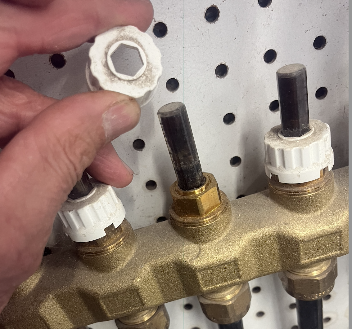
Just as you can turn the blue knobs on the manifold, you can also close the supply side by lifting the red rings and turning the flow setters clockwise.
By “lifting”, I mean moving them off of the flow setters. You may have to gently pry them away from the manifold with a screwdriver.
Bob Boan
You can choose to do what you want, but you cannot choose the consequences.0 -
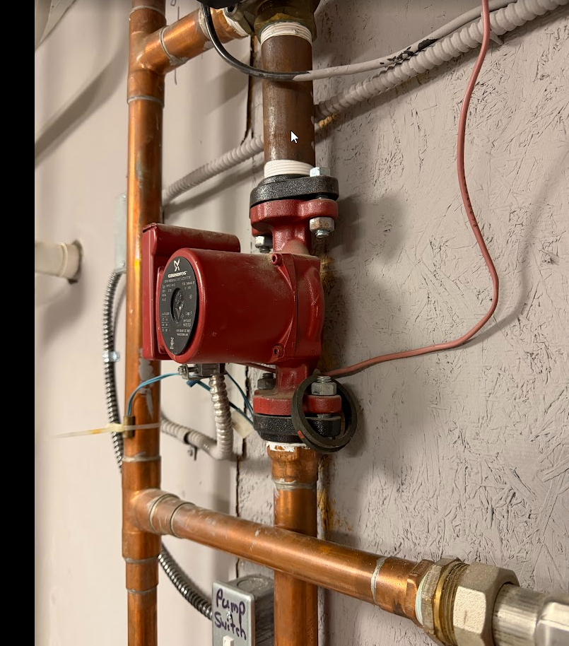
The pump appears to be in backwards (pumping downward?) so this might be a good opportunity to fix that as well. Lack of flow does not always mean a bad pump, it may simply be airlocked or that closed valve may be stopping flow as well. But to answer your question, yes a purge will likely be necessary after changing a circulator.
 2
2 -
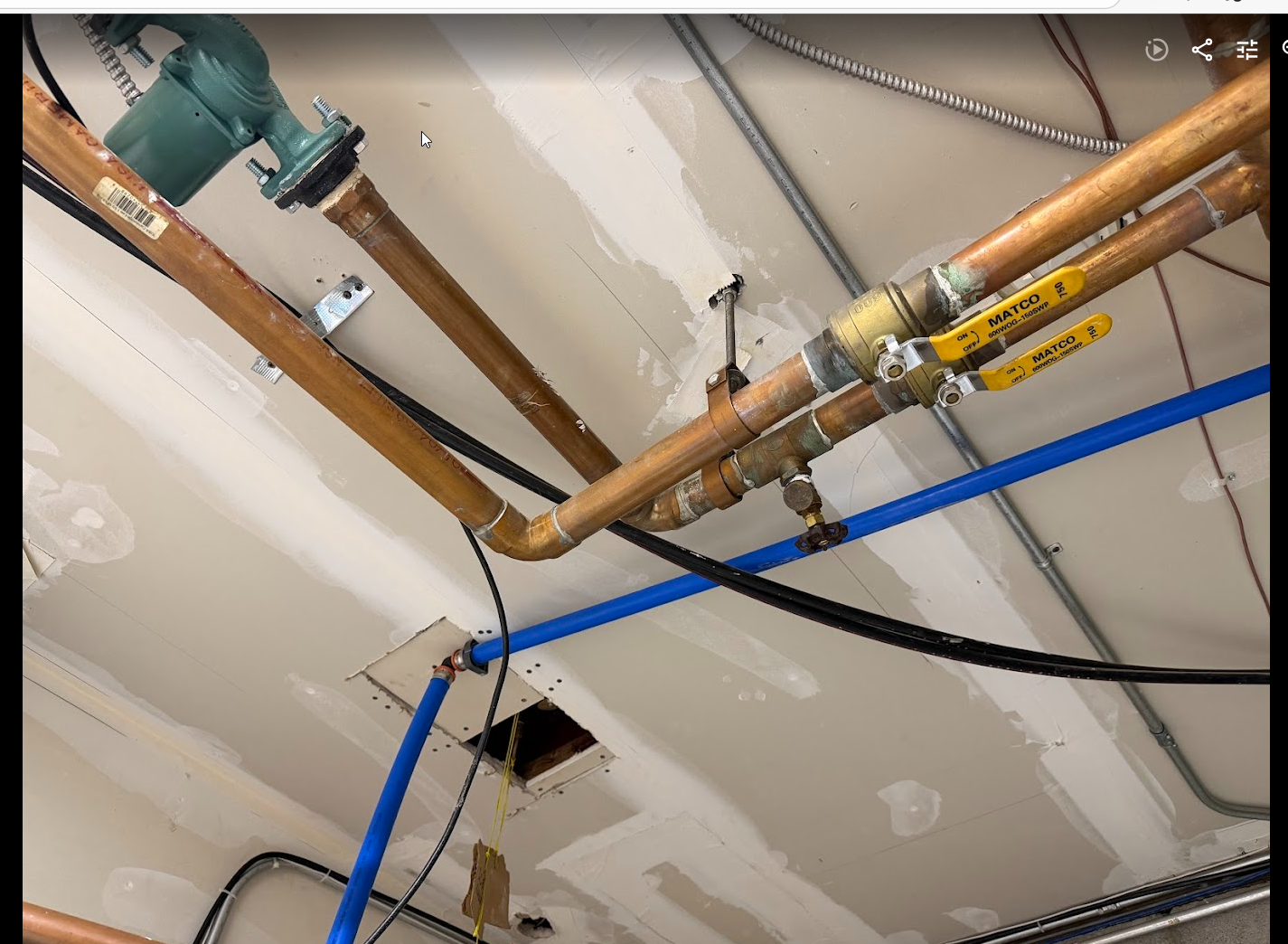
The valve to the right of the yellow handle ball valve, is that a check valve. It would have an arrow on it pointing up.
If so that valve and the yellow valve should prevent water from coming down from the boiler. Isolate all the loops as @ironman mentioned and you should be able to remove the pump.
Personally I would remove the 4 Allen bolts and remove the motor from the pump body. It could just have something stuck in the impeller. It may not need to be replaces, although I would have a new one on hand regardless.
A 4 mm or 5/32 T handle Allen wrench works best for removing those bolts.
If you buy the exact same circulator you can just swap the motors via those 4 bolts.

It's possible to do this without introducing much air. Install the new circ, leave the Allan bolts a bit loose. Then open the yellow valve slightly until water squirts from the pump. This may get any air out and the white air bleeders on the manifold may catch any remaining air.
Additionally the boiler should have an air purger?. Worth a try before doing a big purge and introducing fresh water and O2 into the system.
Bob "hot rod" Rohr
trainer for Caleffi NA
Living the hydronic dream 2
2 -
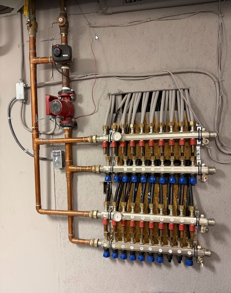
My concern was losing the original balance of the system. Is there a way to mark them so I can get them back to where they were? I spoke with Viega when requesting a manual and they told me the blue knobs should be wide open and never used to control flow, which is interesting because mine are all at different positions, so I think someone who didnt know what they were doing tried to balance each room this way.
I have been able to remove the red rings, but the flow setters are no longer movable by hand.
Maybe it makes sense to start over from some sane base line anyways and just close these all 100% to change the pump and then re-open them 100% and then balance one at a time using a laser IR temp meter on the floor……
0 -
The valve is closed for the picture but I make sure its open when testing.
With that pump on there is no noise. On my other manifold system in the other room, you can clearly hear when water is pumping through. This system makes noise when the main circulator is on (and water flows through it) so I dont think the pump impeller is siezed up, as you can hear it spinning when its being forced by the main circulator pump in the utility room.
I would be surprised if its backwards, the other system has the pump facing the same way and its working fine. But I wouldnt rule out anything since a lot of people who had no clue have messed with this before I bought the house. The pump should be pumping UP towards the mixing valve, pulling hot water into the red supply manifold and then out through the blue return manifold and then back to the furnace, correct?
EDIT: The arrow on the pump points UP
 0
0 -
Yes i believe its a check valve, but the good news is that right above it out of frame, is a another ball valve anyways, so I can isolate everything in the picture with those 2 ball valves.
Removing the pump from the body sounds like a good idea, as long as its not likely to introduce a leak in that seal. I dont think anything is likely in the impellar because I can hear it spin when the main circulation pump is running and forcing water through it. Oddly though, the pump is consuming current (About an amp or so) and putting out an electric field so it seems like its doing SOMETHING, just not moving water.
Regarding the air purger for the furnace, do you mean to ensure there is no air causing an issue? I dont think that would be the case because the other manifold/pump is working fine (which can be seen here:) The difference between the two, this one uses an advanced heating controller instead of the basic heating controller, no idea why they elected to go with this over the basic, maybe its what the installer had laying around, idk.
 0
0 -
Blue is the return manifold, so the pump is correct pumping up towards the mix device. If it has worked fine for years, it is ok.
The correct way to adjust flow is to first know what each loop was designed for, but...
Those plastic indicators also turn to make flow adjustments, that is usually where the adjustment is made, the blue valves should be wide open. So no problem turning the blue valves closed all the way.
On the red valves, pop the red ring off. Usually it is a hex shape, so it is the wrench to turn off or adjust flow. Slide it down on the clear plastic indicator and turn .
Count the turns it takes to close the valve and write it down for each loop, CW clockwise to close.
 Bob "hot rod" Rohr
trainer for Caleffi NA
Living the hydronic dream0 -
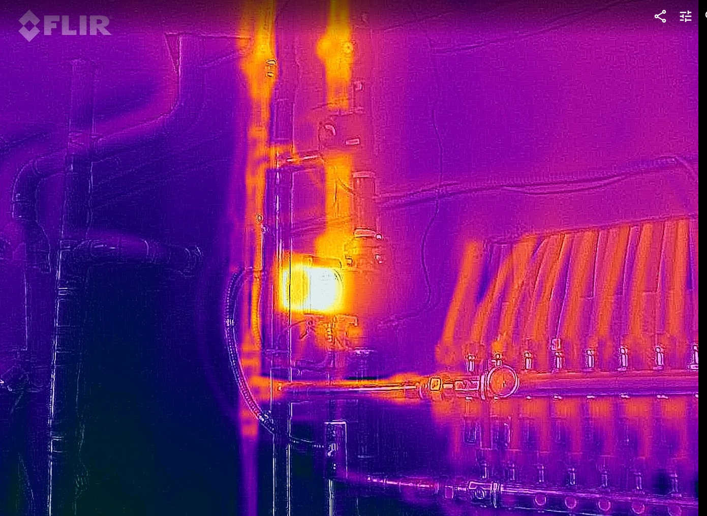
I was planning on opening one at a time when this is done and using my thermal camera to figure out exactly what each loop does. Then I will be able to adjust things down the road if needed.
Someone def thought they could balance the system using the blue knobs because they are all at various open positions…
My concern is I have never bled a system before and this one is pretty damn complicated. Even if I shut off the 2 ball valves and close each loop, and I let water flow out before tightening the allens, I am still going to introduce SOME air to the system, correct?
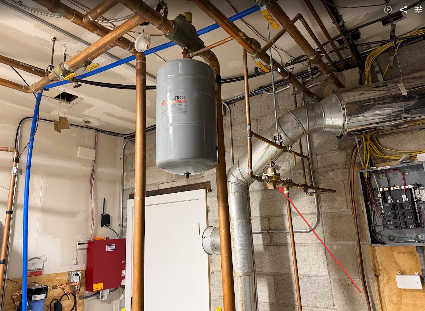
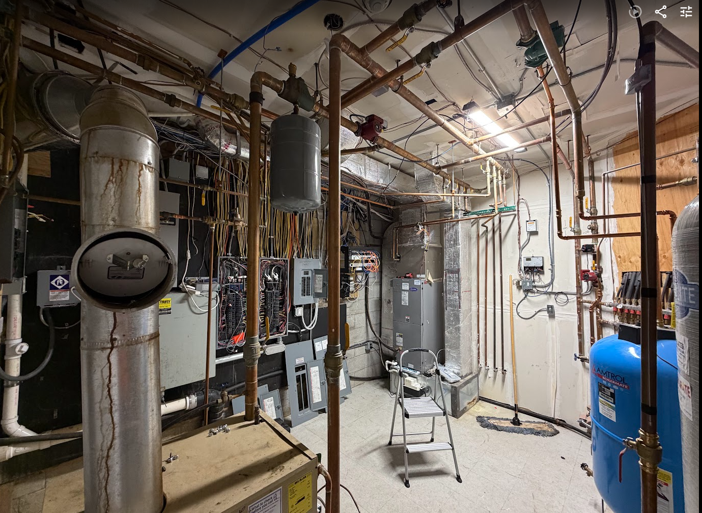
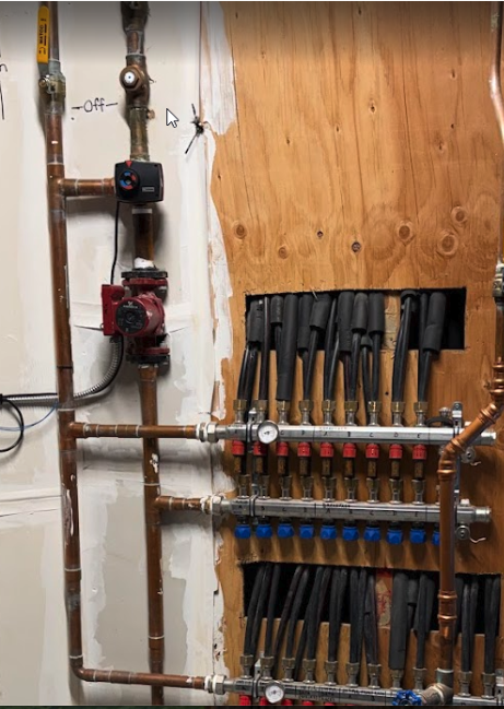
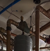
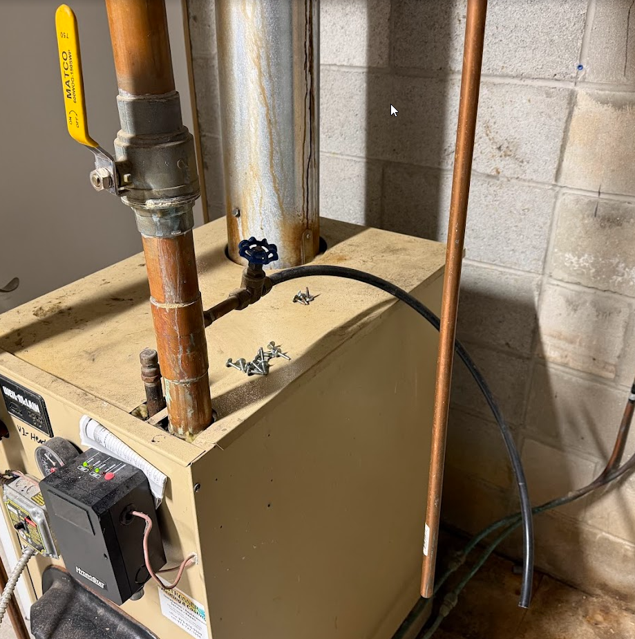
Red arrow points to bleeder for whole system, correct?
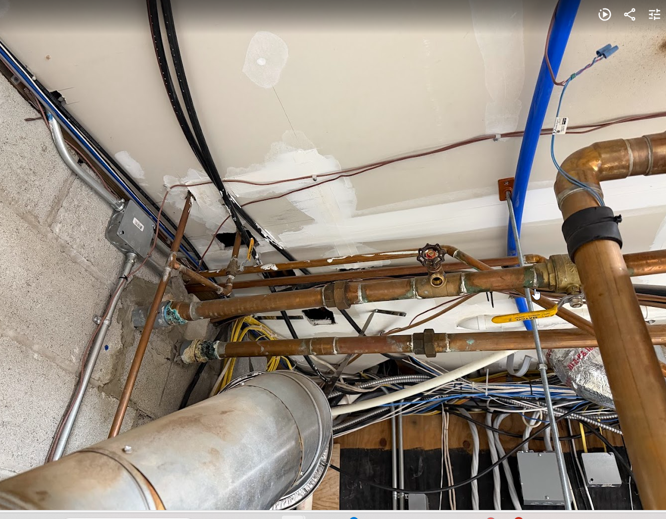
There is kind of a lot going on. Besides the indirect and the DWH recirc system, there heat feeds multiple heat exchange packs that sit on the forced air systems for each zone.
 0
0 -
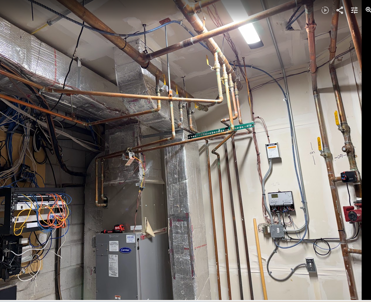
this shows all the circ pumps in the utility room
 0
0 -
I think that you’re more concerned with balancing than you need to be.
Once any air bleeding that’s required is done, just leave all the flow setters wide open and see how the system works for a few days. If all of the loops are close to the same length, you shouldn’t need any adjustments.
To bleed air:
- increase the system pressure at the fill valve to 25 psi
- Open the yellow supply valve above the pump
- Connect a drain hose to the drain connection at the end of the return manifold
- Turn off every flow setter and blue knob on the manifold
- Bleed air by opening only one flow setter and its return knob at a time. Do this with the drain open
- Close the loop and repeat the same on each loop, one at a time.
- Return the fill setting to 15 psi and let out pressure at the drain until it returns to 15 psi cold.
- Open all valves and flow setters.
Bob Boan
You can choose to do what you want, but you cannot choose the consequences.0 -
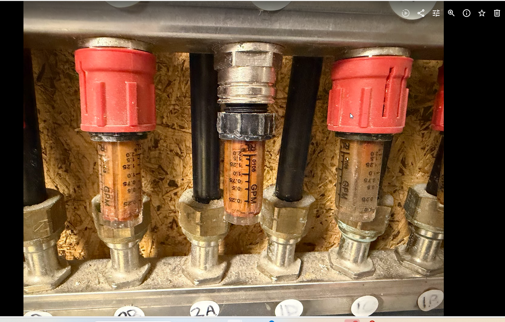
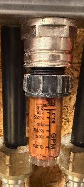
In reality there is not a lot of difference between the valve mechanism in the red or blue side. They both use flat EPDM washers. Flow could be regulated with the blue valve. Doing it on the flow indicators just simplifies the setting as you turn the knob. I suspect you indicators are fairly fogged and may not be easy to read anymore?
When the blue cap is removed and a thermal actuator is installed it basically acts as an on off valve that slowly, over 3 minutes or so opens, so it does operate at partial open conditions often.
No harm in trying to make the repair or sway and re-pressuring and see if it circulates. Small air will make it's way back to the purger above the boiler at some point.
Worse case you do a loop by loop purge.
I don't like seeing indications of that flue running in condensing mode, the water streaks on it. That could indicate long cold run cycles on the boiler.
A boiler like that connected to radiant really should have some return temperature protection. A look inside by the burners or a mirror in the flue damper would indicate it's health.
Might be a good idea to get the covers back on those breaker panels!
Bob "hot rod" Rohr
trainer for Caleffi NA
Living the hydronic dream1 -
Good catch, Bob. I didn’t see the water streaks until you mentioned it and I zoomed in. It also looks like it connects to a larger chimney which would add to the problem.
Bob Boan
You can choose to do what you want, but you cannot choose the consequences.0 -
@EBEBRATT-Ed always catches the electrical atrocities. Hopefully he is enjoying a day off :)
Bob "hot rod" Rohr
trainer for Caleffi NA
Living the hydronic dream0 -
Yeah they are pretty hard to view…. Under the blue knobs are just plastic valves, they are different than yours.
Regarding air making it back to the purger above the boiler, how will i know, or it purges automatically?
what kind of return protection should it have? One tech I had come out thought I should replace the mixing valves with buffer tanks, but his reasoning had nothing to do with cold boiler run protection.
I havent looked in the oil boiler myself, but I had a company service it when I moved in and they didnt comment on this or the health at all.
(yeah sorry about the panels, I am replacing a lot of switches with zwave switches and its much easier to use the circuit breaker finder probe tool with the covers off :)
0 -
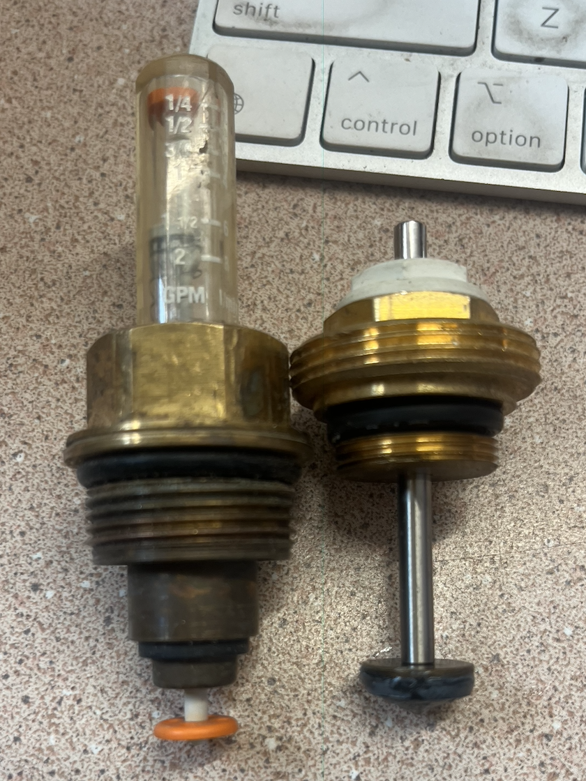
Usually you rotate those plastic indicators to adjust flow. However based on the age and knowing plastic gets brittle after time, you might not want to wrench on those plastic components.
It should look similar to this under the blue knob. As you turn the blue cap it pushes or releases this pin to move the valve mechanism.

Did Viega tell you how to make flow adjustments when you talked with them? Maybe send them a pic of the manifold to identify the vintage and parts available.

How much change or upgrade do you want to attempt? Perhaps Viega has rebuild parts for the manifold if you want to use and view those flow meters. Adding a boiler protection valve would take some work and drain down.
If you hear the pump spinning or vibrating, pulling current, not getting excessively hot, you could just have some air locked loops, or the mix valve jammed in a cold position?
Might be better to wait out the heating season to make major changes or upgrades.
I'd be saving for a mod con boiler upgrade based on the radiant system and a boiler that age and being potentially oversized?
Bob "hot rod" Rohr
trainer for Caleffi NA
Living the hydronic dream0 -
Viega said make flow adjustments by just turning them with pliar if needed. they said when they are new you can move them by hand but when older probably not. they also said dont bother messing with flow gauges, they said its not a good way to measure anything, they said much better to use an IR laser temp gun on the floors to adjust based on that and that it would jsut get dirty in a couple years again anyways…..
If i am not able to turn/close them, then i will need to drain all the loops to replace that motor unfortunately. Viega said they recommend you put valves in front of the manifolds but my installer didnt, they put them after the pump, which sucks for me.
As far as how much change, I want to get this thing fully restored and working properly. Funny, the techs that came out in the summer when I bought the house said to wait until winter to mess with it because it would be too hot to run it then.
I may not need to open the system to get it working better. It seems the main circulation pump that runs when the boiler runs is powerful enough to move the hot water through these loops without this pump doing anything. I have the valve open and am monitoring with FLIR and the loops are hot under the floor. The boiler runs a lot, and so it moves enough water. I dont know if that is bad for the main pump or what, but its working.
What I could do for now is try to get the controllers and mixing valves working properly again so I dont need to manually adjust the mixing valves to keep things working well. I ordered 2 replacement outdoor sensors and will install them when they arrive. With that, I should be able to get the controllers working properly.
As far as the boiler, not sure how to figure out if its over sized. I am not sure if its still condensing or if that was a one off event in the past because I havent see any water on the flue pipe since i bough the house.
0 -
@JoeDi Lucky for you that someone had the brains to install two ball valves.
I will give you my opinion for what its worth which may differ from others (what else is new).
If they system worked before change the pump and put it in the same direction. Don't touch the flow setters yet.
Put the pump in with the bolts a little loose and crack the valve on the left as @hot_rod said(don't get burnt). That will get most of the air out. Then tighten the pump open the valve and let her rip.
Get the system working before you mess with balancing. If you mess with too many things at once and it doesn't work its harder to troubleshoot.
Yes, @hot_rod I am eyeballing the electrical panels!!!
No days off for me.
0 -
Thank you, but if I dont touch the flow setters, then what keeps all the radiant loops connected to that manifold from draining out when I remove the pump? The ball valves will prevent me from losing water from the rest of the system, but this room is below the loops in elevation, so i would expect the loops to drain out or am I missing something?
Thanks
0 -
Yes water will drain back from all the loops if you cannot turn them off. But I would not wrench on those old plastic flow setters! Unless you have a plan B? If you break one you will need to isolate that loop completely to get you system running.
I would probably bite the bullet and drain down instead of cranking either the blue knobs or flowsetters.
In a perfect world the original load and design sheet tells you where to set all those flowsetters, as the loop lengths and room loads vary. So they do serve an important function to balance the system. If only used for commissioning the first time.
Balancing devices like that are to "fine tune" a system. They are also helpful to troubleshoot.
But unless you are very diligent with water quality and conditioners, they get clouded up within weeks of installation and are not much use.
It looks like those could be removed in the summer, with the black nut, soaked in CLR and cleaned up. Or replaced.
Based on that rust water, the mix valve could be scaled also. You should be able to remove the black motor and turn the valve manually.

There should be a test button on the control. press that and the valve should rotate through an open-close, then back to the desired position. Observe the blue/ red knob, it may take a few minutes.
 Bob "hot rod" Rohr
trainer for Caleffi NA
Living the hydronic dream0 -
Thank you, you read my mind on my next question!
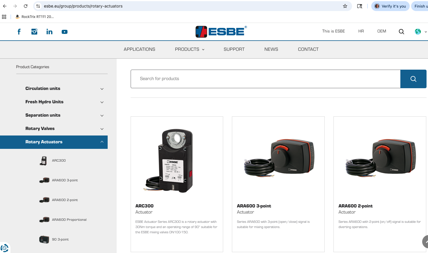
I am able to manually actuate the mixing valve by pushing in the knob and turning. I can see the plastic arrow behind the actuator point from 0 to 9 when I adjust it, and the system changes based on that.
However, this plastic arrow behind the actuator does NOT move when the mixing valve is commanded to open and close, which I assume it should?
Part of the problem could be its set to station and not bloc. Viega says that ESBE actuator should be set to Bloc on the dip switch.
I am going to run the test as you recommended and see.
Regarding the drain down. I guess it depends if there is any issue with just letting the main ciculation pump do the duty when the furnace runs for now? If there is no issue with that, and leaving my mixing pump dead, then i could just wait to mess with the pump after heating season.
However, worse case scenario, I can just go back to having those ball valves closed and disable the whole loop. It wasnt running until now anyways, we have sufficient heat from the forced air systems with the hot water heat exhangers that sit on them. that functions enough without the radiant running at all. so if i wrench on the manifold and it causes a leak, i can just disable the whole radiant loop.
So its a matter of weighing that vs just letting the main circ pump do the job for now vs draining down the loops. My only concern with draining down the loops is I have no experience air bleeding a heatign system, so i would need some hand holding to do it, but i am sure i can with some guidance.
0 -
A system with that many loops is probably not for the novice to purge, no offense.
At your fill valve you have a bypass valve that allows your home water pressure into the boiler. But you need to monitor boiler pressure when you use the bypass or you could trip the relief valve and make a mess.
It works best with two people, one monitoring and regulating that fill, the other concentrating on purging the loops. Probably 1 maybe 2 loops at once can be purged, so you have some work to do.
It's been a while since I played with an Esbe mixer. I think you should see some visual when the motor is actuating? As you do with the manual operation. It could have a bad motor or broken coupler? Does the motor buzz or hum? Is so, remove and check the coupler.
ESBE is still around, maybe part of Danfoss now, if you need parts
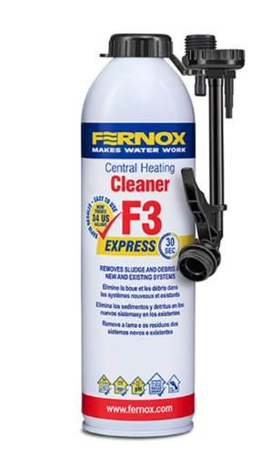
My suggestion if you are doing a drain down is to first squirt a can or two of cleaner into the system and run a few days. I'll bet you could clean up all the piping and components nicely. Rotary valves prefer clean water :)
Maybe even clean the flowsetter windows. These cans screw right onto a hose valve, like the boiler drain or the valves at you manifolds. Tighten and pull the trigger.
Various brands out there Fernox, Axiom, Rhomar for example
 Bob "hot rod" Rohr
trainer for Caleffi NA
Living the hydronic dream1 -
So I've done a lot more research and studying of this system. I have determined the following:
- The mixing valves/actuators now work properly after I fixed some settings on the controllers. They fully actuate for test mode. They also now work as expected based on target temp. I believe once I get the outdoor sensors fixed, they will start functioning normally now!
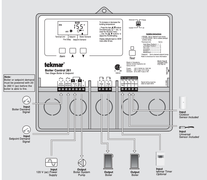
- I have cool water return protection or at least should via the Advanced Heating Controller. This explains why they installed the advanced controller instead of 2 basic controllers. its supposed to reduce the output using the mixing valve when the water is too cold. Still trying to study if its actually performing it.
- The advanced controller is supposed to control both the boiler and radiant floor loops. I am still studying how the boiler control works.
- I was able to turn the blue knobs by hand and the black plastic suppy valves on the manifolds with slight wrench pressure. I think I can safely shut them all off to change the pump. I think I am going to try it using the methods you guys gave me, replace just the motor and leave the allens loose and then let water come out. I figure I might as well try to close them because i need to do it to purge them anyways…
- I confirmed i have an air seperator/remover at the boiler. Do I need to do anything to activate the white ones on the manifolds? (the viega tech said they suck though)
You guys are an immense resource and I thank you.
0 -
Is this noise just a leaky valve (either the check valve or the mixing valve) or does it mean I have air in the system? Both loops make this noise in the same area, cant tell which its coming from. It only makes the noise when the mixing valve is at certain positions so I assume its the mixing valve making the noise:
0 -
After managing to get all the loops closed up, I removed the pump with the 4 allens. Oddly, only about 1/2 a cup of water fell from above, i expected to lose a lot more, I guess due to no air it can't fall out more?
Should I still crack the fill ball valve and let hot water come through before i close it up?
Does the return ball valve need to be open when I do that?
I assume the mixing valve needs to be wide open or middle position so that the water can get to the pump….
EDIT: I left the pump very loose, i can shake it in the housing. I crack the supply valve and it makes no rushing noise or anything, water doesnt move at all. I have tried the mixing valve fully open, fully closed and in the middle. I assume the check valve on the outlet of the pump is the reason why i cant do the trick to let the water flow out. At the same time, that means i added very little air. Can I just button this up and keep the loops closed for now and send this air back towards the boiler and hope the boiler air remover will handle it? Im not sure if this is enough air to be a major issue or not.
0 -
Ok after doing more research on this, I am fairly sure I wont be able to do the water out the pump trick because of the check valve. So I either need to let the small amount of air into the main system and hope all the air eliminators will remove it OR keep the air captured in this radiant section and purge from here.
Not sure what to do…. Not sure if this is enough air to matter. My concern is if the air gets into the main system and its not removed automatically its going to be much harder to remove it since I have 5 zones + 2 radiant systems. Where right now its isolated in this radiant system at least…..
0 -
Hard to know without trying something. Even with the check on one side, if you crack open the yellow ball valve flow comes down, goes around the loop and pushes any small air out around the loose pump motor.
It doesn't matter which direction the flow comes from.
If you drain down the entire system to make the pump change you will have a bigger purge project that trying to isolate as much as possible and purge out the pump bolts.
A freeze cuff below the pump is an option, but you are still depending on the check above the mixing valve to hold. Though even if it is not a bubble tight check, it would probably hold enough to do a quick 30 second pump motor change.
Even if you hire a pro to do this, they have the same decisions to make. The pump switch will be simple, the purging of that system could take hours to get right.
Unfortunately you do not have a great air purger above the boiler and it should have had 18- 24" of straight piping upstream to work best. So a good power purge is pretty important.
\
If you do a complete drain down I would consider adding ball valves at each manifolds, you have plenty of room to press in a couple valves. You or someone will need to isolate again some day. Ball valves are cheap, compared to a pros labor rate :)
Bob "hot rod" Rohr
trainer for Caleffi NA
Living the hydronic dream0 -
Sorry @hot_rod i posted so much that you probably missed that I already replaced the pump without a drain down. I was able to shut off all the manifold valves on both and only lost 1/2 cup of water when i replaced the pump. So very little air was introduced.
Right now the loop is entirely closed at every port, so that is why no water is coming through the motor bolts. I thought it might come from the mixing valve direction until I realized a check valve in the motor would prevent that. I can open 1 loop to let water pass and then water will come into the motor and I can try the bolt method.
I will try that.
0 -
I see that you mentioed losing only about a cup of water from the pump sway, so if you open any loop and let some flow down it should be good to go.
Early vintage Grundof pumps had a screw slot bolt that could be loosened to vent the motor.
Then a label was added covering that bolt. It could still have a bolt under the label if you pop it off/ Or maybe the stopped using that design.
It was helpful for bleeding and confirming the motor was spinning
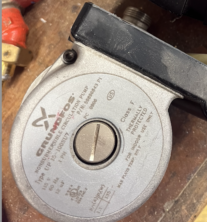
.
The PC number is the date code by the way, year and week of manufacture
Bob "hot rod" Rohr
trainer for Caleffi NA
Living the hydronic dream0 -
Small air bubbles tend to trap at the highest point in the system, driven up by buoyancy when the pump is off.
Also in the longest loops where flow velocity is the slowest. So probably the circ will start moving flow and push any small bubbles around or larger flow stopping bubble in the loops.
But you have good purge ports at the manifolds to get rid of loop air.
Bob "hot rod" Rohr
trainer for Caleffi NA
Living the hydronic dream0 -
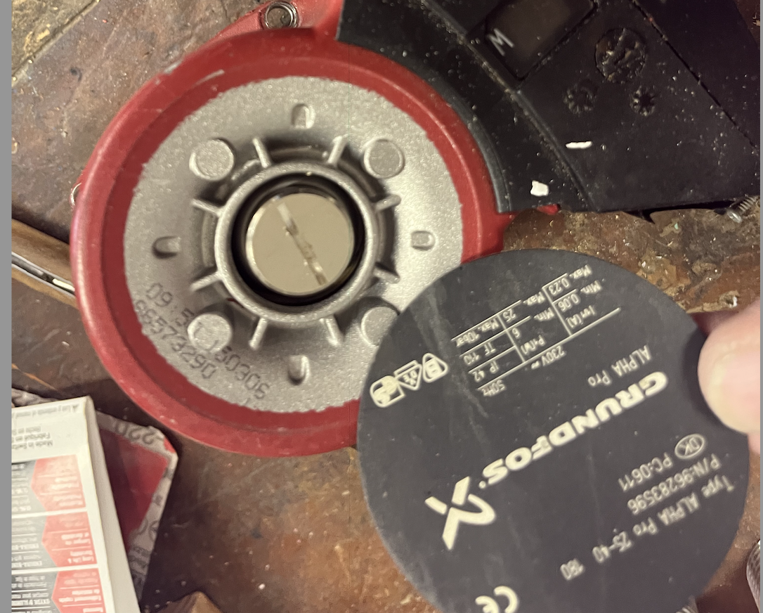
Ok i managed to burp out the air from the motor as you instructed. I hear air gasp out when i opened the allen bolts and then when I cracked the supply valve, i waited until i had water flowing out from 360 of the motor and then closed up the allen bolts. So far no issues from what I can tell, I dont hear any air in the system beyond what was already there and everything seems working ok.
However, I am going to wait until tomorrow to power up the new motor, when I did the water push out, i guess water got in the electrical housing as i had small amounts of it coming out of the ground terminal for a bit. I figured why risk shorting a brand new pump and instead will wait until tomorrow to fire it up.
When I fire up the pump, i will open the loops one a time and inspect with my FLIR camera to be able to write down what each loop does.
Fingers crossed I wont need to do any major purging.
0 -
Sorry, I am trying to learn as much about this as possible. When you say purge ports, you mean the actual drains on the returns that i can crack open and pump water out of, correct? Or do you mean the white air purgers that sit above the drain port? I am not really sure how they work, Ive not yet found a good manual for my manifold but the Veiga guy said they werent great, so I assume that means they arent very effective normally at removing air automatically?
If i did get air, is it likely to go to the highest point int the entire system or the highest point in the radiant loops? I checked my highest coil packs whih are the highest zones in the house and they are still just as hot as before. TBD if the loops operate as expected, find that out tomorrow.
0 -
At the end if the manifolds are purge ports that a hose can connect to. This is how you can purge loops right at the manifold without flowing though the entire system
Im with you, give it a try as you have now.
Bob "hot rod" Rohr
trainer for Caleffi NA
Living the hydronic dream0 -
I've got the new pump running and 2 loops on 1 manifold open. There is def a little air, I can hear some small bubbles at the pump but it did get quieter after a while.
There is def some air in the main trunk in the utility room but it was there before as well, maybe it got a little louder.
My plan was to wait to see if the air gets eliminated before I open the rest of the loops and let air into them as well. However, I believe most of the air is in the main trunk loop. Not sure where the purge station would be for that main loop. I also dont see any way to purge the loops going to my hydro coil heat exchangers.
0 -
Yep, let it run, for a few days.
A few other things that help air removal. Increasing the boiler temperature drives air out, and raising the fill pressure for a period of time.
The small pressure increase can squeeze rouge air bubbles so the flow back to the centeral air purger better.
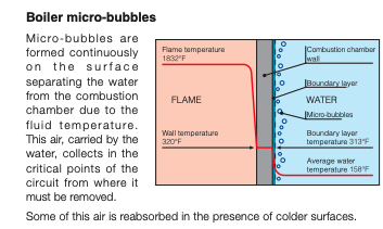
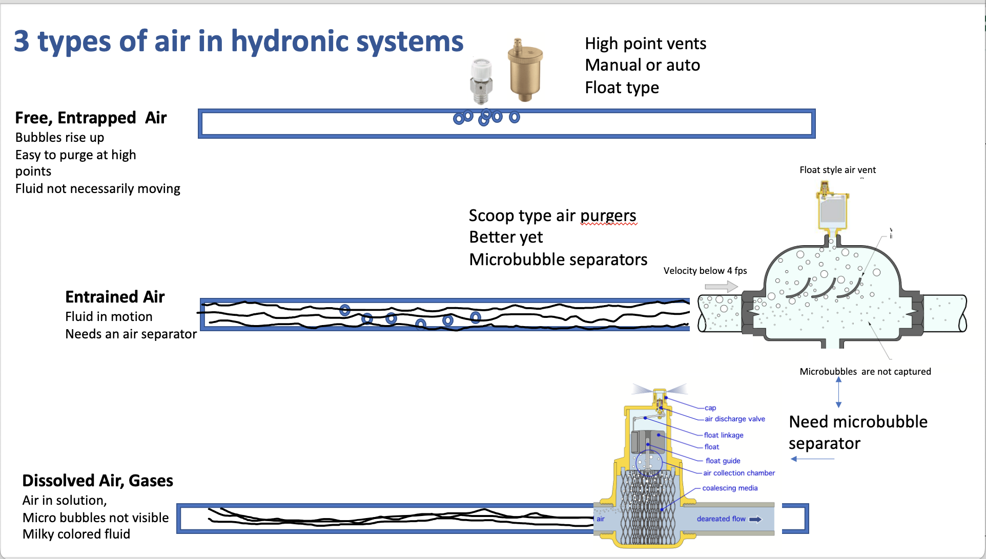
This pic shows how air is driven out of solution at the hot boiler surfaces. If the air is not eliminated it goes back into solution when the boiler cools, and you start over.
Over a period of time it should get to a 100% air free, quiet operation.
It is not uncommon to not see an air removal device in that indirect piping, that air with a good flow rate should push back to the purger. Some tanks have a small float type auto vent on top.
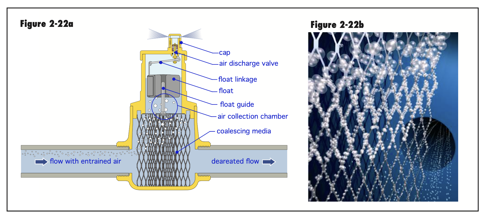
The type of purger you have are a bit of older technology. Newer microbubble type use a media inside to help grab tiny bubbles that can just flow across the purgers like you have.
\With some luck and some time the scoop type air purger yo have will get most of the air eliminated :)
Another upgrade option, a microbubble separator, . should you choose to improve air removal time and efficiency. Microbubbles entrained in the water are often smaller tha the eye can detect.

 Bob "hot rod" Rohr
trainer for Caleffi NA
Living the hydronic dream0 -
I think the boiler is already running pretty hot because I notice the Hydrostat on the oil furnace has a high temp light that turns orange often. (I've never seen it turn red and shut down the system though)
I am open to installing a better air seperator like one the modern micro bubble units but I assume I would need to drain down a large amount of the system. Besides the 4 purge stations on the 4 radiant return manifolds, I have only found the following other purge stations:
Not sure if this one is specifically only for servicing the boiler itself:
This one is on the return for the long run to the other room where the other 2 radiant manifolds are:
This is the return from the DHW Indirect:
There are none for the individual hydro coil heat exchanger pack runs, and some of them are pretty long distance runs:
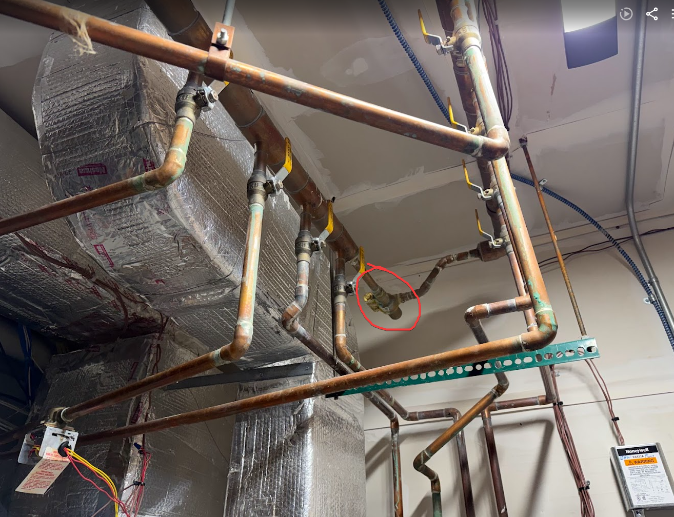
There is also this device that connects the supply trunk to the return trunk that was leaking. I believe its a pressure differential bypass valve but I had 2 companies say they werent sure. I ave been googling around and cant find one that looks the same with the extra cylinder on the side….. Anyone for sure know what this is? I guess the corrosion sealed the leak but I dont know if its working as it should. I bring it up partly because its up on the supply manifold is, so maybe it makes sense when this is replaced to also install a micro bubble air scrubber at the same time….
However, what happens if one of these hydro coil lines is ever air locked with no way to bleed them? You ca see in this picture how the one for the basement is plumbed since its in the same room.
There are valves on all the points that the main trunk is tapped, so at least it could be isolated if i opened it up to install the air seperator.
Thanks again for all the help!
0 -
well there are a number of places for some upgrade work
You might run with it for this heating season and make a list of future projects
That looks like a Honeywell PAB, the side window allowed you to confirm settings and operations
If it was set correctly as zones close off that crossover pipe should get warm
With all zones open it should close off, no flow going across
With todays variable speed circulators PAB are not so common
Whoever designed and installed this did a fairly good job, it is typical of that time period.
it’s obvious where a few more valves could have made it more user friendly
 Bob "hot rod" Rohr
trainer for Caleffi NA
Living the hydronic dream0


Categories
- All Categories
- 87.6K THE MAIN WALL
- 3.3K A-C, Heat Pumps & Refrigeration
- 59 Biomass
- 429 Carbon Monoxide Awareness
- 124 Chimneys & Flues
- 2.2K Domestic Hot Water
- 5.9K Gas Heating
- 119 Geothermal
- 168 Indoor-Air Quality
- 3.8K Oil Heating
- 78 Pipe Deterioration
- 1K Plumbing
- 6.6K Radiant Heating
- 394 Solar
- 16K Strictly Steam
- 3.5K Thermostats and Controls
- 56 Water Quality
- 51 Industry Classes
- 50 Job Opportunities
- 18 Recall Announcements