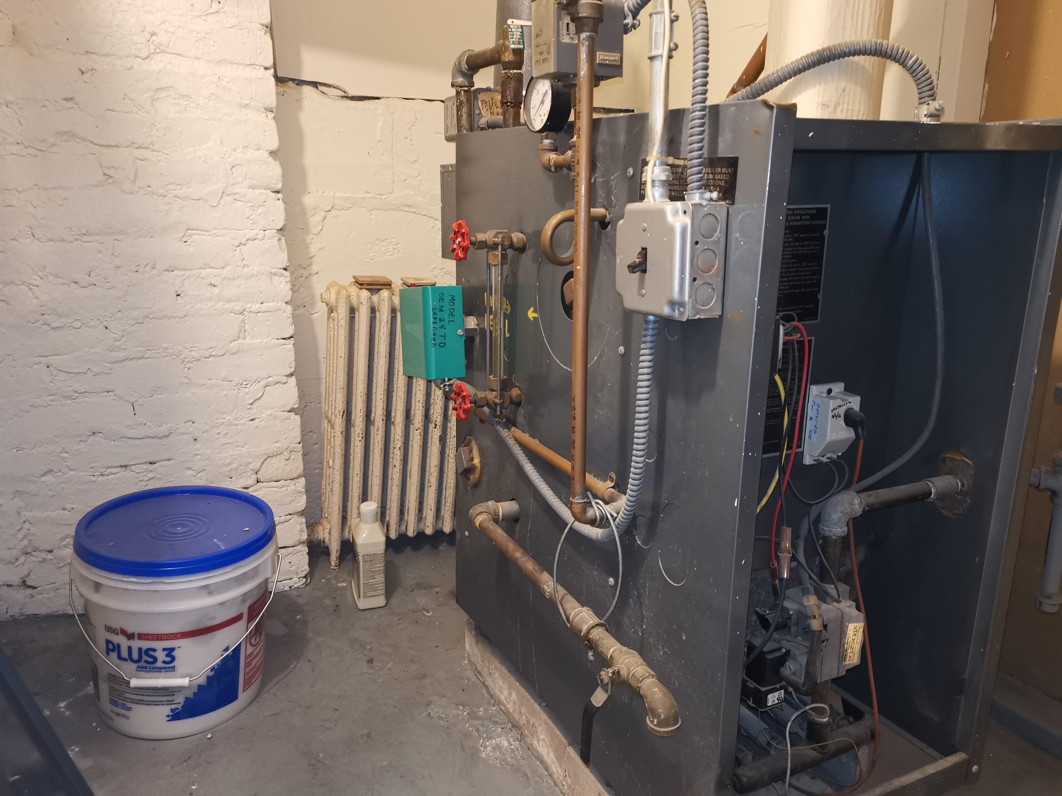
Old Weil-Mclain Boiler No response.

Weil-McLain eg-35-pi, probably over 20 years old.
I have a wood stove so the boiler didn't fire up much this winter. Last time it worked was probably 10 days ago for about 30 minutes. It's in the basement with ambient temperature about 50-60 F. Water level was not low, about 1" lower than the middle of the side view glass, and I added about 1 gallon water to make it sit at middle now.
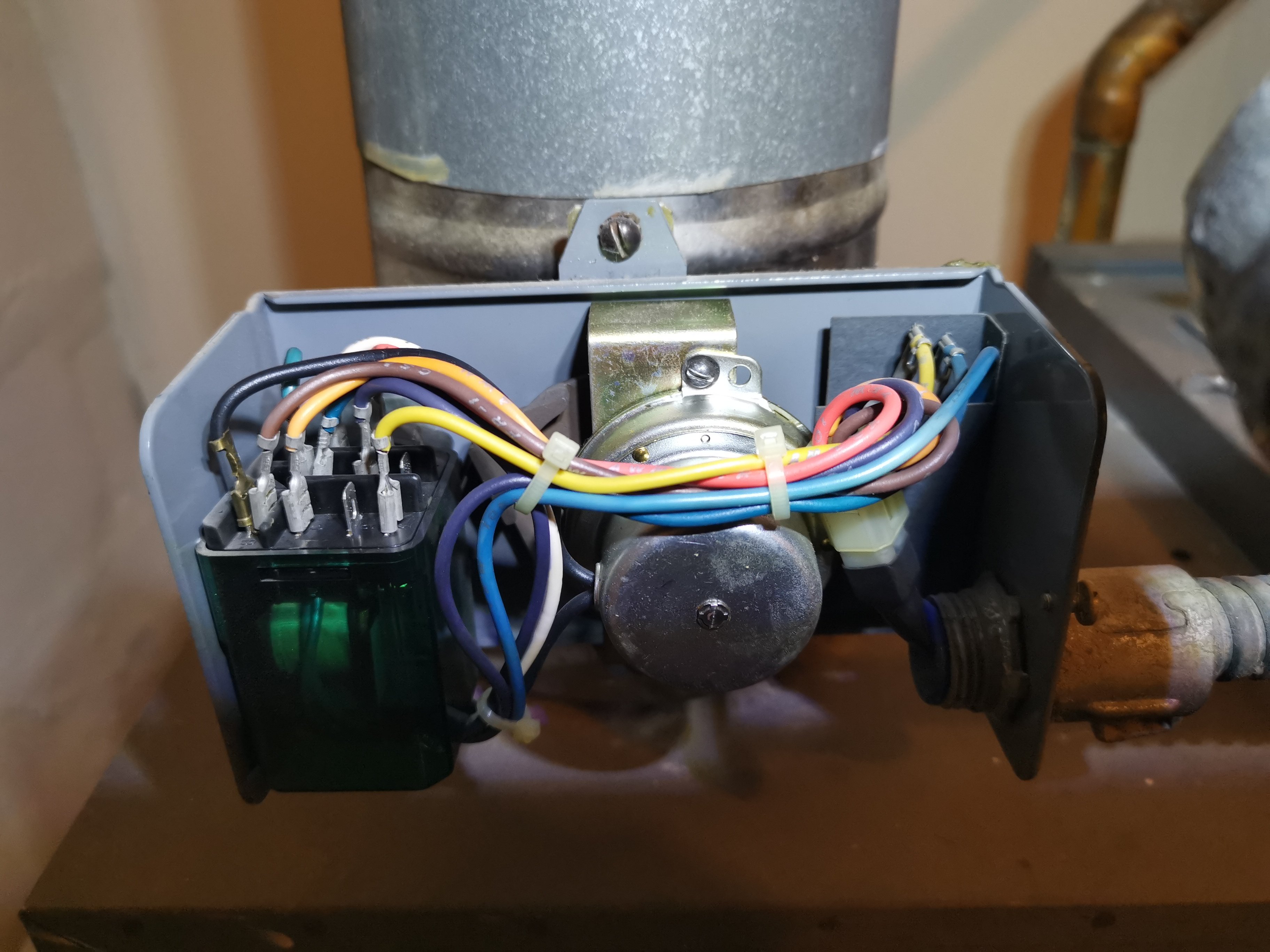
When the thermostat call for heat, there is no response at all. There is a faint buzzing/humming electricity sound when the power switch is on, and the sound seems to be coming from the transformer.
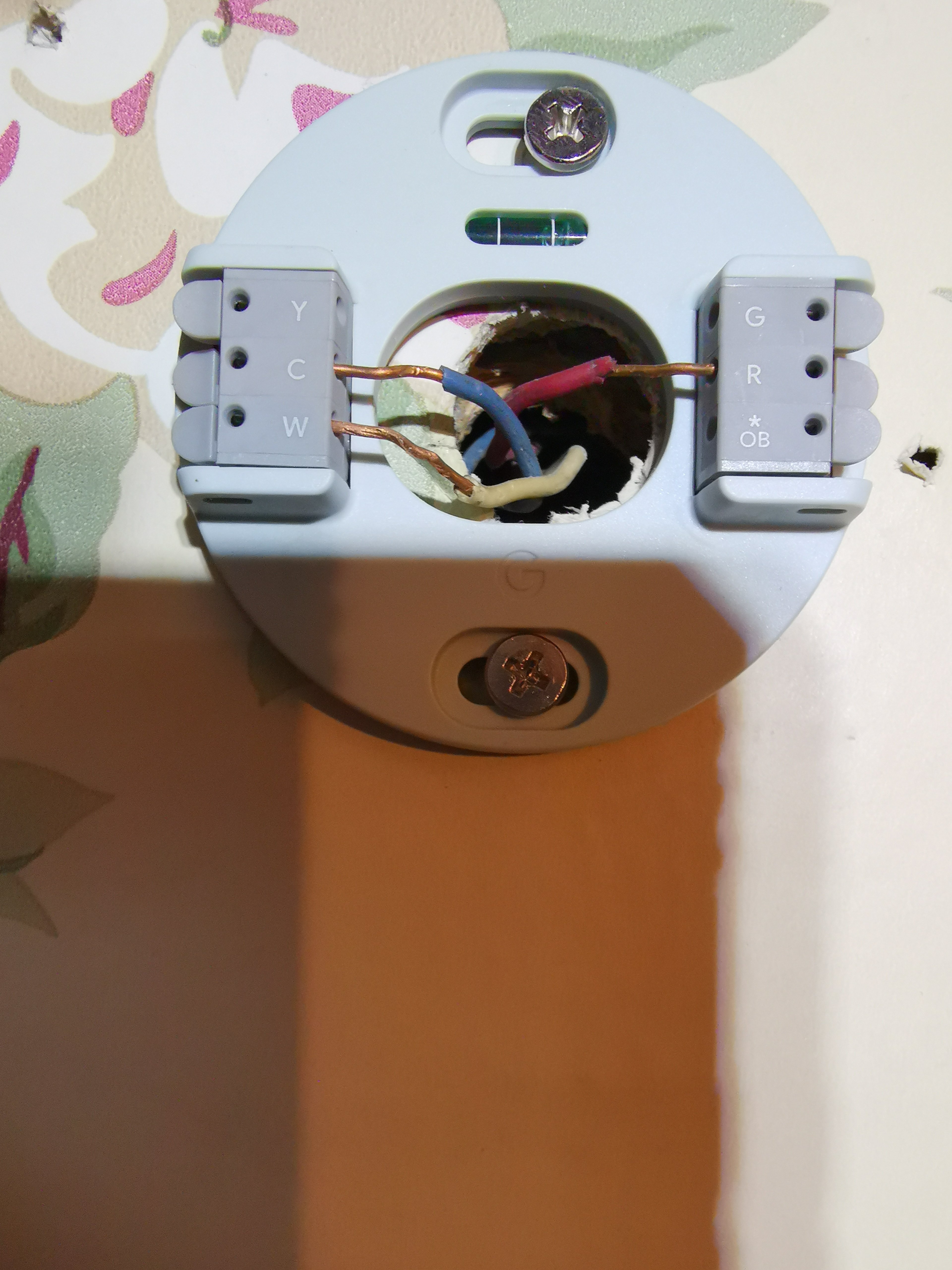
I swapped the thermostat (google nest) with one I know working. Same thing no response.
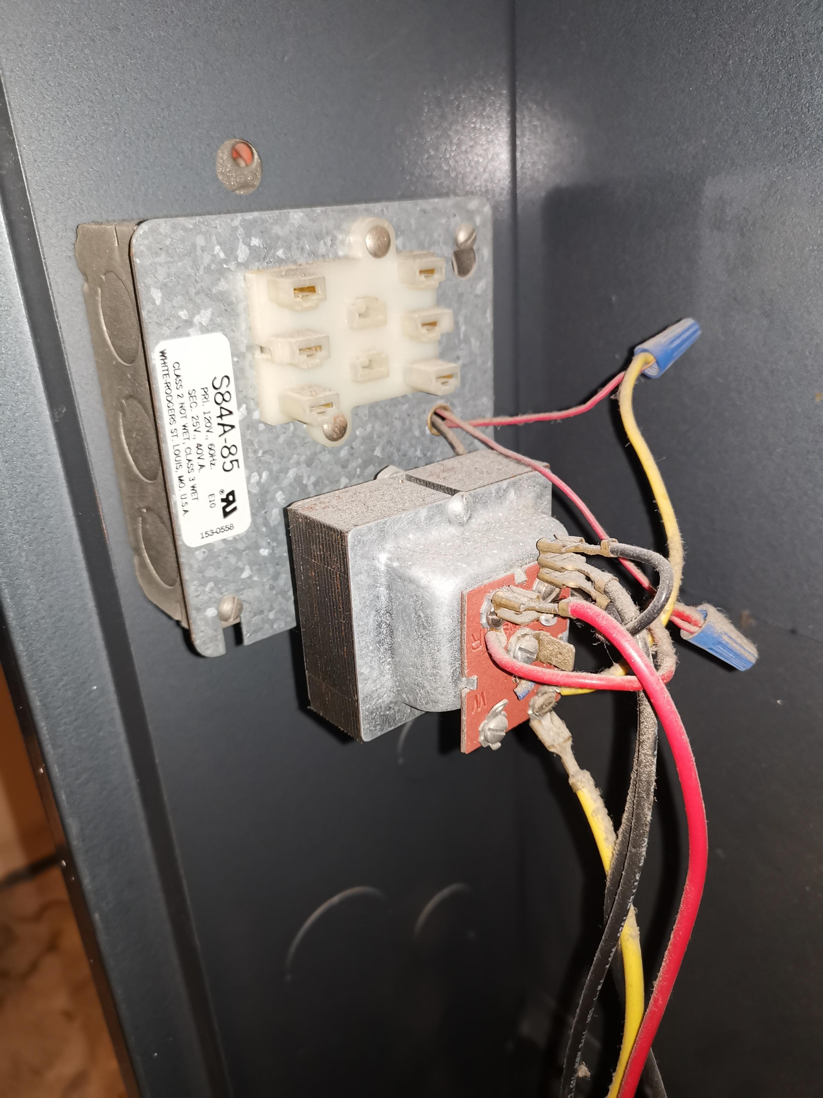
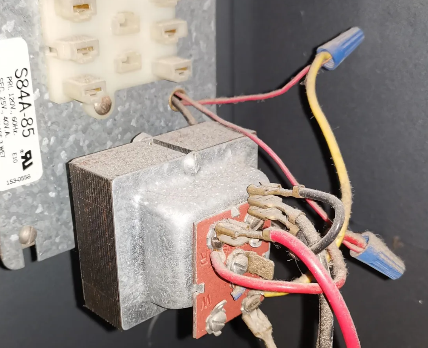
I used a multi-meter to test the transformer and it's 26 V between terminal R and C. Didn't test other combo because I'm not sure how it's wired and it seems a bit different from some search results here.
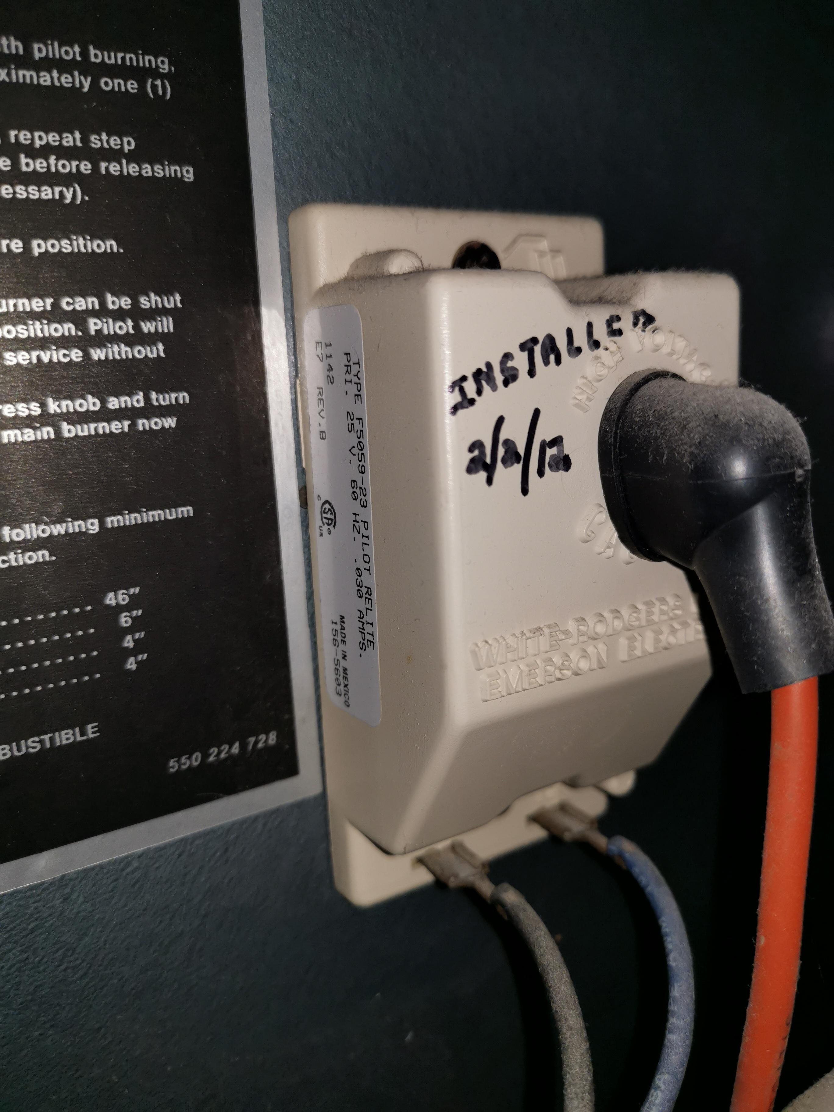
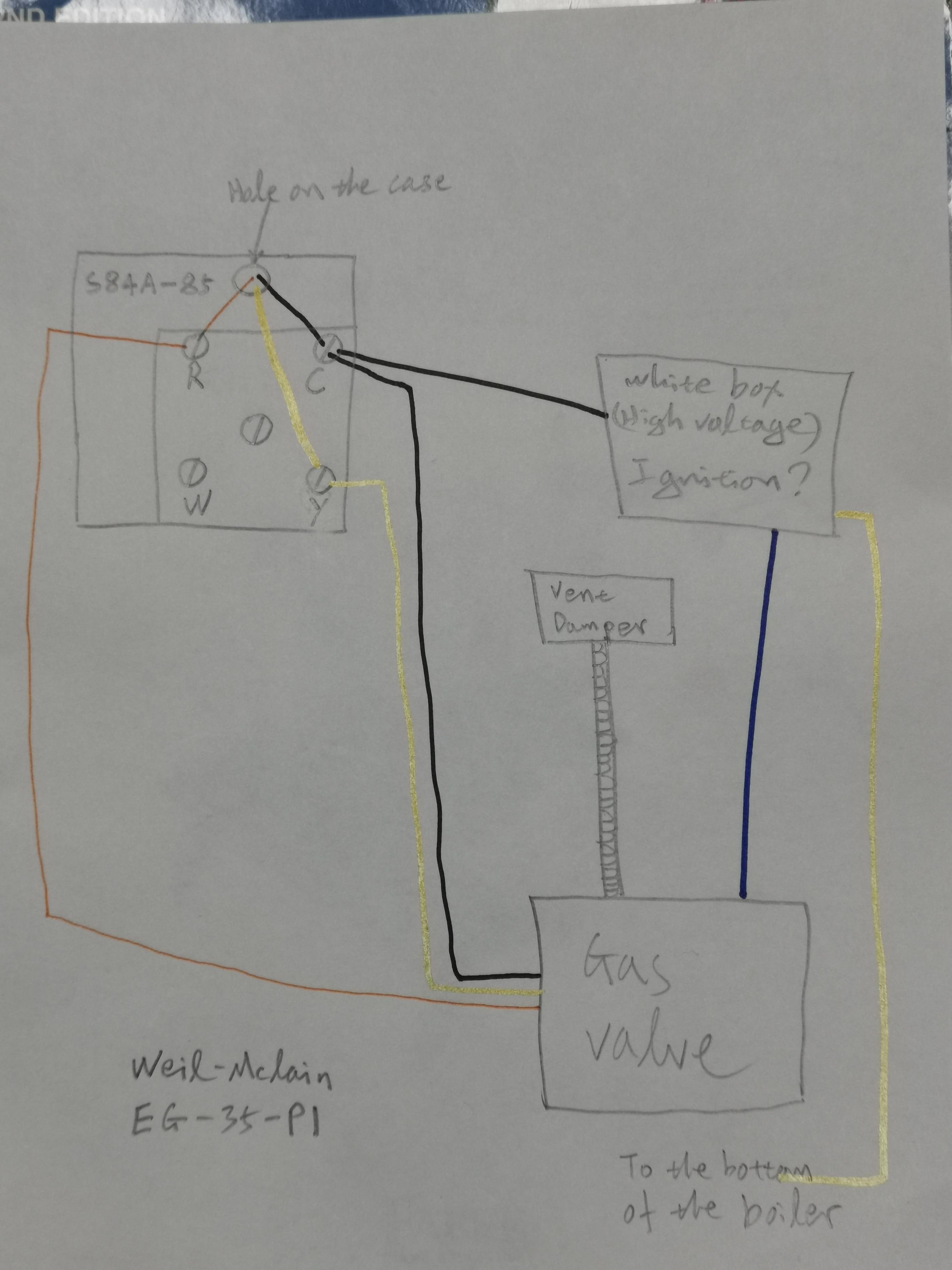
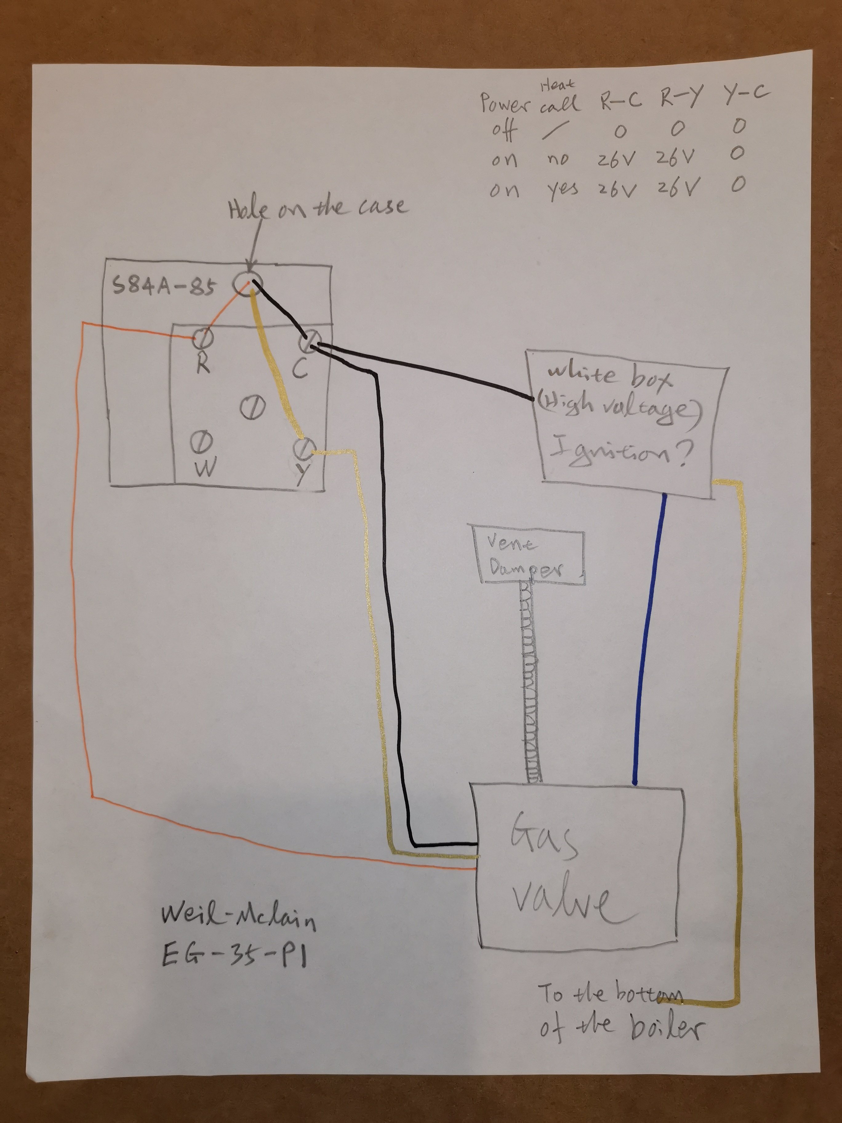
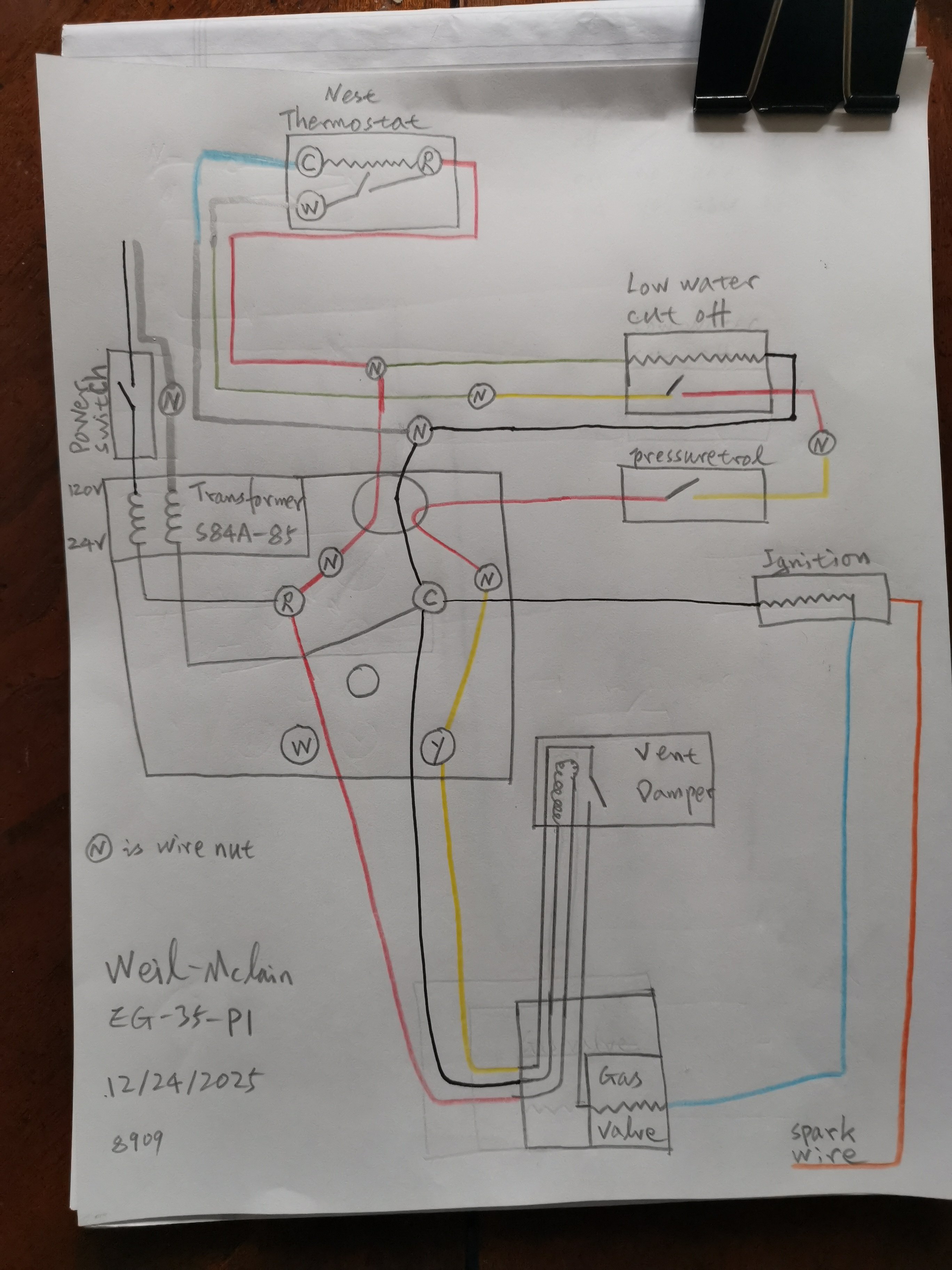
It doesn't have a wiring diagram so I drew one. I think the white box is for ignition?
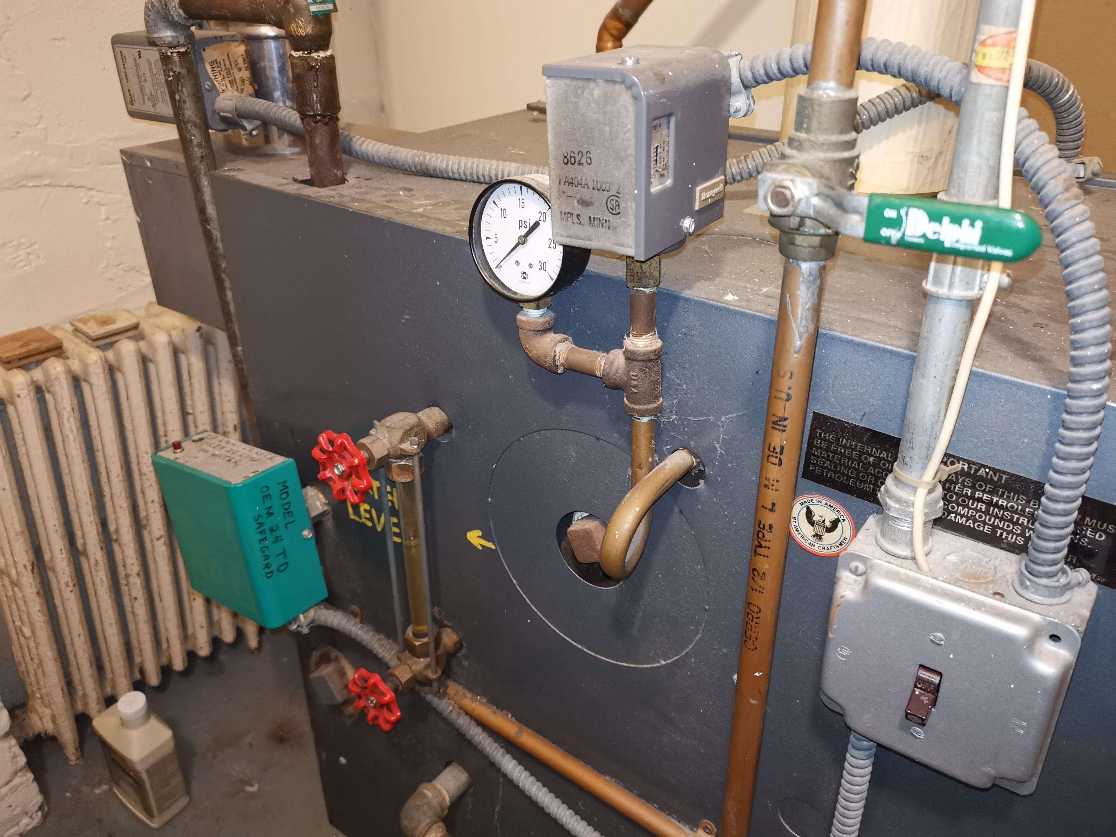
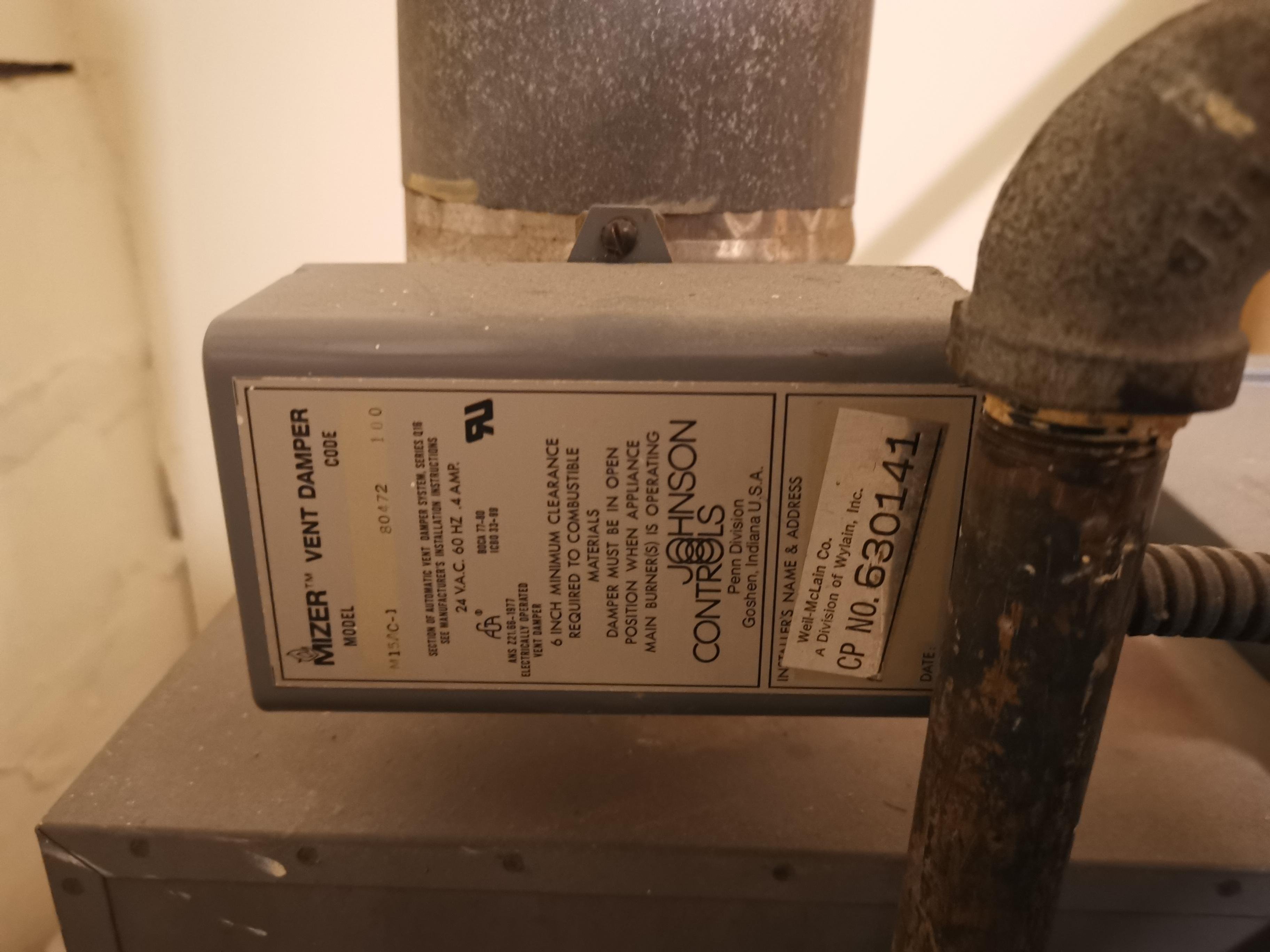
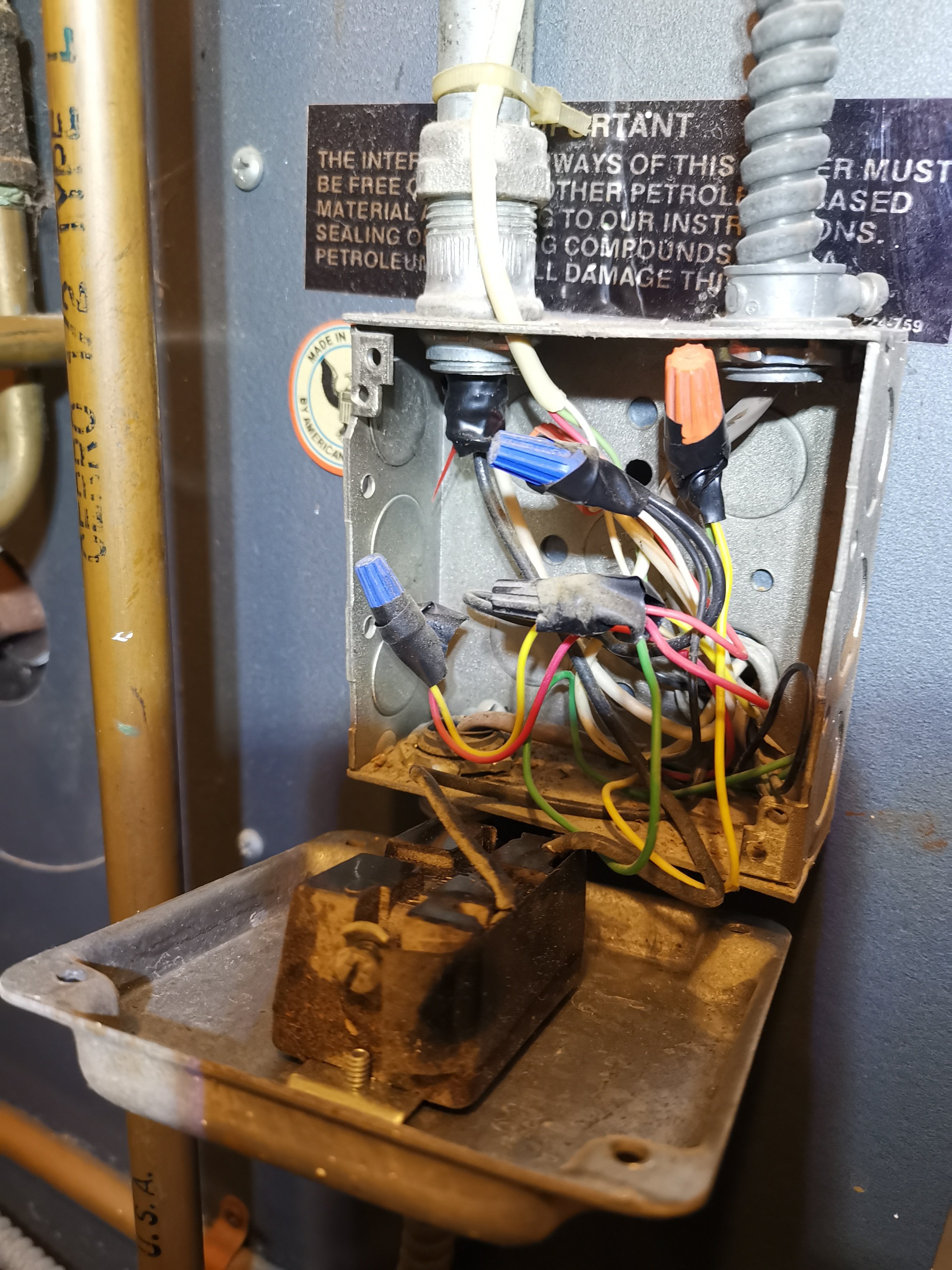
The other side of the transformer is the power switch box which connect to the pressuretrol and waterlevel safe guard. The vent damper is connected to the gas valve. However I couldn't find a spill switch. Didn't check the very bottom of the boiler though.
What could be the problem? How can I check if the individual components is getting power and works
? Maybe the pressuretrol is stuck? Is it possible there is no spill switch?
Thanks in advance for your kindly help!
Comments
-
Is the pilot lit when there is a call of heat waiting to fire up ?
There was an error rendering this rich post.
0 -
I don't think there is a pilot fire constantly on. When it's working and when heat is called, the unit will make clicking sound like a gas stove and after a while the fire will start.
Right now nothing happens when heat is called.
0 -
Perhaps a silly question: is the boiler getting electric power at all?
Br. Jamie, osb
Building superintendent/caretaker, 7200 sq. ft. historic house museum with dependencies in New England0 -
The buzz is your 24v relay that is activated. Chances are either the ignition module has locked out due to no flame detection (dirty flame rectification detection probe?), or There is a break in the gas valve circuit (e.g. the damper open proof switch is open, or high pressure lim is tripped, or flame rollout fuse blown, etc. ) It's best to look at the wiring diagram to see what safetys you have and check each one to see which one is open in the gas valve circuit. IF one is open, a qualified person should find the reason why and fix the problem FIRST before operating boiler!
0 -
Is the vent damper open? The shaft will be parallel with the flue pipe if open.
You have 26 vac at the transformer, but the switch looks like is off.
I assume the Red light would be on if low water.
0 -
Vent damper is closed.
Do you mean the main power switch? Yes I turned it off and on a few times for testing. In the photo it's off.
The Red light on the waterlevel guard is off.
0 -
check each safety with a 24vac voltmeter. should be 0v across it if it is closed. my bet is on the vent damper or its end switch.
0 -
With the thermostat raised, what reading do you get across R and Y? It should be 0 volts.
Try splicing together the wires with the Blue wire nuts.
That bypasses the thermostat and wiring to the thermostat. If it fires, then the Google Nest (the one you know works) doesn't work. I assume only R and W are connected?
The Pressuretrol looks like its wired line volt, so if that was open, I don't think you'd get 24 volts at the transformer.
If you get 0 volts across R and Y, then follow the Yellow wire on Y down to wherever it goes. And so on.
0 -
i'm not sure what is low energy and what is line voltage, they need to trace wires because the vent damper looks like it is line voltage but it clearly says 24vac on it. looks like they used a lot of flex on the low energy wiring too.
0 -
I haven't connected or tested any thing else except the voltage between R and C on the transformer which is 26 V, because the wiring is confusing to me.
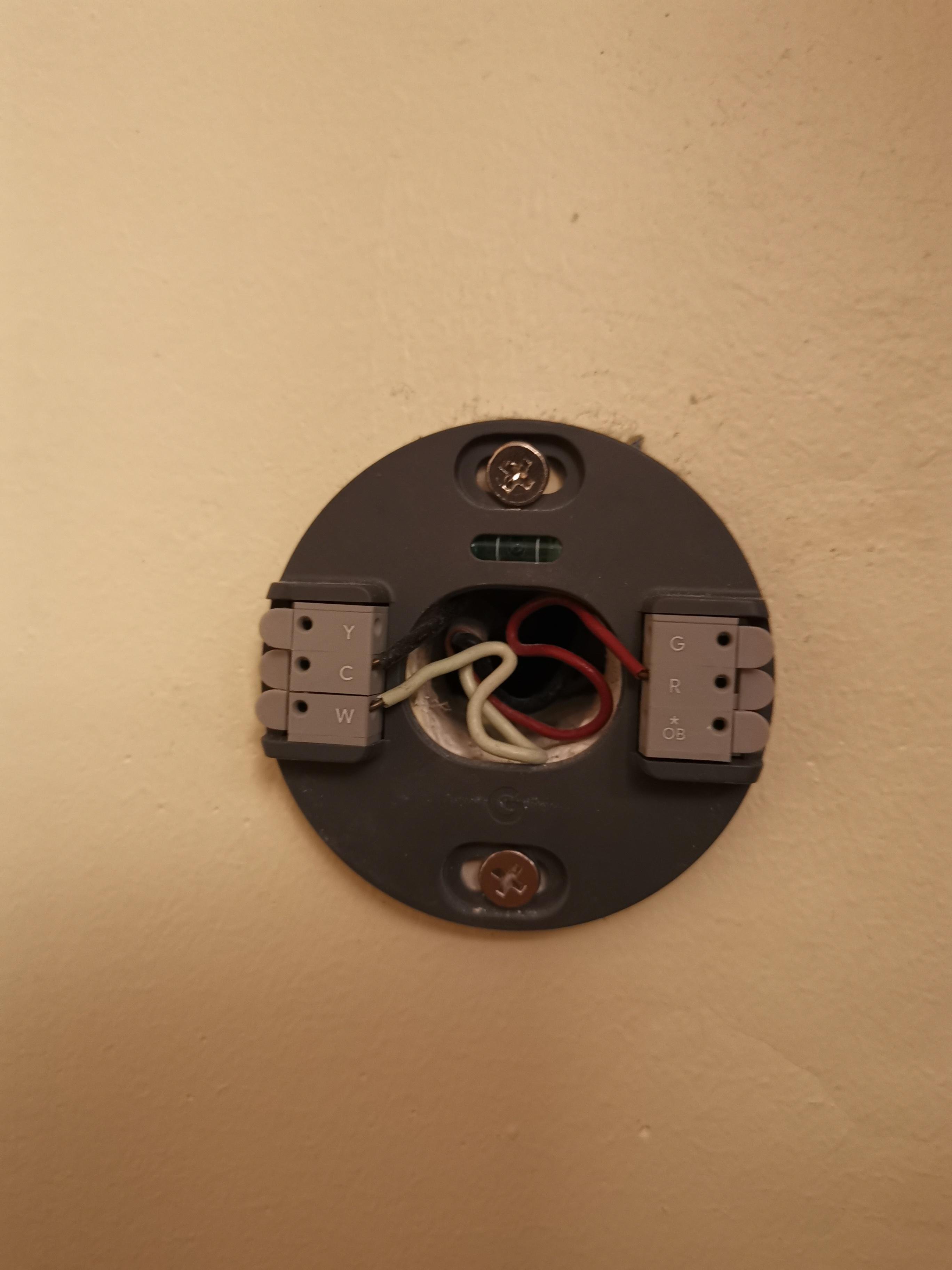
The google nest thermostat was taken from next door neighbor. We both have the same thermostat, also the wiring on the two thermostats are same as shown here, R, C, W are wired.
However on the transformer the W terminal and the center terminal are not wired to anything.
If you may, please let me know what are Y and W? I'm pretty sure R is Hot for power and C is Common?
So I should :
- test the voltage between R and Y without disconnecting anything.
- Splicing together the blue wire nuts (or use a wire to jump between R and Y should do the same thing?)
I don't know how the pressuretrol is wired but my understanding is that it should be on the same safety device chain? Do you mean if it's wired at 120 Volts then it is not the issue here because the transformer is working?
Thanks!

 0
0 -
How do I do that though? Can I jump some terminals to narrow down the issue? Thanks!
0 -
I'm a little confused but I guess you two are talking about what voltage goes to the vent damper and the pressuretrol.
The vent damper is connected only to the gas valve which gets power from the transformer so it has to be 24 V, I think.
Not sure about the pressuretrol and waterlevel safety, I think I'll open the switch box and peek inside.
Thanks!
0 -
The low water control and pressure control are NOT the problem. They are wire in the 120 volt supply. You have power on R & C from the transformer so the line voltage is good.
On a call for heat you should get 24volts between C & Y
Jumping the wires that @HVACNUT mentioned (two blue wire nuts) will bypass the thermostat.
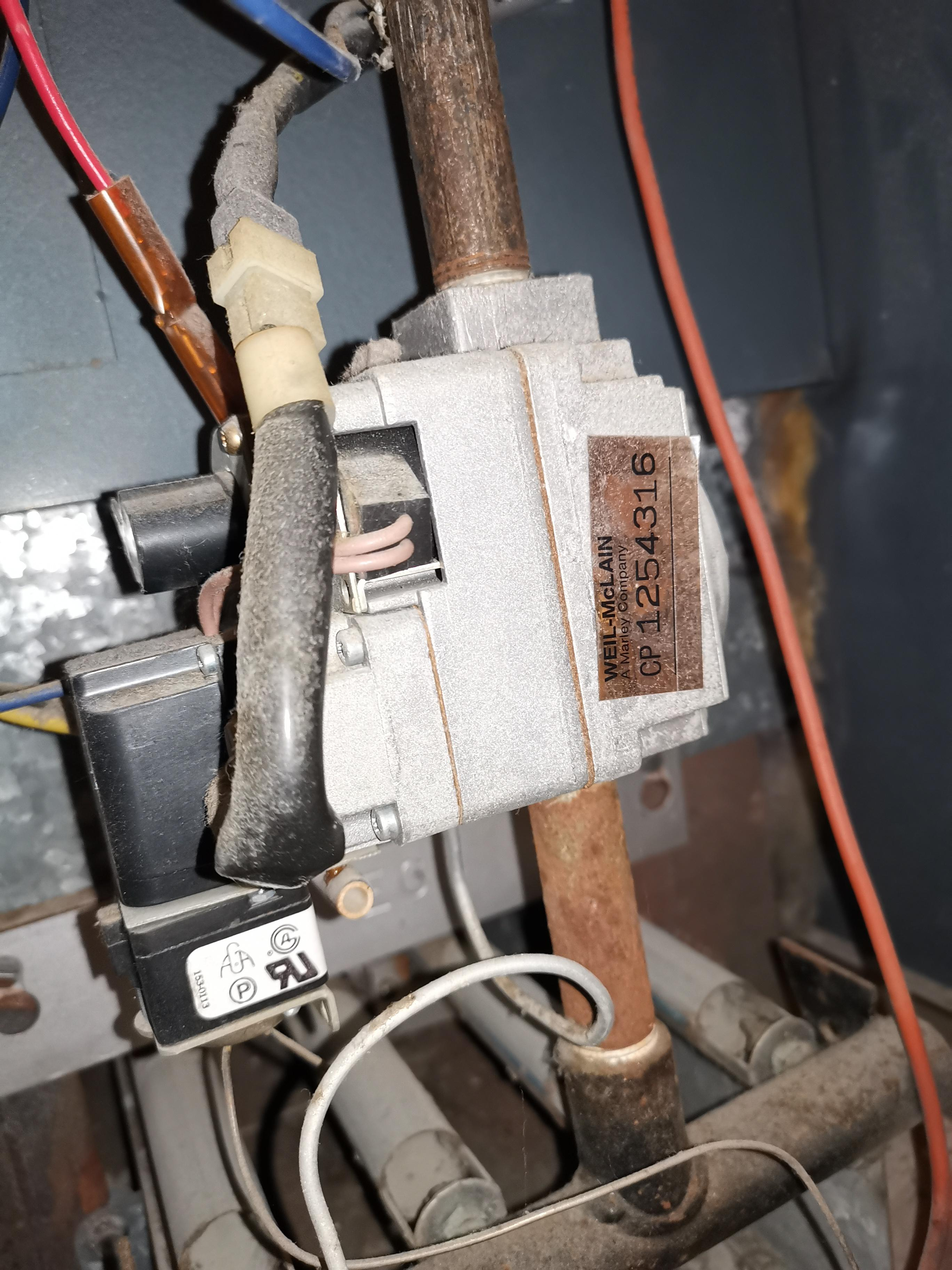
The wire thtat you show "under the boiler" is that the heavy orange spark wire?
I am guess in the vent damper is the issue.
Take the cover off the vent damper and snap a picture.
The Damper is low voltage.
0 -
if the control is closed you will read 0v across it. if the control is open you will read 24vac or 120vac across it depending on what circuit it is in.
0 -
Got it. Thanks!
0 -
The wire "under the boiler" is a heavy orange wire and i think it is the spark wire.
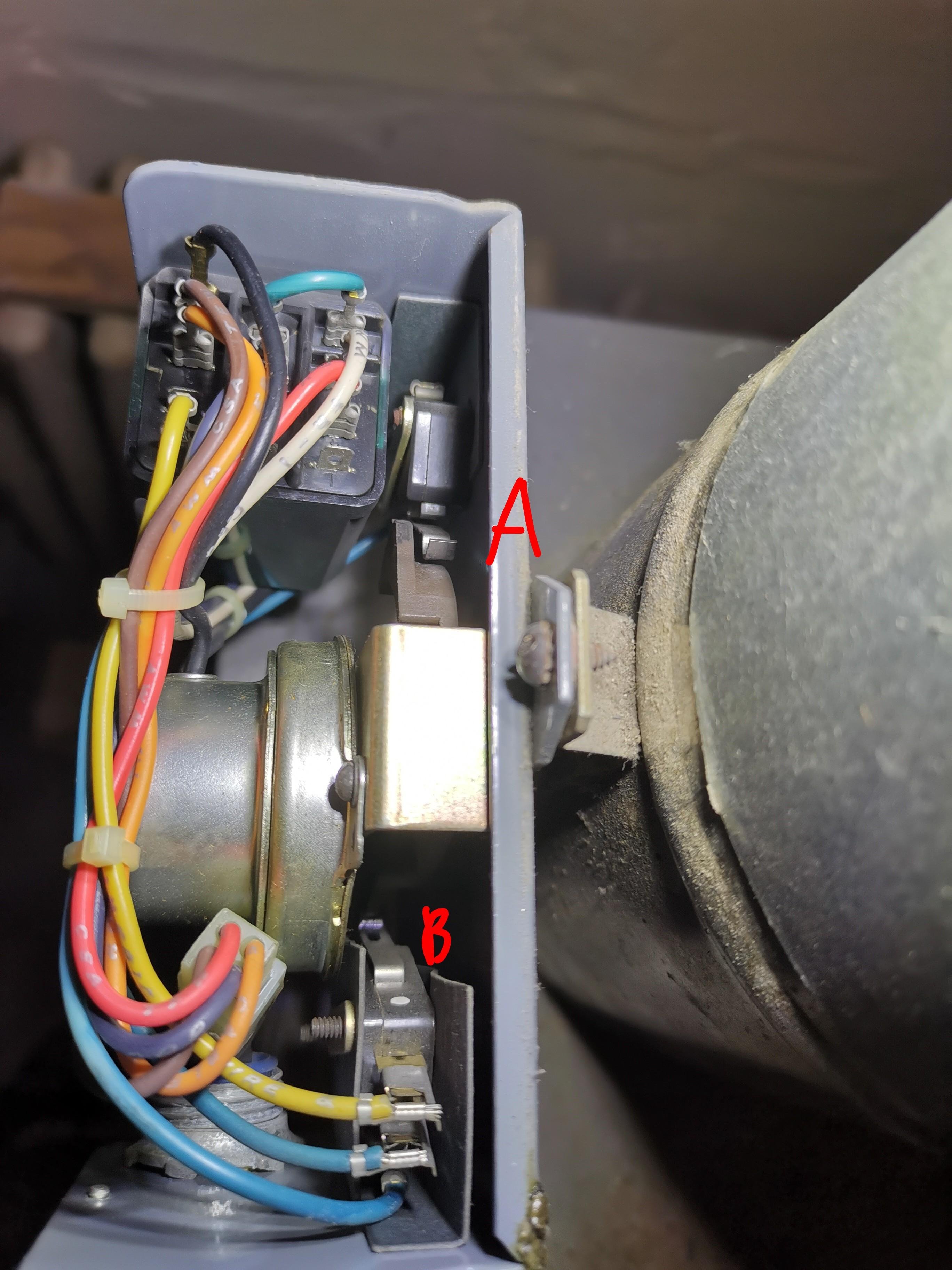
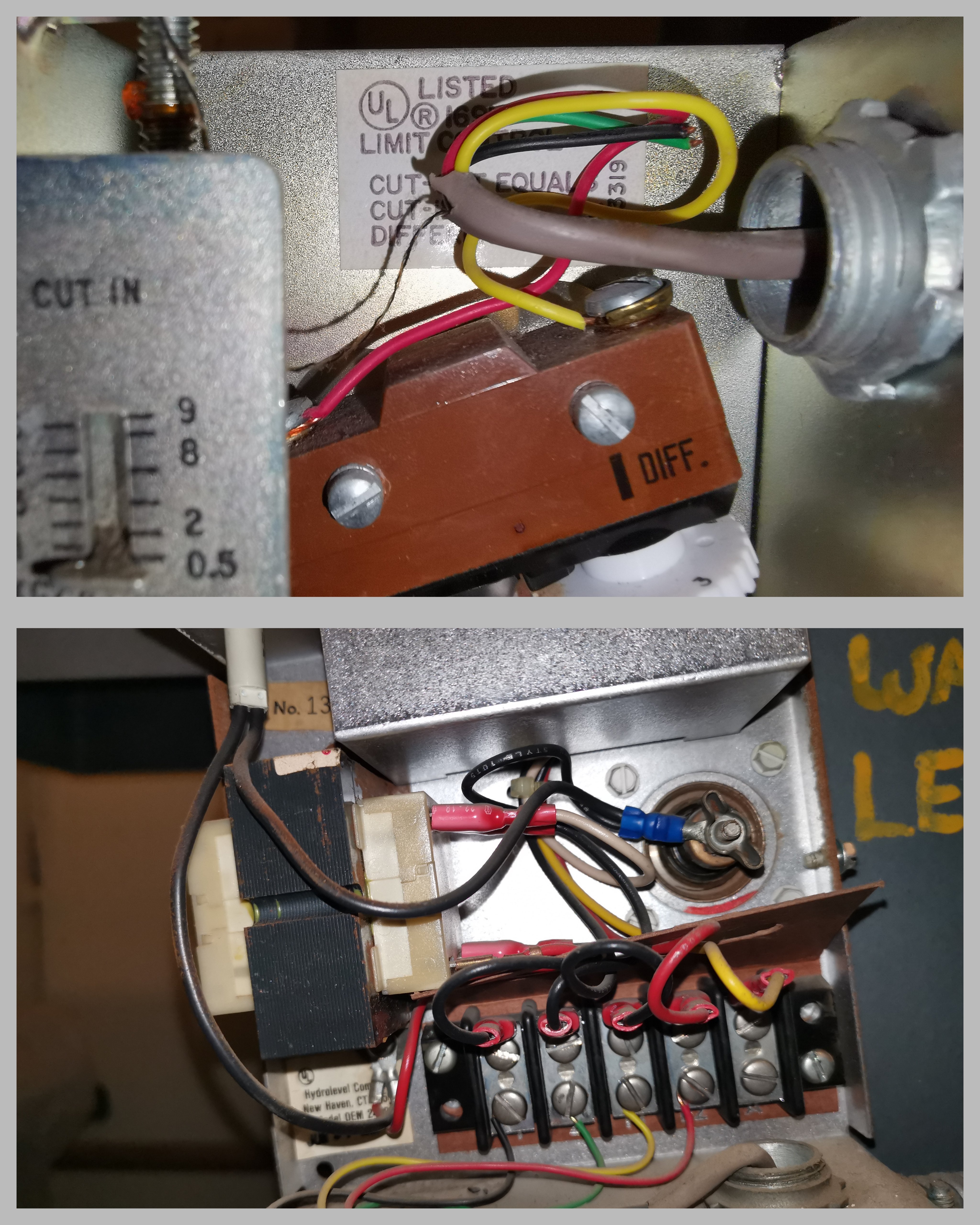
Here are pictures of new voltage test results and the vent damper insides. There are 2 spring contacts that would move if the motor turned. I marked them A and B. I'm thinking to push these 2 contacts temporarily when heat is called and see if the boiler try to fire up.
Edit: a little googling suggest that the switch B is to stop Motor once the vent is fully open, at the same time switch B will be closed to signal Gas valve to fire up. Is this correct?
Thanks!
 0
0 -
is r-y connected to r-w on the thermostat?
0 -
Not sure what you mean but this is the thermostat where R, C, W are wired, while on the transformer R,C, Y are wired.
 0
0 -
are these the thermostat wires in to the boiler? If so, why are they different colors?
 1
1 -
@Daboosa , have you tried jumping the wires with the Blue wire nuts?
Your drawing shows Yellow off the transformer going to the gas valve. It shouldn't go directly to the gas valve. It should go through safeties, the Pressuretrol, then to the vent damper. Once the damper is fully open, it sends 24 volts to the gas valve.
Is there a wiring diagram on the inside cover? Your system might be old enough where there's no Rollout or Spill switches, so there's not much to troubleshoot. If you think the Pressuretrol is low voltage, manually close the contacts if not already. Could be a clogged or water in the pigtail. I'd rather you tried that before messing with the damper.
Even on the WM app, I can't find a wiring diagram for your boiler. It came as a seperate supplement to the install manual.
0 -
Good question and I don't know. My guess is that the 3 wires through the hole go out to the google nest thermostat, R to R, C to C, but Y to W.
0 -
I haven't jumped it yet. Will try later. I understand now that it bypass the thermostat and directly call for heat by connecting R (hot) and Y(on safety chain).
The Yellow wire connects to gas valve, but it's possible that it gets wired inside the gas valve unit to go through the vent damper first. The vent damper is wired only to the gas valve, nothing else, inside a coil pipe. As some people pointed out, the pressuretrol and water level guard are probably wired on the 120V side of the transformer to cut power to the transformer if safety measure is not satisfied. Since the transformer has 26V, it doesn't look like it's the issue of pressuretrol or waterlevel guard.
No wiring diagram anywhere, inside or out. There's a warning sign inside the cover saying "installation is not complete if wiring diagram is not attached here", and it's not attached there…
What still confuses me is how exactly are the gas valve/ignition/vent damper wired through R/Y/C, and why does R-Y measure 26V?
0 -
Could be wrong but it looks to me like the Ptrol and the LWCO are wired in the 120v before it powers the transformer.
0 -
Update:
I jumped the R and Y on the transformer and the damper motors turned and boiler started to fire up!
I guess I'll first clean the contacts and redo the wire nuts and see if that works.
I'm still confused about a few things, like why is there a wire between R on transformer to the gas valve, and why does R-Y measure 26V with and without heat calling.
Thanks everybody for the help! Wish someone can answer my confusing too!
0 -
you need to trace what is connected to r and y from the junction box and figure out how that gets to the thermostat.
you can try jumping r and w at the thermostat and see if the boiler fires but i suspect there are safeties or something else in between
0 -
You are right. While cleaning i opened the junction box. The pressuretrol and water level guard are actually wired to the 24V ends. So I'm testing them now.
Must be one of the two.
 0
0 -
Why they gotta trick us like that? Now I'd look at the pigtail.
R goes TOWARDS the gas valve, but it goes past it to the vent damper. There's always 24 volts to the damper circuit board. Yellow on the transformer has 24 volts with a call for heat only after its proven the Pressuretrol and LWCO are closed. From the Y terminal on the transformer, the yellow wire also goes TOWARDS the gas valve, but it goes instead to power the vent damper open. Once the damper is proven open by the end switch you pointed out, it sends 24 volts to the gas valve. It would be nice to see it pass through Rollout and Spill switches before it gets to the gas valve.
 1
1 -
I'll clean the pressuretrol pigtail and and LWCO probe tomorrow. They haven't been cleaned for at least 5 years i think.
I tried jumping the 2 terminals on the pressuretrol while calling heat and boiler didn't fire up so it's probably not the pressuretrol. I'll still clean it.
The LWCO has too many wires though, not sure what to jump. It's warning light is off though. Is it possible that a dirty probe would keep the circuit open even though low water light is off? I don't really know how it works.
Judging by the number of wires the pressuretrol doesn't have constant 24V but the LWCO does?
 0
0 -
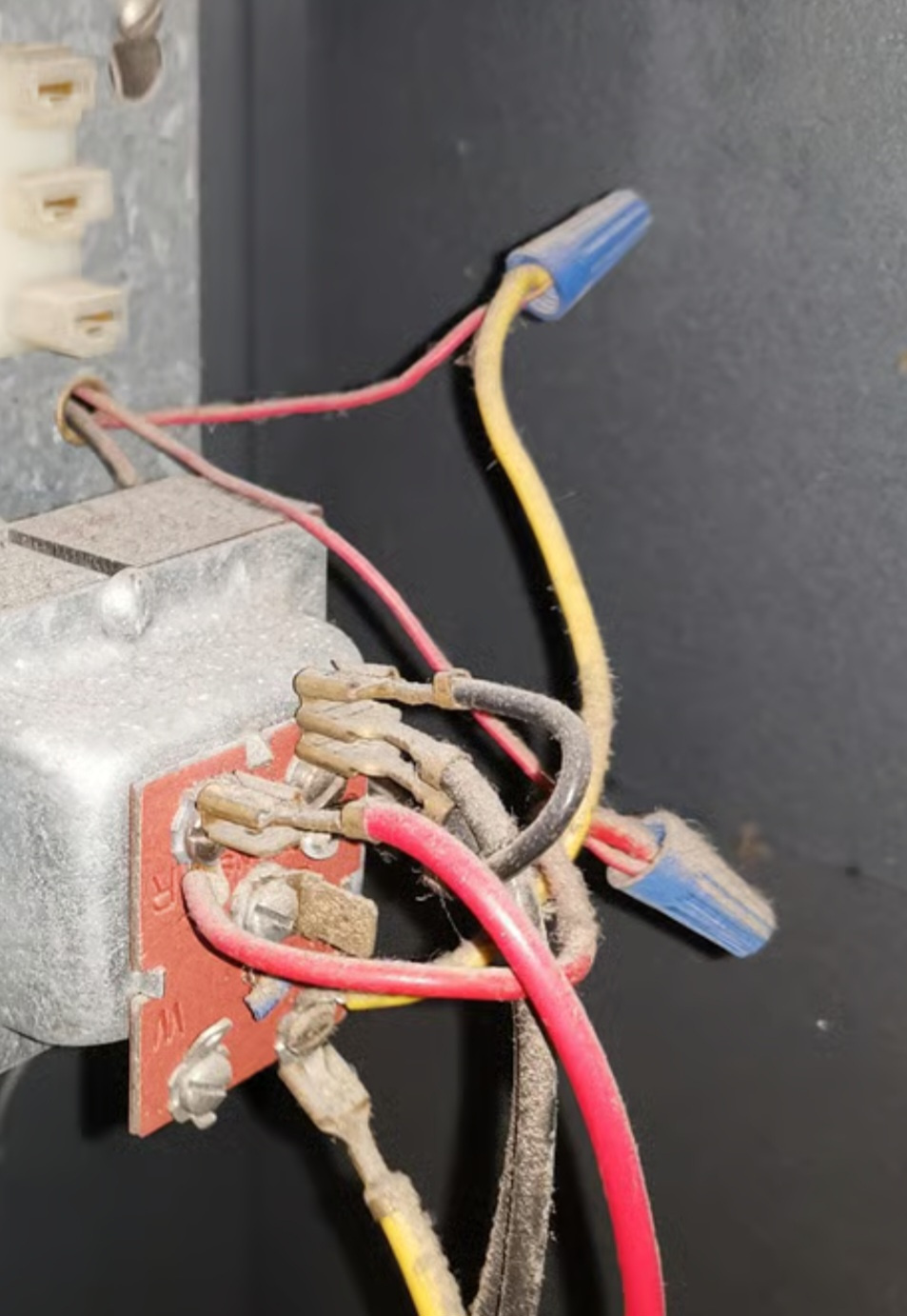
that's a lot of wire. and electrical tape
0 -
the lwco usually has a constant 24v or 120v supply to power the electronics
the pressuretrol is just a switch
 1
1 -
on the lwco i think black and green are power and yellow and red are the burner safety.
this does not have an auto feeder?
0 -
Yeah my brain refused to work when seeing those wires.
I also think the yellow and red is the safety circuit on the lwco because that's the color for the 2 wires on pressuretrol. I'll try to trace it tomorrow.
It does not have auto water feeder. I need to add some water manually about every 2 weeks if it's constantly running.
0 -
if that 5th terminal on the lwco is the same as current models it is for a valve to add water which is why i asked about an auto feeder.
0 -
I jumped the red and yellow wires on the water level guard and the boiler fired up. Now just cleaning or replacement.
Thanks everyone for the help! I learned a lot and finally figured out how this unit works.
Still couldn't find a spill switch though. Got to keep that in mind.
I traced all the circuits and drew a diagram for future reference. Whoever wired this thing was trying to confuse people with wild color switching.
 0
0 -
at least they used like 5 wire multi color cable instead of 10 pieces of black zip cord or red and white 2 conductor wire.
is there power to the first 2 terminals of the lwco?
0 -
looking at your picture, it looks like that model might be powered by 120v, see if it does indeed have 120v, there may be an additional 120v safety that is keeping it from being powered. just make sure it and the pressuretrol work, don't want to melt down the boiler.
0 -
older boilers did not have rollout or spill switches.
0 -
Forgot to test it but it must have power. The wires came from the same wire nuts that goes to the thermostat.
New issue is that the water probe is seized, or very tight. I don't have experience to tell so soaked the threads with PB blaster oil and waiting.
0 -
i'm not sure if it is powered off the 24v or the 120v since there is a transformer in there. i know there are 24v and 120v versions
0 -
"Forgot to test it but it must have power."
Wires can break underneath wire nut or may never been twisted together correctly in the first place.
Test, don't assume.
National - U.S. Gas Boiler 45+ Years Old
Steam 300 SQ. FT. - EDR 347
One Pipe System0


Categories
- All Categories
- 87.6K THE MAIN WALL
- 3.3K A-C, Heat Pumps & Refrigeration
- 59 Biomass
- 429 Carbon Monoxide Awareness
- 124 Chimneys & Flues
- 2.2K Domestic Hot Water
- 5.9K Gas Heating
- 119 Geothermal
- 168 Indoor-Air Quality
- 3.8K Oil Heating
- 78 Pipe Deterioration
- 1K Plumbing
- 6.6K Radiant Heating
- 394 Solar
- 15.9K Strictly Steam
- 3.5K Thermostats and Controls
- 56 Water Quality
- 50 Industry Classes
- 50 Job Opportunities
- 18 Recall Announcements