Well color me impressed! (LONG post)

I recently stumbled across a reference for use of a zone relay board to have multiple zone valves control the call to heat on a boiler, providing isolation of the two low-voltage circuits. FYI I have a single circulator with three zone valves (each with its own thermostat).
HIstory: in 2019, nine years after installing the boiler, one morning the boiler was not running. The logic board was dark, long story short I found that the boiler's transformer was failing on a call to heat. I determined that the best approach was to isolate the zone valve low voltage circuit from that of the boiler, which I did with a simple relay. This failure was confusing to me, since I had followed the WR instructions, and the boiler had worked fine for years.
I could not remember where I read about the zone relay board, so I decided to ask Gemini (Google's AI interface). I was amazed at the response. It was disconcerting to have Gemini initially recommend the wiring setup that led to the failure in 2019, then have it recover nicely when I fed it more information.
With more info Gemini was able to more accurately assess the situation by identifying a problem with direct wiring and the 2-wire zone valves.
Note: I later asked about the source of the direct warning issue. Although the warning was NOT in any of the documentation I received with the valves, I DID find it with a Google search, WR must have updated their technical documentation.
I feel better with an understanding now of what was actually going on.
—Eric (long read below)
Q: My boiler system has three zone valves each with its own thermostat. The boiler has a contact closure for the call to heat with two terminals labelled TT. Should I use a relay board between the zone valves and the boiler?
A: This is a classic wiring question for multi-zone hydronic heating systems.
No, you typically do not need a relay board between the standard zone valves and the boiler's TT (thermostat) terminals. The zone valves themselves are designed to handle the control logic.
Here is a breakdown of how the system is typically wired and why it works:
1. 🌡️ Zone Valve Operation
Standard two-wire or three-wire zone valves (like Honeywell V8043 or similar) contain two key components:
- The Motor/Actuator: This opens the physical valve when the corresponding thermostat calls for heat.
- An End-Switch (or Auxiliary Switch): This is a simple, dry contact (a switch) that closes only after the valve has physically opened enough to allow water flow. This switch is the critical link to the boiler.
2. ⚡ Wiring the Call for Heat (TT Terminals)
The two TT terminals on your boiler are the low-voltage (usually 24V AC) input that tells the boiler: "Ignite the burner and/or run the circulator pump." The boiler will fire whenever these two terminals are electrically connected (closed contact).
- The Solution: You simply wire the end-switches of all three zone valves in parallel across the boiler's TT terminals.
3. 🗺️ How the Logic Works
- Thermostat A calls for heat: Thermostat A powers the motor on Zone Valve A.
- Valve A opens: The motor opens the valve to let hot water into that zone's radiators/baseboard.
- End-Switch A closes: Once fully open, the end-switch inside Valve A closes, completing the circuit across the boiler's TT terminals.
- Boiler fires: The boiler receives the signal (closed contact) and starts the heating cycle.
- Simultaneous Calls: If Thermostat A and Thermostat B call for heat at the same time, both of their end-switches will close. Since they are wired in parallel, the circuit to the TT terminals is still closed, and the boiler still fires.
Scenario | Zone A End-Switch | Zone B End-Switch | Boiler TT Circuit Status |
|---|---|---|---|
Zone A heating | Closed | Open | Closed (Boiler Fires) |
Zone B heating | Open | Closed | Closed (Boiler Fires) |
A & B heating | Closed | Closed | Closed (Boiler Fires) |
No zone heating | Open | Open | Open (Boiler Off) |
4. ⚠️ When Would a Relay Board Be Used?
A separate relay board (often called a Zone Control Panel or Zone Controller) is typically used in two main situations, but often not strictly necessary for just three zone valves:
- To Manage Multiple Pumps: If your system had three circulator pumps (one for each zone) instead of three zone valves and a single main pump, the relay panel would manage which pump to turn on.
- To Simplify Wiring and Troubleshooting: A dedicated Zone Control Panel offers a clean, central point for all the wiring and often includes indicator lights for which zone is active, making installation and maintenance easier. If you plan to expand the system later, this is a good investment.
Conclusion:
For three standard zone valves, the most straightforward and traditional method is to wire the end-switches directly in parallel to the boiler's TT terminals. You can buy a simple zone control panel for convenience, but it is not technically required to make the system function correctly.
Do you know the make and model of your three zone valves, or would you like a detailed wiring diagram for connecting the three end-switches to the boiler's TT terminals?
Q2: The zone valves are White Rogers 2-wire model 1361. I originally wired them according to their specification but then during one heating system I found that the boiler transformer was failing. So I isolated the zone valves using a single relay.
A2: That's a very helpful piece of information. The White-Rodgers 1361 is a specialized two-wire valve, and your experience with the failing transformer points to a common issue with that style of valve when wired directly.
The fact that you already installed a single relay to isolate the zone valves from the boiler's TT terminals means you have already implemented the correct and safer long-term solution for your particular setup.
💡 Why Your Relay Solution is Best
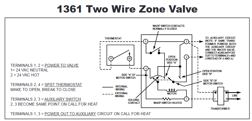
The White-Rodgers 1361 zone valve is a 2-wire valve, but it acts like a 3-wire by using a rotating switch and a warp heater to regulate its position.
The key terminals on the 1361 are:
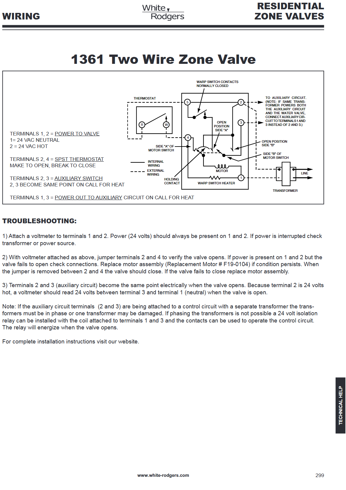
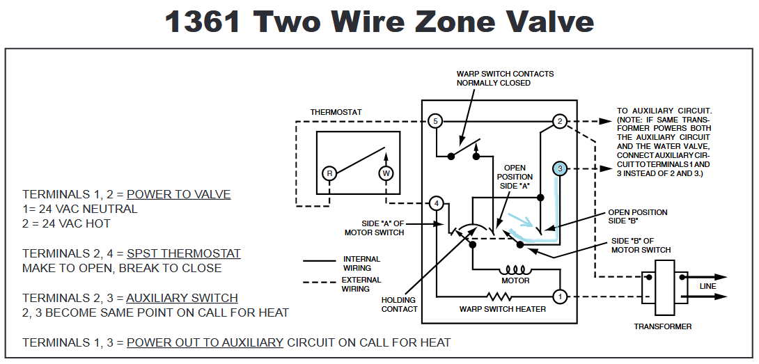
- Terminals 1 & 2: 24 VAC Power from the transformer.
- Terminals 2 & 4: Thermostat connection (closing this circuit calls for heat).
- Terminals 2 & 3: The Auxiliary/End Switch that closes when the valve is open.
Crucially, on the White-Rodgers 1361, the auxiliary switch (Terminals 2 & 3) is NOT a dry contact. Terminal 3 becomes energized (carries 24 VAC power) when the valve is fully open, and Terminal 2 is the common/neutral wire from the transformer.
The Risk of Direct Wiring (What likely failed your transformer):
If your boiler's TT terminals are also fed by a 24 VAC transformer (which is very common), and you wire the 1361's energized Auxiliary Switch (Terminals 1 & 3, or 2 & 3 depending on which wire is the common/hot) to the boiler's TT terminals, you are effectively connecting two different transformer circuits together.
- This can create a dangerous "backfeed" situation.
- The phase relationship between the zone valve transformer and the boiler control transformer may clash, leading to high circulating current that can overload and eventually destroy one or both transformers.
✅ Conclusion: Keep the Relay
You should absolutely continue to use a relay (or a zone control panel) to isolate the zone valves from the boiler's TT terminals.
Your current single relay acts as a buffer:
- Zone Valves Call for Heat: When any of the three zone valves opens, its energized auxiliary switch (Terminals 2 & 3) sends 24 VAC to the coil of your isolation relay.
- Isolation: The isolation relay energizes.
- Boiler Call: The dry contacts on the isolation relay close, completing the circuit across the boiler's TT terminals.
This setup protects your boiler's internal transformer/control circuit from the potential power conflicts of the energized White-Rodgers auxiliary contacts.
If you have all three zone valve end-switches wired in parallel to the coil of that single relay, your system is correctly protected and optimized for those specific White-Rodgers 1361 valves.
Comments
-
what?
 1
1 -
Google AI
Dazzle them with brilliance
Baffle them with B$
😁
0 -
I don’t think I’ve ever seen a boiler’s transformer damaged by a compromised zone valve end switch. It’s just one leg of the transformer and it won’t short.
Personally, I use a zone valve control for ease of wiring and troubleshooting.8.33 lbs./gal. x 60 min./hr. x 20°ΔT = 10,000 BTU's/hour
Two btu per sq ft for degree difference for a slab

 5
5 -
In addition, I'd add that relay boxes offer fuse protection, pump exercise, priority,RWC t-stat connections
 Bob "hot rod" Rohr
trainer for Caleffi NA
Living the hydronic dream1 -
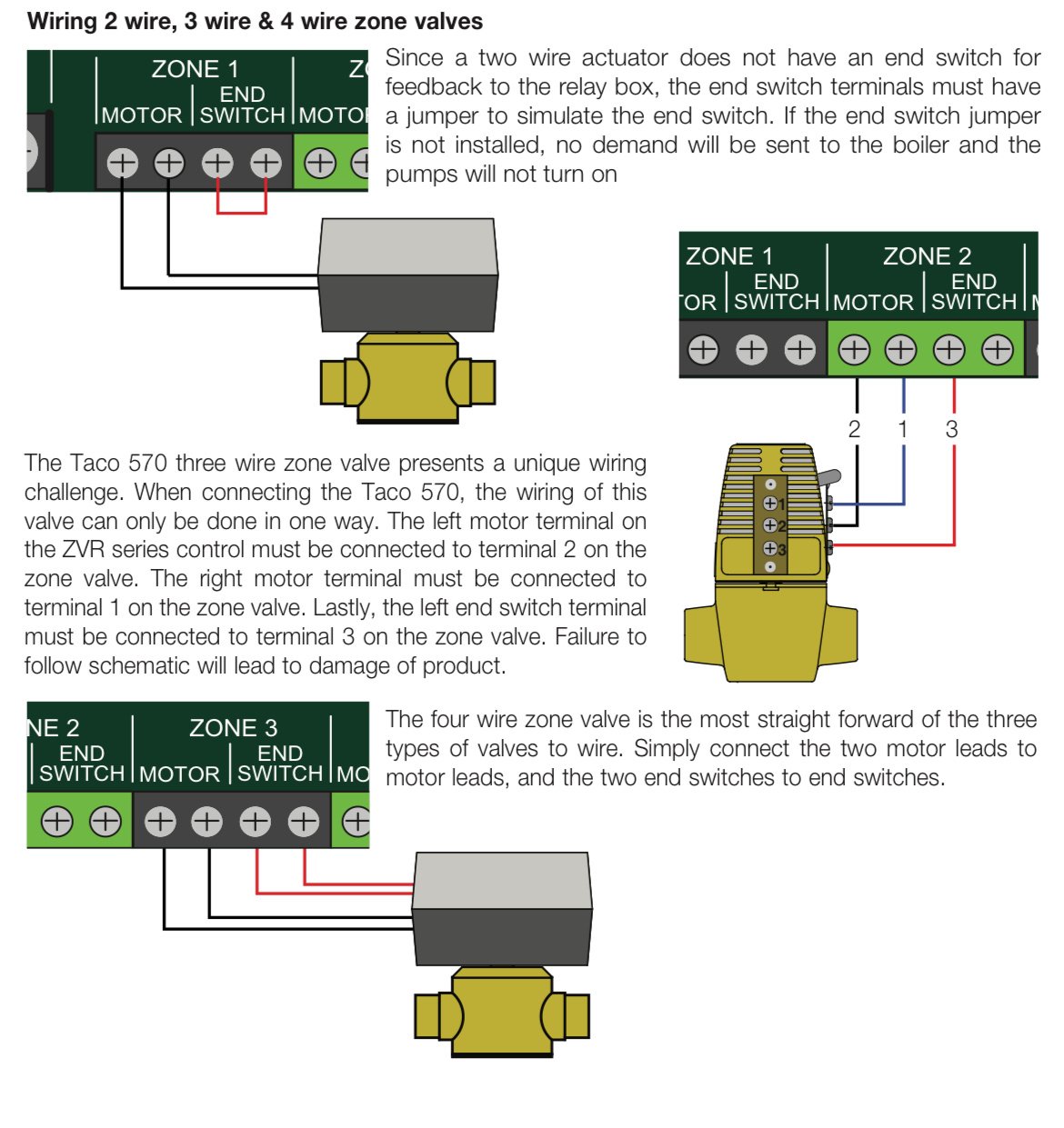
The Taco valve like the 573 are also 3 wire. As taco explains it lets say your going to T & T on an oil boiler on a call for heat to start the burner. T & T on the primary control also is fed by the small transformer on the cad cell relay so if the end switch on the valve (like a Taco) the end switch will also be hot from the zone valve transformer.
You will have two transformers intermingled, but it is not an issue if wired properly. See the attached. Page 3.
Personally, I would rather have relays to avoid confusion and miswiring.
0 -
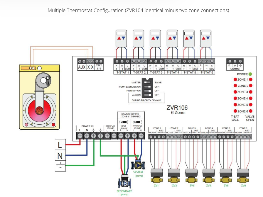
on the Caleffi ZRC the 573 wires like this
 Bob "hot rod" Rohr
trainer for Caleffi NA
Living the hydronic dream0 -
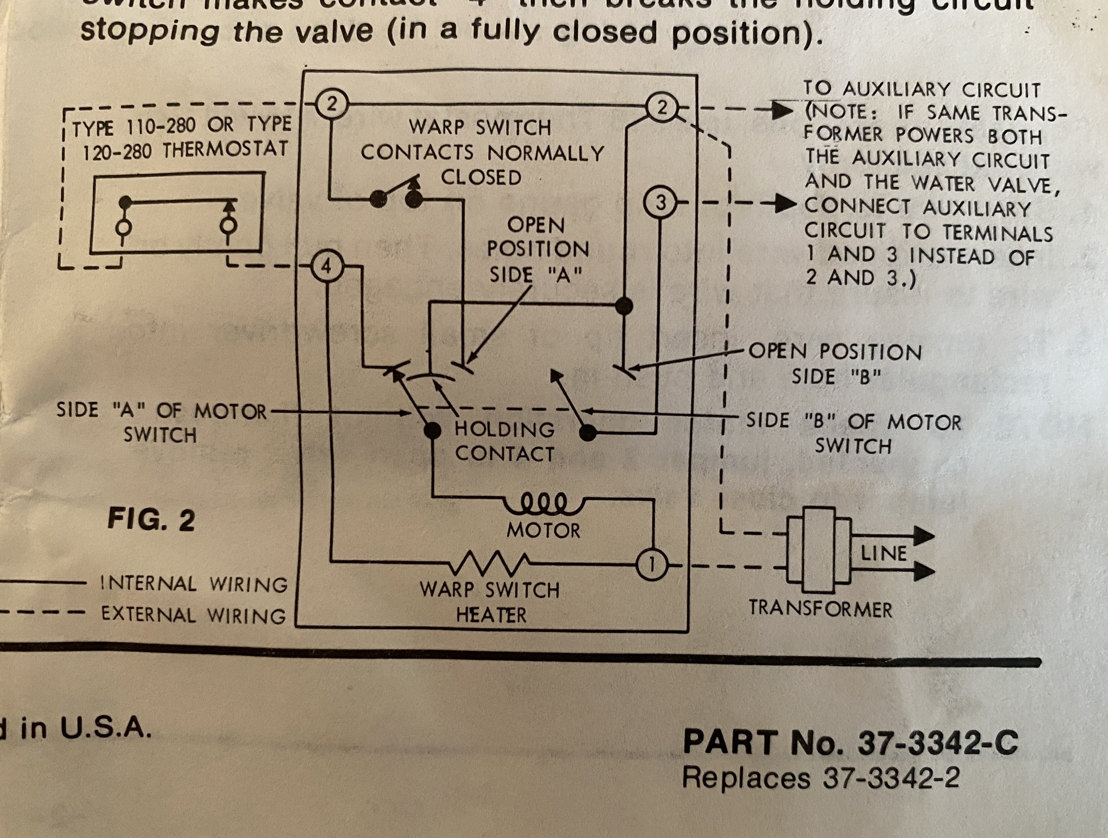
Here is the text from White Rogers:
Note: If the auxiliary circuit terminals (2 and 3) are being attached to a control circuit with a separate transformer the transformers must be in phase or one transformer may be damaged. If phasing the transformers is not possible a 24 volt isolation relay can be installed with the coil attached to terminals 1 and 3 and the contacts can be used to operate the control circuit.
The relay will energize when the valve opens.Document is here: link
—Eric
0 -
What WR said is true if both wires of both transformers are intermingled. But as explained in the Taco brochure if only one wire is then it is not an issue.
Rib relays with the LED light or a zone panel with lights makes it easier for things not to get mis wired and makes troubleshooting easier.
0 -
dhw priority is really the only thing you need it for, the rest is mostly for organization.
is this the say something wrong and get corrected by 30 people instead of asking a question and no one answering thing?
0 -
The zone valve connection information has been out there probably for decades but folks refuse to read the instructions and/or if they do they still decide to do things wrong. Steam boiler near boiler piping is a classic example of not following instructions.
With the White Rodgers 1361 zone valve, a relay is not needed if the zone valve is wired correctly to the system and the Taco document explains why. A transformer failing after 9 years of service is most likely just a transformer failure especially if no NEW actual underlying system issue is found.
Generally transformers are very reliable, but they do fail.
Nothing wrong with isolation relays, even if you don't need them, except you have added another device to the system that can also fail.
This below is more like Lawyer CYA speak than Electrical Engineering.
 National - U.S. Gas Boiler 45+ Years Old
Steam 300 SQ. FT. - EDR 347
One Pipe System 2
2 -
@mattmia2 - Haha good point about getting responses.
No, this was me trying to be informative about an actual problem I had (multiple blown transformers), a solution to that problem (isolation relay), and how an AI program kinda/sorta got it right after some iteration.@Alan (California Radiant) Forbes - I took notes that day:
- all zones calling for heat, but no heat because transformer had blown (the one on the boiler)
- replaced transformer.
- on call for heat from zone valves, replacement transformer blew
- replaced transformer, added 3A fuse.
- on next call for heat from zone valves, fuse blew.
- replaced fuse, created call for heat by connecting the TT terminals on the logic board. Boiler fired and ran normally. Fuse did not blow.
- added relay between zone valves and TT terminals.
- on next call for heat from zone valves, boiler ran normally.
@109A_5 - can you expand that diagram to show the revision at the bottom of the page? My revision is 37-3342-C,
I did RTFM and the documentation that came with my zone valves was missing the bit you refer to as lawyer CYA stuff. Maybe instead the engineers at WR added it?
—Eric
0 -
 0
0 -
@EricPeterson No revision number.
https://s3.amazonaws.com/s3.supplyhouse.com/product_files/White%20Rodgers%20-%201361-102%20-%20Wiring%20Guide.pdf
 National - U.S. Gas Boiler 45+ Years Old
Steam 300 SQ. FT. - EDR 347
One Pipe System0 -
@EricPeterson In situations like this you have to ask 'What changed ?'. A wiring setup that lasted and worked correctly for 9 years was probably correct. Adding an isolation relay may have masked the real issue and with the added benefit of restoring proper operation.
Personally in situations like this I like to troubleshoot with a light bulb (Dim Bulb Test), no more blown transformers or fuses.
If I had to guess from here, one side of your boiler's transformer is grounded (maybe through the logic board). Due to a zone valve or zone valve wiring defect I suspect one of the terminals of the 1361 has become erroneously grounded. When the End switch (Side B) closes the erroneous ground path causes harmful current through the transformer that fails. I suspect the erroneous excessive current is made possible since the pipes going to the zone valve are connected to the boiler. With a Dim Bulb Test and a clamp on ammeter the fault current may be obvious but limited to a safe level by the use of the Lamp.
So the Lawyers and/or Engineers being made aware of a possible ground defect with their zone valve recommend the isolation relay… CYA !!! If the fault happens know one knows. CYA
In a properly working circuit (as explained in the Taco document) closing the 1361's terminals 2 to 3 should not cause any excessive (harmful) current to flow in either transformer (boiler or thermostat / zone valve power). Secondary windings of multiple transformers 'touch' all the time and it does not cause a mysterious failure unless there is a defect somewhere.
 National - U.S. Gas Boiler 45+ Years Old
Steam 300 SQ. FT. - EDR 347
One Pipe System0 -
"I did RTFM and the documentation that came with my zone valves"
I was not suggesting you did not read the manual or provided documentation and/or wired something wrong. It's just that manufactures probably see so many issues from folks that don't do it correctly that they have to make things as bullet proof as possible by any means.
Now with reading your notes above I believe there is a product defect that may eventually happen causing the issue you have experienced without the isolation relay. The isolation relay masks the eventual defect.
National - U.S. Gas Boiler 45+ Years Old
Steam 300 SQ. FT. - EDR 347
One Pipe System0 -
@109A_5 - good points all around. I did wonder if I made some change prior to the failure, but I have no recollection of this. Perhaps I reconnected a transformer to the zone valves which put things out of phase. But I am just speculating.
This issue aside, the WR zone valves have been reliable workhorses for almost 40 years. I think I installed the first one when we moved into our house in 1986.
—Eric
0 -
I am a bit puzzled by the time line.
"HIstory: in 2019, nine years after installing the boiler"
So if I understand correctly the issue was resolved in 2019 ?
And you are now just revisiting it to test the present AI resolutions for the issue of 6 years ago ?
National - U.S. Gas Boiler 45+ Years Old
Steam 300 SQ. FT. - EDR 347
One Pipe System0 -
Yes it was resolved in 2019. The AI query was because I bought a zone relay board this year but could not remember why - thinking perhaps it was for rewiring the zone valve controls I did an AI query which started me on this whole thread. I still don't remember what prompted me to buy the board. Maybe it looks like a cleaner solution than what I came up with. But somewhere in my internet browsing I encountered someone who used this board, I just lost the reference is all.
It was all fortuitous though in that I found some credible explanation for the transformer failures, but not for what caused the problem to surface in the first place.
There is one other thing that I didn't mention. On my boiler, the TT terminals are on what is called the Option Panel. These connect to a wiring harness that goes to the main logic board.
So about a year earlier, in Dec.2018, there was no response from the boiler with a call for heat. I discovered that there was a discontinuity between the Option Panel and the control board for one of the TT terminals. So I just jumpered the TT terminal directly to the control board, figuring there was something wrong with the wiring harness. It was only later, when dealing with the failing transformers, that I discovered a burnt trace on the Option Panel. So the "overload condition" or whatever apparently occurred the year before, and instead of killing a transformer, damaged a control line on a circuit board.
It remains a mystery why this happened in 2018, and why my jerry-rigged fix lasted another 12 months.
Regardless, I am satisfied that the relay solution is a long-term fix.
—Eric
0 -
The way it seems to me;
The transformer phasing does not matter since there should only be one point where the circuits from the two transformers touch, (which is this other part of WR CYA statement is just a CYA attempt in my opinion).
I believe there is a flaw or defect in one or more of your WR zone valves that intermittently grounds some part of the electrical circuit to the piping. This overloads the boiler's transformer. I suspect this probably started happening in 2018, so the defect caused trace in the Option Panel to act like a fuse. Since you made the fuse more robust it eventually started to kill the transformers.
Unwanted Intermittent connections can do some bazaar things at times, which often makes them hard to find.
Then adding the isolation relay removed the devastating effect of the intermittent grounding issue on the zone valve side of the circuit. The original defect probably still exists if you ever wanted to actually find it and solve the mystery.
National - U.S. Gas Boiler 45+ Years Old
Steam 300 SQ. FT. - EDR 347
One Pipe System0


Categories
- All Categories
- 87.6K THE MAIN WALL
- 3.3K A-C, Heat Pumps & Refrigeration
- 59 Biomass
- 429 Carbon Monoxide Awareness
- 124 Chimneys & Flues
- 2.2K Domestic Hot Water
- 5.9K Gas Heating
- 119 Geothermal
- 168 Indoor-Air Quality
- 3.8K Oil Heating
- 78 Pipe Deterioration
- 1K Plumbing
- 6.6K Radiant Heating
- 394 Solar
- 15.9K Strictly Steam
- 3.5K Thermostats and Controls
- 56 Water Quality
- 50 Industry Classes
- 50 Job Opportunities
- 18 Recall Announcements