Advice would be appreciated

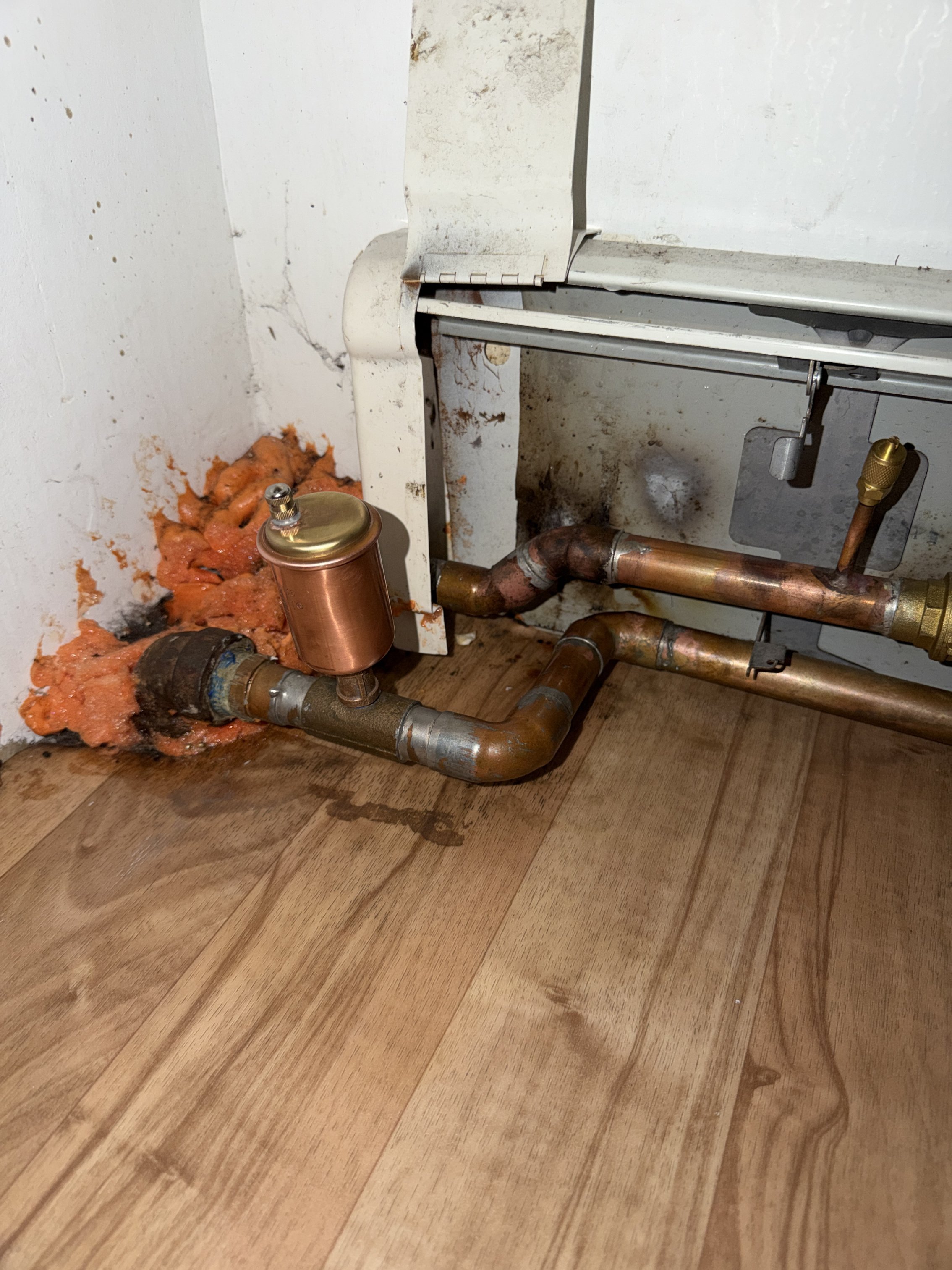
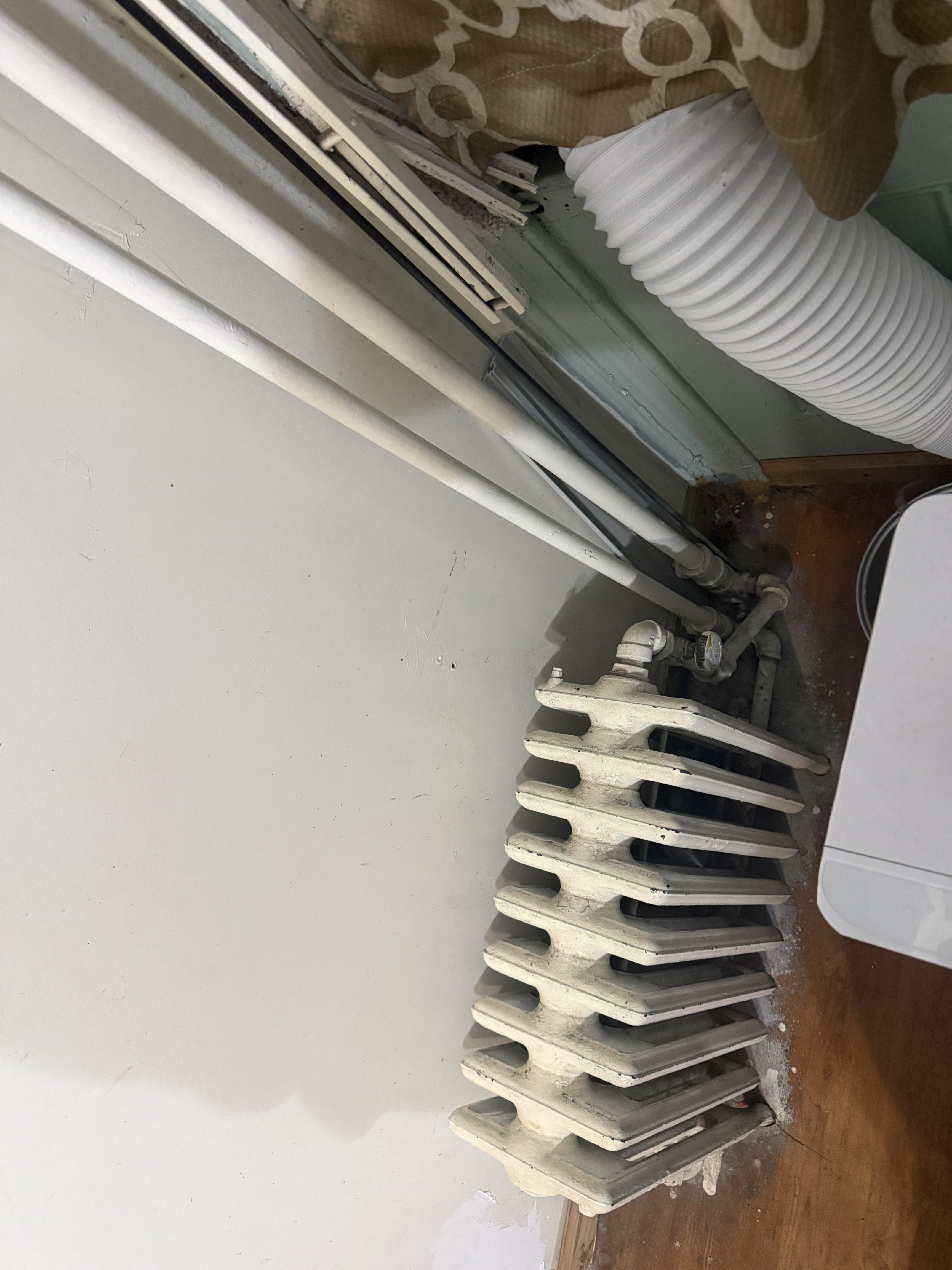
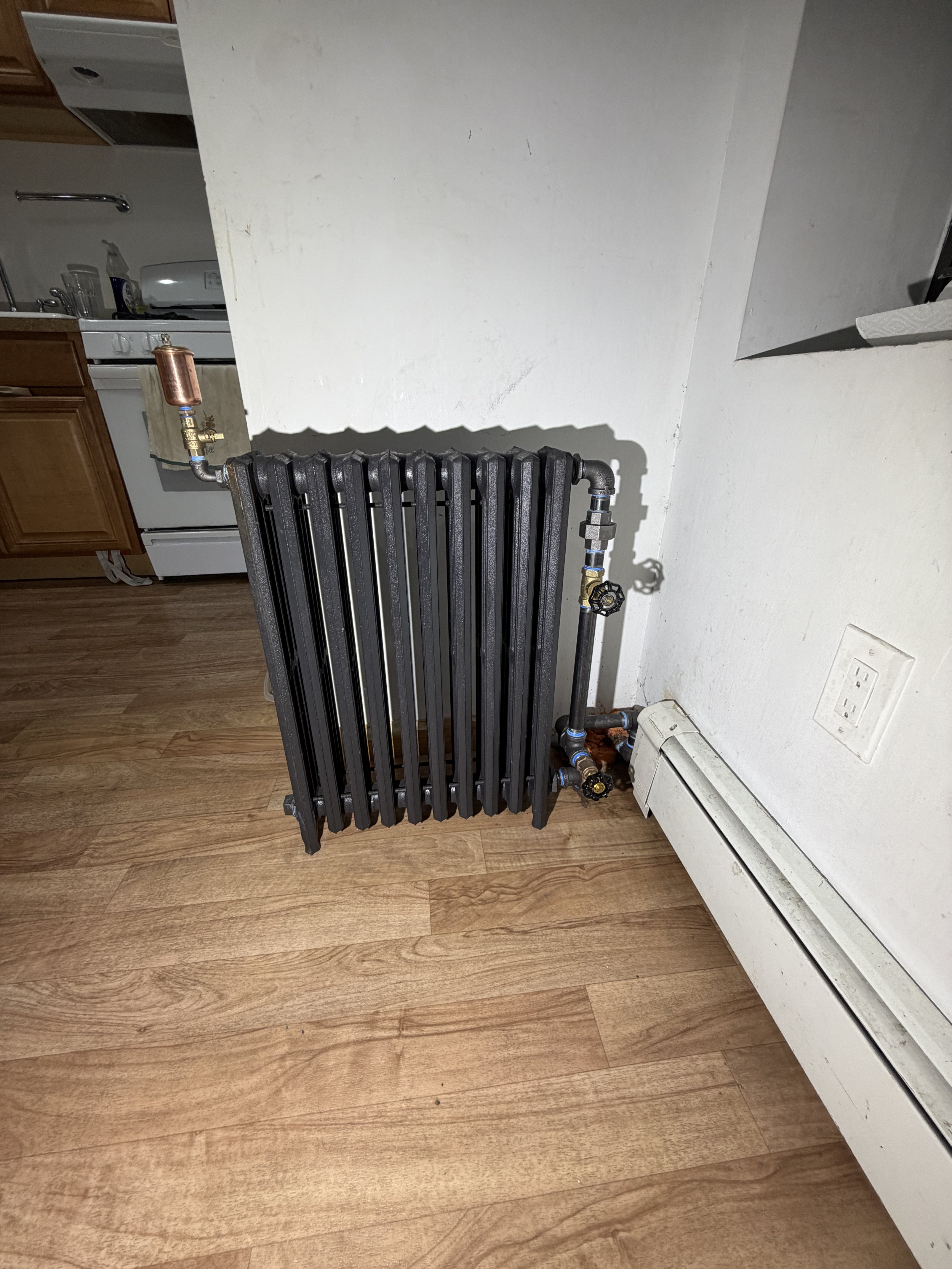
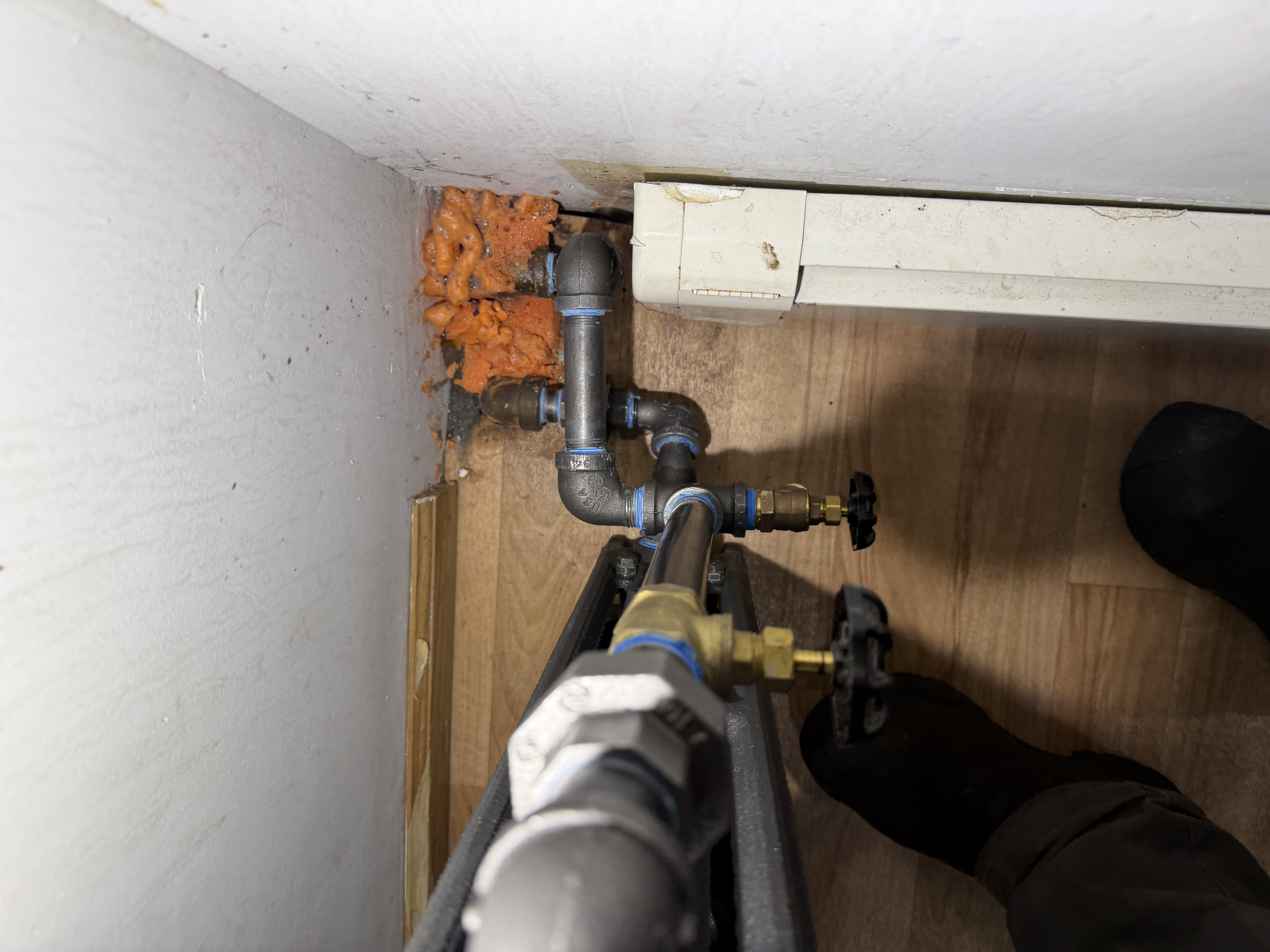
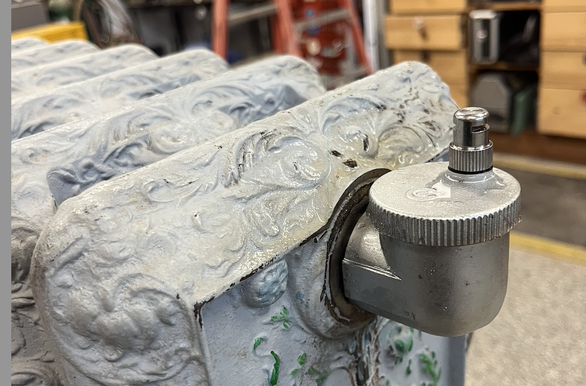
Hi, I was wondering if you guys had any answers or advice to this issue I have. The whole home heats, boiler works fine, pump works fine, system had adequate pressure. Besides this third floor baseboard radiator that is. This radiator does not get hot unless you bleed tons of water (not just air) out of it. The picture with the large cast iron radiator is on the second floor directly below the non-working baseboard. When you feel the pipes rising, the supply is hot and then just becomes ice cold. No movement of water whatsoever. I tried to throttle the ball valve on the third floor to create some type of a pressure difference and force the water to move, but idk. I also added an automatic bleed, but I doubt that will fix the issue. And no, I did not braze those ports; that was a plumber that came prior to me. Also, these two elbows that rise are the peak of this system and directly loop with each other and nothing else about six feet to the right.
Comments
-
Is there an additional set of tees feeding another radiator behind this?
You would need to choke down the flow to those radiators also.
The fintube loop has more flow resistance.
What is the pressure at the boiler? The boiler is 3 levels or more below the fin tube?
The fin tube and cast radiators are not a good blend, they heat at much different rates and will never balance properly on one zone.
Bob "hot rod" Rohr
trainer for Caleffi NA
Living the hydronic dream 2
2 -
As @hot_rod mentioned looks like two tees going through the wall to another rad.
Balancing may or may not fix this issue.
The sure fix is to get the baseboard on its own zone or repiping it to be a series loop with the baseboard first on the loop and or replace the baseboard with CI rad.
Water is taking the path of least resistance and it doesn't want to go to the third floor.
0 -
You will need to reduce the flow to any radiators on a lower floor that are on this same loop. Water is lazy, and all that pipe and the fin tube… it's going to go somewhere else unless you force it to go through the fin tube.
Keep the valves on the fin tube wide open!
Br. Jamie, osb
Building superintendent/caretaker, 7200 sq. ft. historic house museum with dependencies in New England2 -
@hot_rod no the tees are plugged off. Its just that one radiator you see. The boiler pressure is at 15 psi. Id prefer not to raise it but if need be its fine. I just changed the expansion tank and put a much larger one. The boiler is in the basement. Then there is a first second and the copper loop is on the third. So you suggest to throttle the downstairs radiator instead and leave the top floor wide open?
0 -
@EBEBRATT-Ed thank you for the response. It is only feeding that radiator on the second floor. Do you mind elaborating on how a repipe on the top floor would go? Instead of replacing it with a radiator. Id truly appreciate your input.
0 -
Thank you @Jamie Hall
0 -
That fin-tube may have just enough internal resistance in it to keep the water from circulating through it when there is an easier path elsewhere. And has anyone looked to see if someone reduced the pipe size where it comes up through the floor and connects to the fin-tube?
All Steamed Up, Inc.
Towson, MD, USA
Steam, Vapor & Hot-Water Heating Specialists
Oil & Gas Burner Service
Consulting0 -
@Steamhead it maintains the size going up. Upstairs are two elbows by 3/4. Im thinking of taking everyone’s advice and throttling the second floor radiator instead the hopes that it flows upstairs.
0 -
does water come out of that schrader that someone used instead of a bleeder?
a repipe would mean you'd have to get the pipes from the baseboard at least to the mains in the basement if not all the way back to the boiler. even if you do that because the fin tube has so little mass compare to the cast iron it won't heat evenly with the rest of the house. i doubt that it is a big enough load to put on its own zone without running in to short cycling issues. A cast iron radiator is really the right answer.
15 psig is a liitle marginal for a 3rd floor, it is possible the pressure drops and sucks air in that auto vent when the circulator is running.
it is also possible that the loop with the baseboard is the most resistance in the system and it is more than the circulator can provide.
0 -
You should put a Pressure gauge on the bleeder on the top floor and check the pressure. You can also calculate the pressure, but a gauge is better. You need 4-5 PSI at the top with the pump off. Thats the first thing to try.
If those two pipes show up in the basement and they only feed that one radiator and the Finn tube you could stick a circulator on it in the basement. Wire in a thermostat and a relay and a balancing valve on the second floor rad.
1 -
@EBEBRATT-Ed @hot_rod @Jamie Hall @mattmia2 @Steamhead
I appreciate the input from all of you. They approved my quote to change the radiator. Put in a small cast iron radiator on the loop and a globe valve to throttle its heat in case it gets a little too hot. Worked like a dream. Also have an auto air vent and a hose bib for forcing some water flow if need be in the future. I wanted to feed from the top right and pull the return from the bottom left of the rad but it was much easier this way. Also do you guys know of a sleeker or better alternative to having a bulky ball valve on the auto air vent for future service. I don’t like how large it looks. Ik Caleffi makes inline check valves for theres but I’ve heard its hit or miss.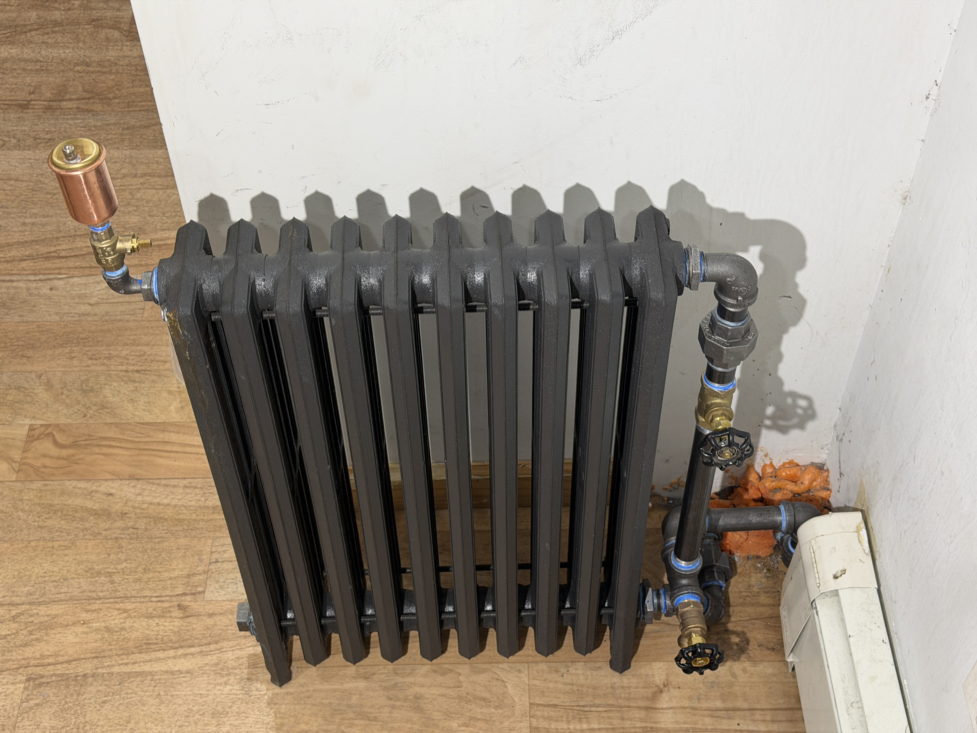
 0
0 -
That is some good pipefitting. It has a nice old-school, 'sculptural' look. I like the combination of black iron, copper and brass. Blue tape gives it a 'modern accent'.
 2
2 -
I'm not sure the float vent is needed. Couldn't just put a coin vent there? I'd be worried that something or someone is going to get fetched up on that while passing by.
Miss Hall's School service mechanic, greenhouse manager, teacher, dog walker and designated driver
 3
3 -
@Grallert third floor up. Also the top floor of this loop. There is an air scoop on the boiler but no Spyro vent. I don’t like the bulky look and I did mention it to the home owner before starting. They said it’s fine and they look the look if it means there’s no chance they would have to bleed air again. I total get what you mean tho I was nervous about it too.
 1
1 -
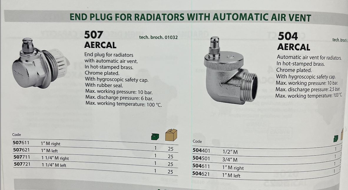
Caleffi has a few nice plated air vents for radiators, unfortunately not a U.S. product. You could find them online, maybe a UK site that ships? They come with hydroscopic caps should the valve mechanism ever fail.
They may be NPTF, but I have had them seal with some tape or hemp.
\
I'd be glad to mail to you a few hydroscopic, 3/8". These are manual, auto, or can be removed as it has a ball check in it. The top part does have a life expectancy depending on how many wet/ dry cycles. We suggest a 3 years replacement.
\
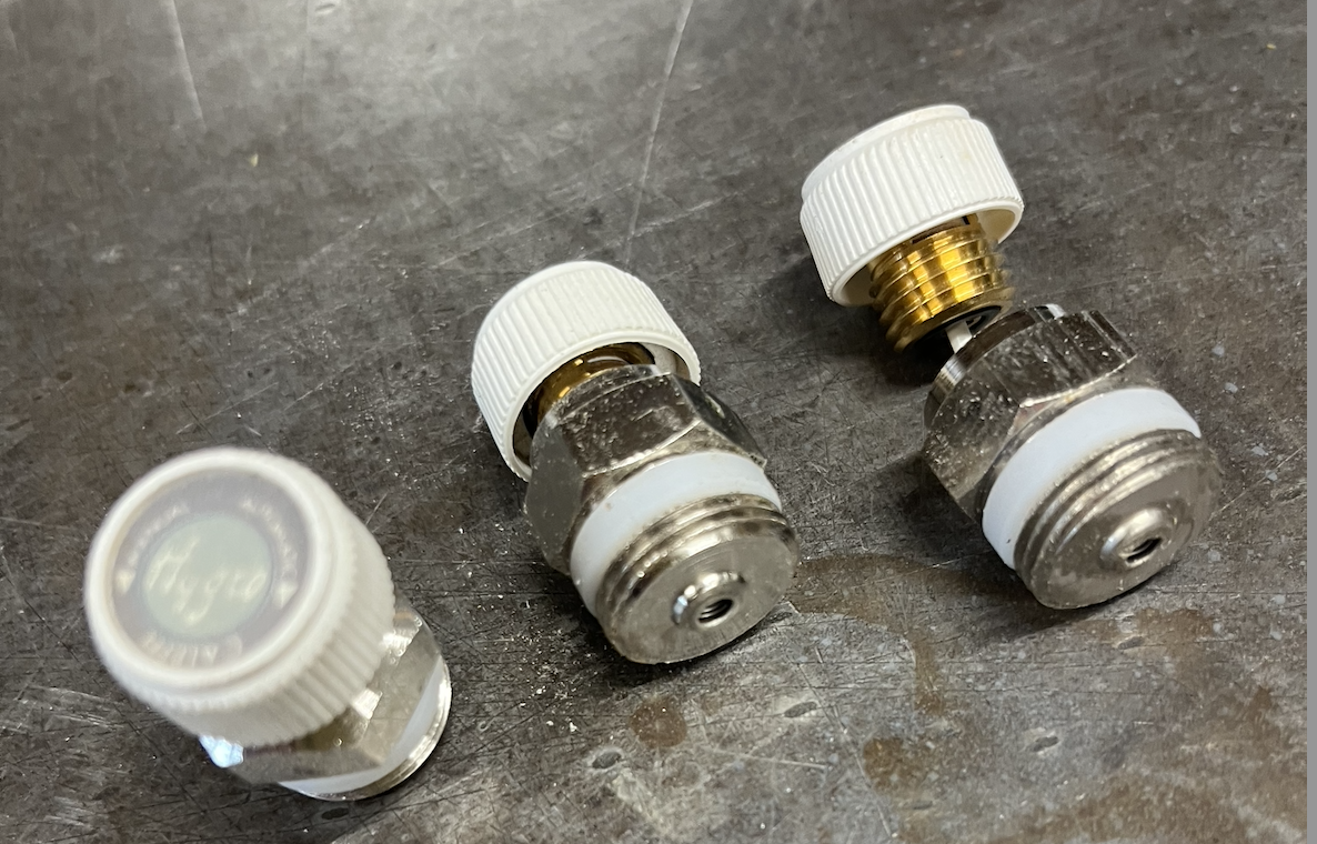
Really should not need a float type vent, the radiator itself will collect the air bubble. Manually vent it out a few times.
I suspect many radiators operate with some trapped air in the top of the sections? It becomes an additional PONPC or expansion volume:)
Nice piping, should have used yellow teflon tape for the look of "heat"!
Bob "hot rod" Rohr
trainer for Caleffi NA
Living the hydronic dream0 -
@hot_rod those air vents are gorgeous lol. Especially if they come chrome plated. My main concern here was future serviceability. I also doubt that the auto air vent is necessary and looking back probably shouldn’t have been put. I was considering using the side outlet maid o mist vents also and putting a caleffi inline check on it. But I didn’t know if they were compatible or not. Best option would’ve just been the coin valves you sent a picture off. Thank you for the offer to send me some valves! Most radiators probably do function with some trapped air lol. Especially the older style rads I see. Where the peak of them is no where near the tapping for an air valve. Here in New York while it’s not common I have seen radiators intended for steam sometimes used on water systems and they work lol. No doubt the top is an unintentional expansion tank.
0 -
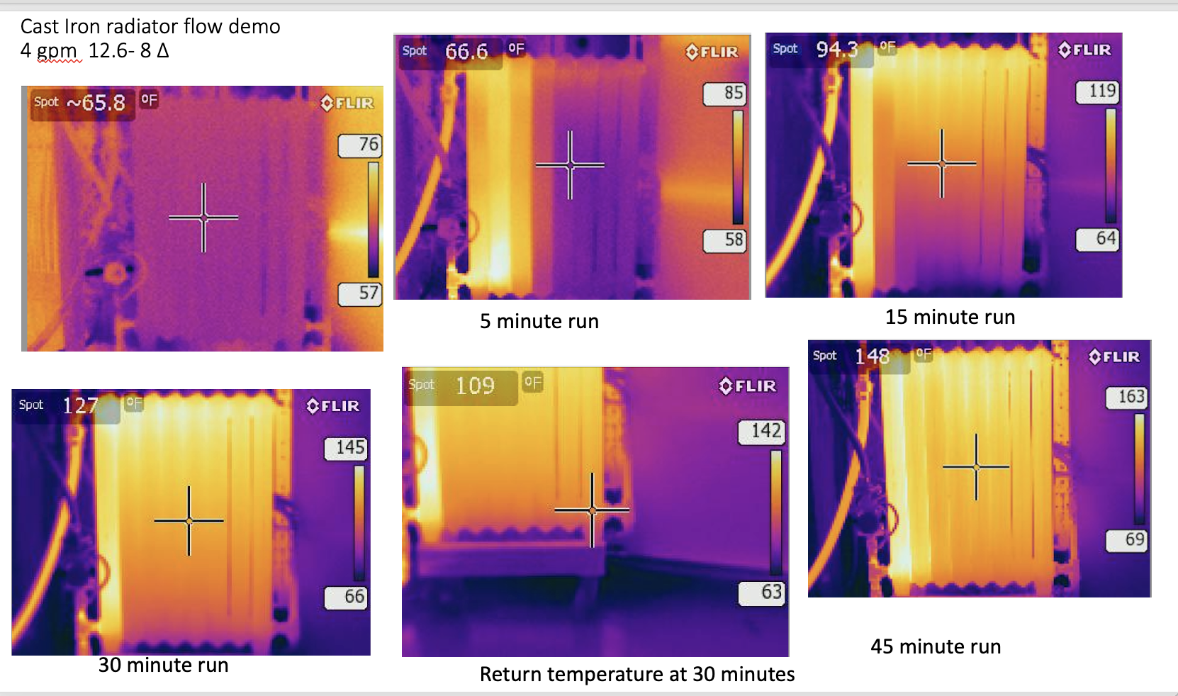
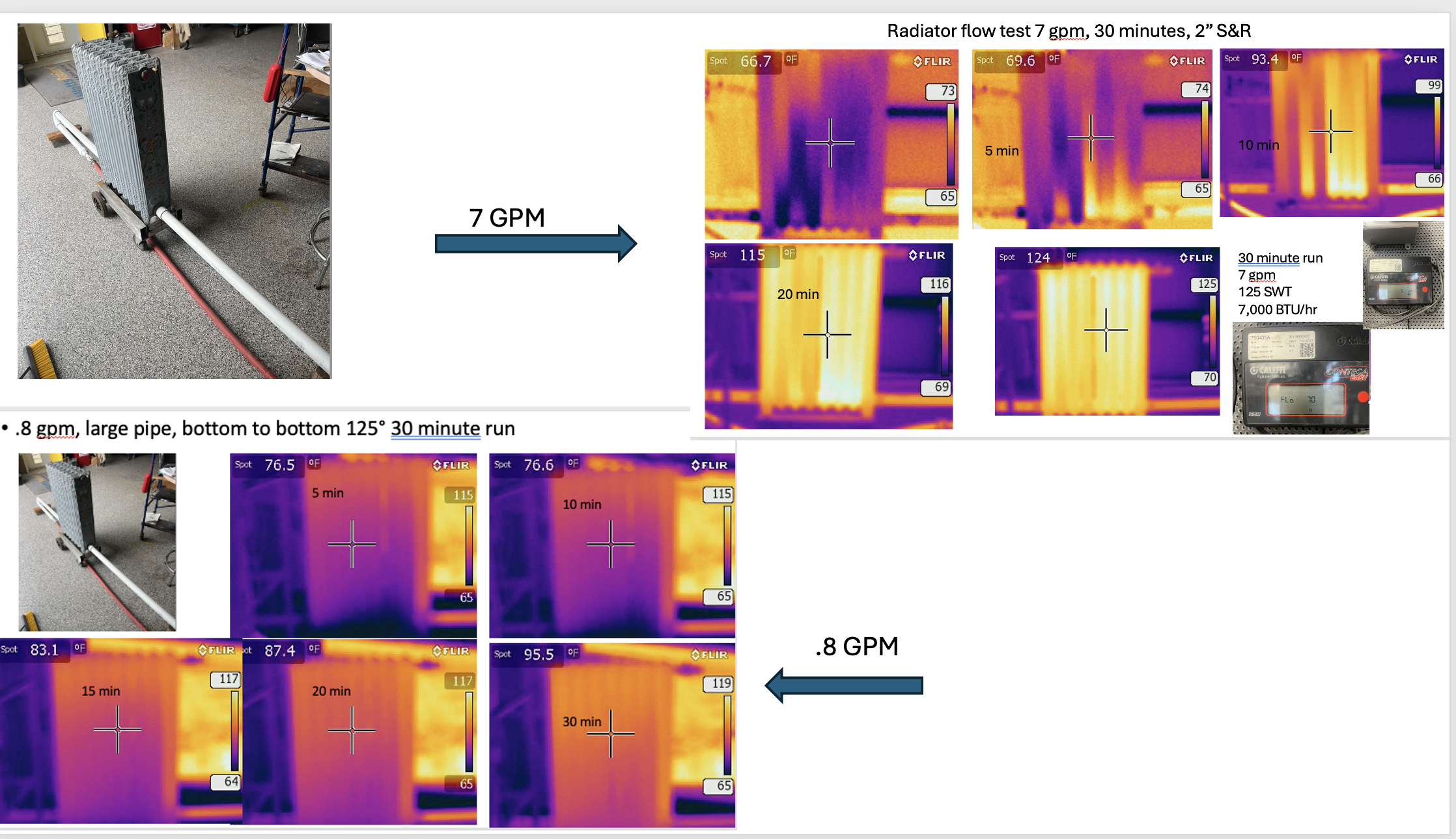
I have flow tested 4 different radiatiors now with various connections, bottom bottom, bottom top cross, bottom top on the same side. Also under flow conditons from 1/2 gpm to 8 gpm.
I have not found any piping combination that doesn't work. And in each test increasing flow rate does allow the radiator to warm faster.
They also heat nicely at 120SWT, when tied into a radiant temperature piping as mine were.
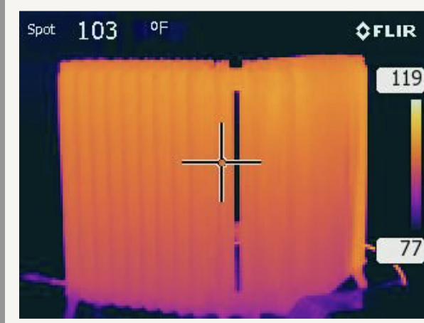
Supply and return on same side
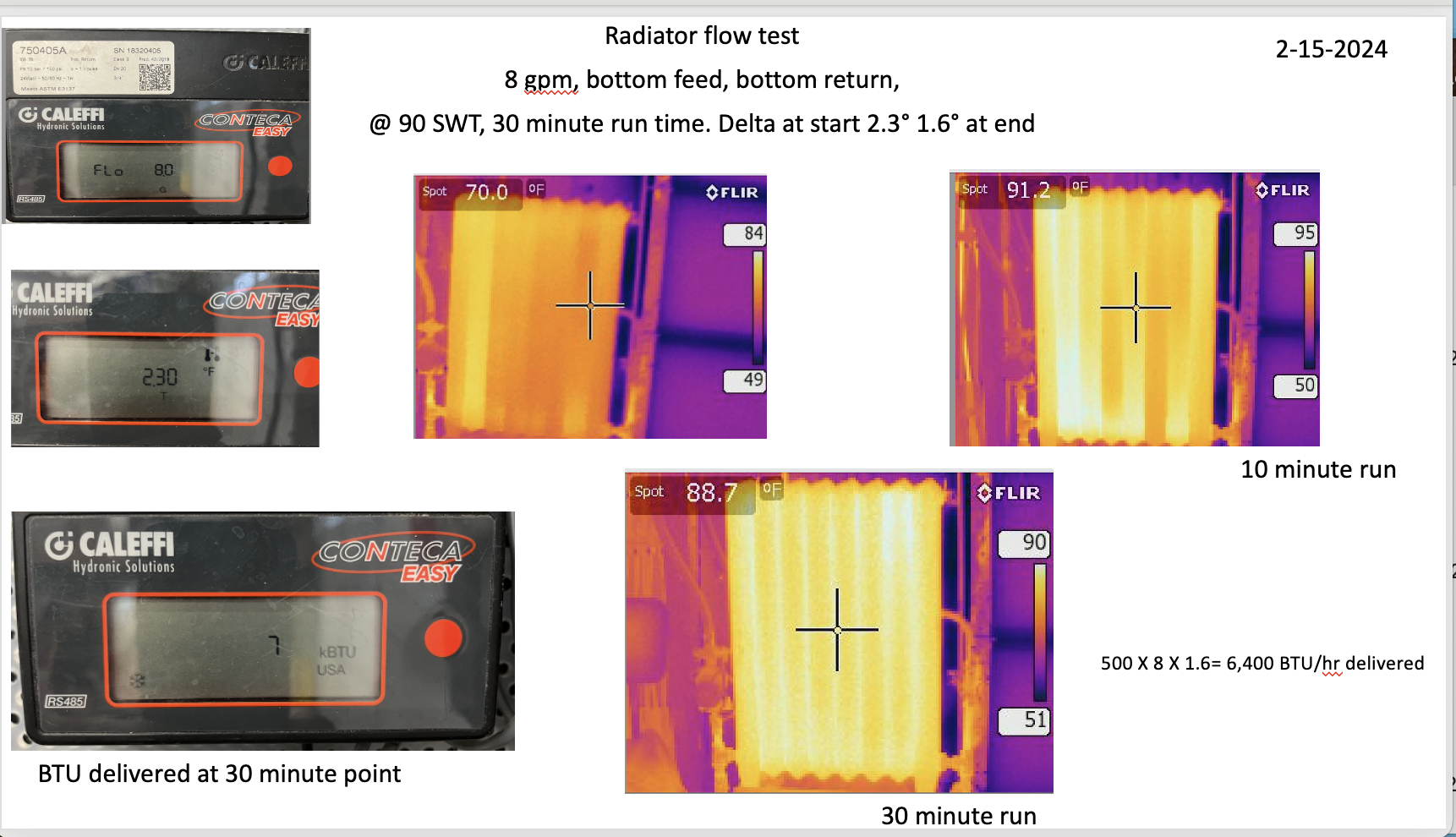
Bottom to bottom at 8 gpm flow
 Bob "hot rod" Rohr
trainer for Caleffi NA
Living the hydronic dream1 -
That’s pretty awesome to see. The supply and return on the same side doesn’t heat the radiator as evenly as bottom left and right. It’s what you’d imagine would happen. The waters easiest path is straight down the first two sections. That’s why I wanted to do it across to force the water into every section evenly. But realistically the room should heat at a pretty similar rate regardless of the piping setup. It’s just so cool seeing it confirmed with a thermal camera. I have one in my truck. Next time I’m at the job if at all I’ll try to get some photos for you.
0 -
I suppose you could run 180- 200°F without issues.
With Steamhead's suggestion I piped a section of 2" pipe in and out.
All the various tests I have done show the increased flow speeds up the radiator heat up time.
This shows a .8 gpm vs the 7 gpm 125 SWT. That is about all I could flow with 1" hose and the Alpha pump I had connected. \
Yes the .8 gpm flow test the radiator got consistently hot after a few hours, similar to what the 7 gpm test showed after 30 minutes.
At some point regardless of the piping connections or the flow rate the mass of iron gets up close to the SWT temperature as the camera shows. I let these cool to 65° for all the testing, but not much load during the fall test days in side the shop.
So my opinion after numerous tests is the higher the flow rater the faster the iron warms. I could never introduce a condition where flow just raced across bottom to bottom without leaving any "heat off the train", so to speak, as the 7 gpm test clearly shows.
This is a large corner radiator in my last shop, 1/2" pex, TRV, probably around .5 gpm@ 110- 115° SWT
 Bob "hot rod" Rohr
trainer for Caleffi NA
Living the hydronic dream0 -
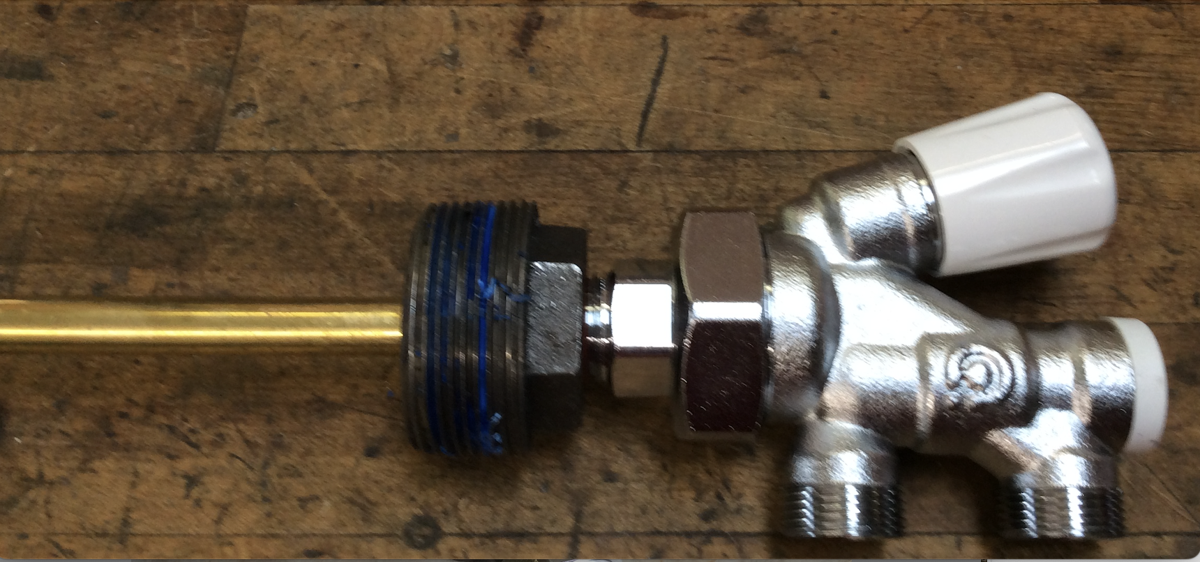
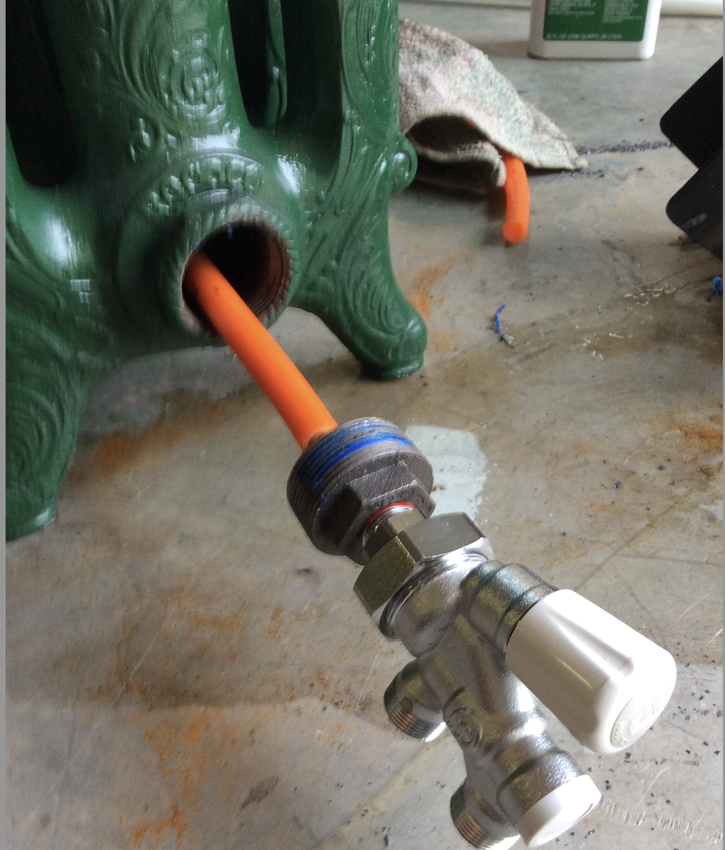
I also tested one of the Caleffi conversion valves, S&R at the same end. I even extended the dip tube with a piece of pex to the far end. But in all honesty it didn't perform any better than just flowing across the bottom.
It simplifies piping, has a balance valve, and has a TRV connection ready to go.
 Bob "hot rod" Rohr
trainer for Caleffi NA
Living the hydronic dream0 -
I've used these valve a number of times for conversions and have always had good success. I used Oventrop but I don't think they're made or available anymore? I didn't know Caleffi made them. I'' keep that in mind.
Miss Hall's School service mechanic, greenhouse manager, teacher, dog walker and designated driver
0 -
I've looked at the radiator installation photos several times and keep asking myself why there couldn't be a tee at the upper right with the vent there instead of having the vent on the left? It would still be at the high point in the system. That would get it out of harm's way. (This is the common sense thought of a homeowner, not someone in the trade.)
0 -
the valve with the lance is more for situations where yo have supply and return pipes on one end and don't have room to move the return to the other end. i think you could make it with some various sizes of copper tube and threaded adapters and reducers if you grind the stop out of the fitting.
0


Categories
- All Categories
- 87.6K THE MAIN WALL
- 3.3K A-C, Heat Pumps & Refrigeration
- 59 Biomass
- 429 Carbon Monoxide Awareness
- 124 Chimneys & Flues
- 2.2K Domestic Hot Water
- 5.9K Gas Heating
- 119 Geothermal
- 168 Indoor-Air Quality
- 3.8K Oil Heating
- 78 Pipe Deterioration
- 1K Plumbing
- 6.6K Radiant Heating
- 394 Solar
- 16K Strictly Steam
- 3.5K Thermostats and Controls
- 56 Water Quality
- 51 Industry Classes
- 50 Job Opportunities
- 18 Recall Announcements