Argo AR826 schematic?

I have an Argo AR826 priority controller. The problem I have is that the main heat circulator only turns off when the priority switches. Seems like it should only come on when demanded. I have searched all over for an owners manual, schematic or pin out. Website does not really give much. Company did not have a manual available. Seems like this is some very rare controller. Anybody have any idea how these work or have the manual?
Comments
-
Do you see any manufacturers date on the control? How old is the system.
That number doesn’t show up even in the retired products. Maybe it was an OEM control that Argo built
Some controls have dip switches to change the relay enable logic, attach a pic.
Bob "hot rod" Rohr
trainer for Caleffi NA
Living the hydronic dream1 -
Can you take and post some pictures of the unit with the cover off and other control equipment ?
Is there a wiring diagram on the back side of the cover ?
National - U.S. Gas Boiler 45+ Years Old
Steam 300 SQ. FT. - EDR 347
One Pipe System0 -
I believe that control has cube relays. The contacts for the main heat are stuck closed. It turns off when priority has a demand because priority removes 120 volts to the contacts for the heat relay.
You could test it by swapping the priority and heat relays and see if the priority zone circulator run constantly.
The cube relays are available.
1 -
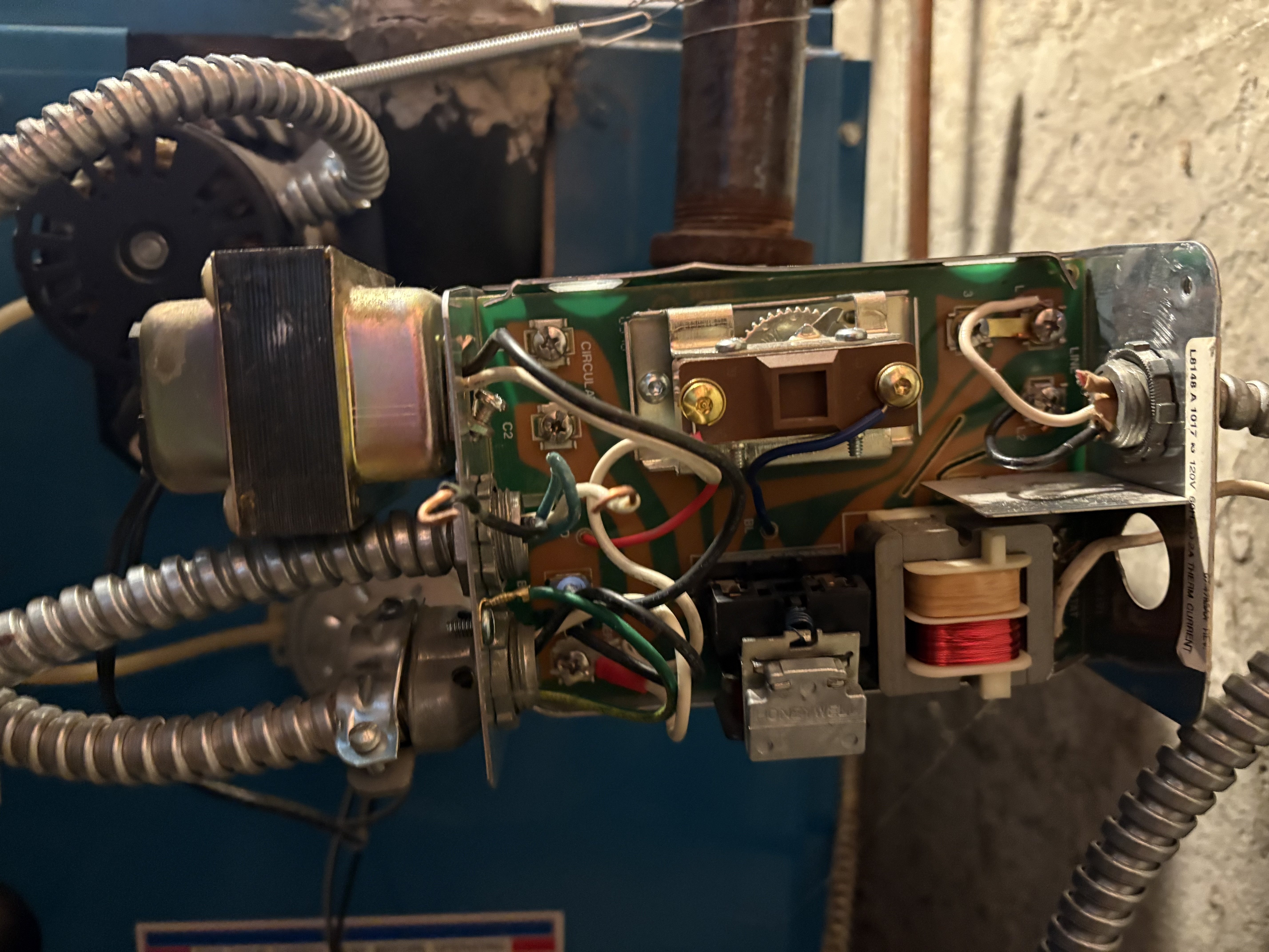
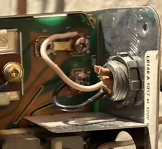
Here is the controller in question. Will need to take pictures of overall set up tonight. It is a mess. No schematics on covers. Problems has been around since we moved in 10 years ago. House built in 83. Problem is in summer, there is heat pumping into the air handler and that offsets AC. Tired of working around this and would like to fix it.
0 -
Do you have an indirect HW tank or tankless coil? The boiler would not be hot in the summer unless it makes hot water also.
You could also have ghost flow from a hot boiler to a zone, if the boiler is maintained hot.
I believe those relays are plug in type, pull one out to see if it stops the pump. Look inside, sometimes you can see the points and determine if they are stuck shut.
Bob "hot rod" Rohr
trainer for Caleffi NA
Living the hydronic dream0 -
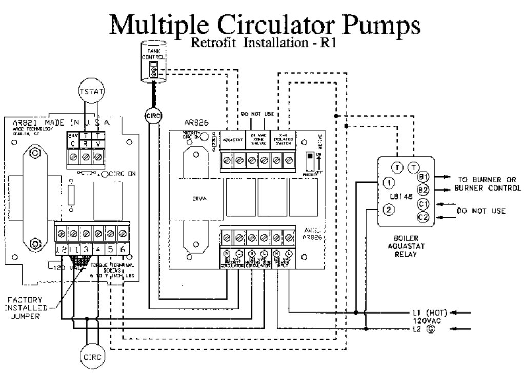
This may help ?
Looks like it is in Priority when the picture was taken. I assume the switch is up for priority.
Your actual issue may be elsewhere. That box may only just provide Priority for the DHW (Domestic Hot Water) circulator. When there is 'No Priority' it may simply provide power for the heat zone circulator which may be controlled by another device. That box (the AR826) does not appear to provide 'Thermostatic Control' for the heat zone circulator. It other words it only interrupts the power for the heat zone circulator to favor DHW circulator.
There is multiple pairs of wires connected to the X-X terminals which leads me to believe there is other control equipment.
You can inspect the relays (the contacts) if they are in sockets and if they are the same part number you can rearrange then to see if the symptoms change. Mark their original location.
The "24 VAC Zone Valve" terminals has me confused as to their purpose (and not used in your case).
Is it just a 24 VAC supply for a thermostat / zone valve circuit.
A control input from a zone valve end switch.
Or a means to interrupt a zone valve control circuit to prioritize the water flow for the DHW.
National - U.S. Gas Boiler 45+ Years Old
Steam 300 SQ. FT. - EDR 347
One Pipe System 1
1 -
I looked online and couldn't find anything on that relay.
I suspect it was to be used with zone valve where the t stat wires go to the valve and the end switch wire would go to "isolated end switch" Don't know if that is how it is hooked up.
1 -
Yes a thermostat or a Zone Valve end switch could be in parallel with the X-X Isolated Switch to control the boiler, however that just lets the Heat Zone circulator run forever, except for the DHW call.
I would think the the "Aquastat" and the "24 VAC Zone Valve" terminals would be contact closure required inputs, energizing the appropriate relay to energize the appropriate circulator. With either 'input' activated it would close the X-X Isolated Switch to control the boiler.
However in this case the "24 VAC Zone Valve" terminals are not used so that theory may be incorrect since the Heat Zone circulator is apparently energized 100% of the time. Unless of course the intent of this AR826 is just to provide DHW priority and not actual zone heat control and the Heat Zone circulator should be switched by some other thermostaticly controlled device.
Like to reverse engineer this box, its pretty simple, probably never have the opportunity.
More pictures of the whole system may help.
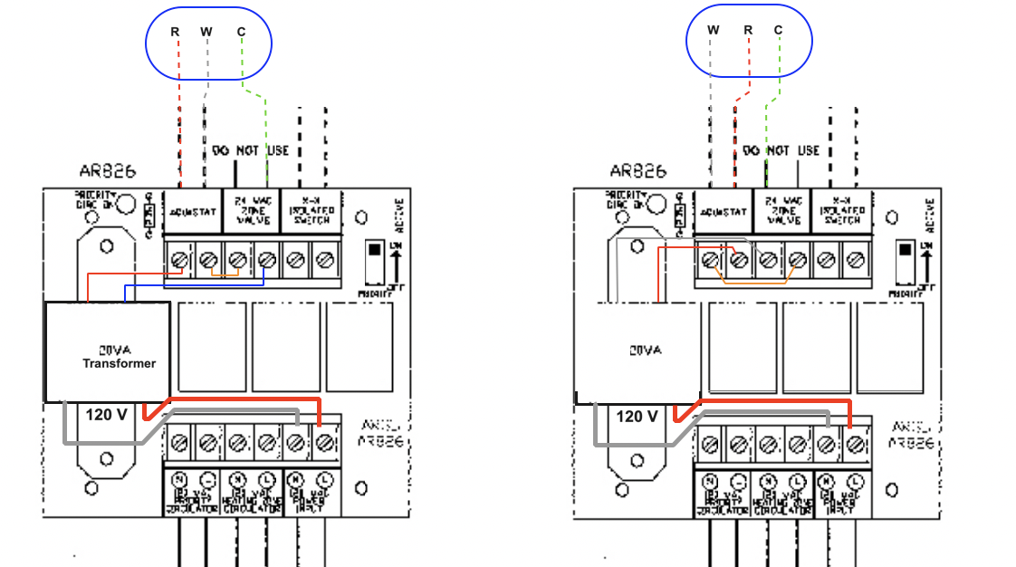
Found this in the other thread posted above. Interesting the image states DO NOT USE for the "24 VAC Zone Valve" terminals.
 National - U.S. Gas Boiler 45+ Years Old
Steam 300 SQ. FT. - EDR 347
One Pipe System1 -
Boiler is used for heat and hot water. Relays appear to work and not stuck. The relays switch when priority is called for.
0 -
I had looked at that thread. Your questions are similar to mine. Confusing. Surprised the spec sheet or owners manual hasn’t made it to Google in this day and age, lol. I will post pics of the other controllers, you will see the mess I’m dealing with.
0 -
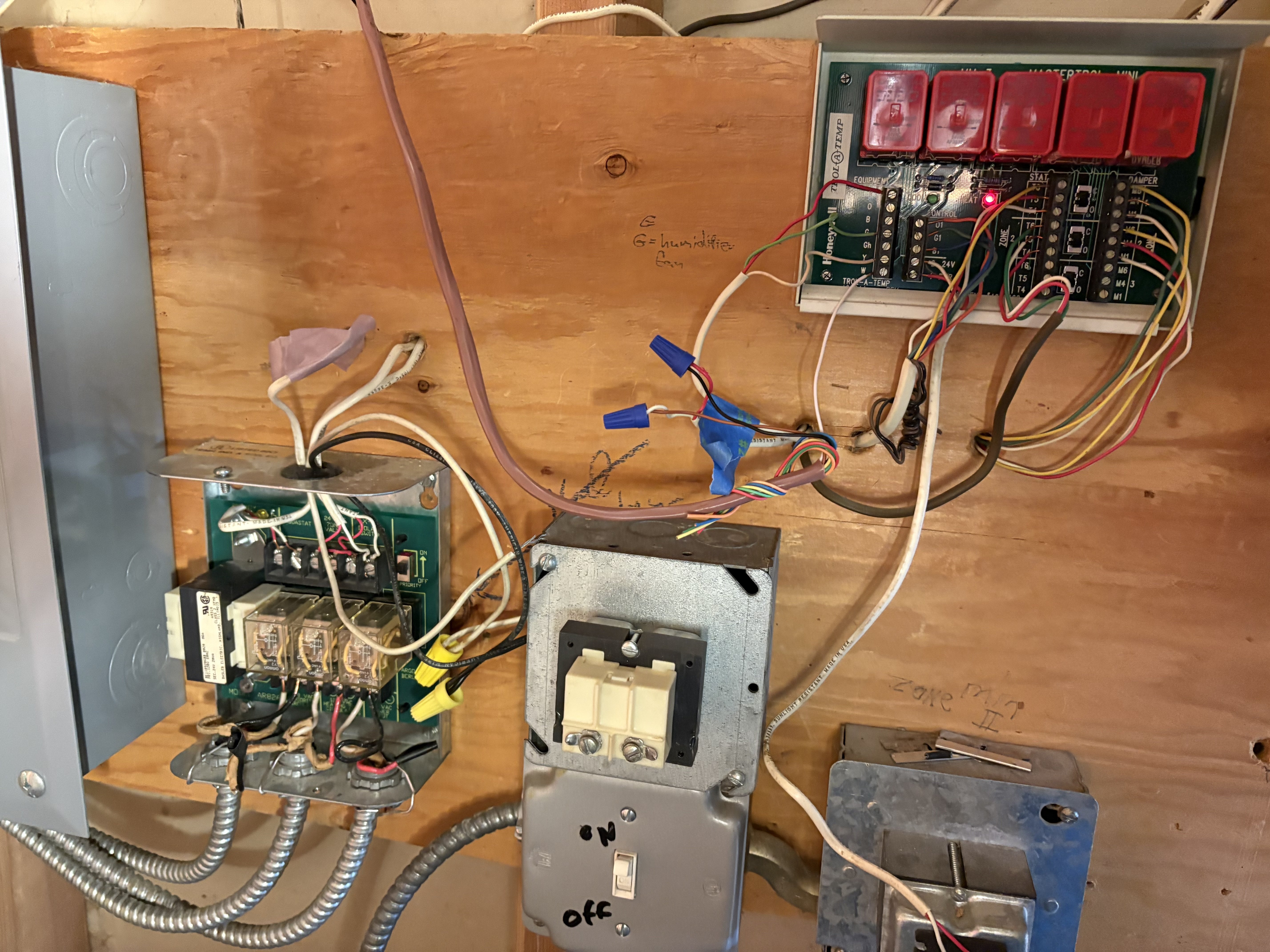
So, have two circulators off the boiler, I would like both off when no demand. Picture 1 is boiler control. Picture to shows the previously mentioned Argo AR826 and the main zone controller. I’m starting to think…as suggested above, that the 826 was intended to work with another Argo controller. I did find a document in the Argo historical files that shows some interconnects, but not the combination I have. May have to add another relay to the wall to get it to switch off…. Will get back on it this weekend..
Oh…and thanks for all of the notes and help above. Nice to see a forum where people jump in to help!
0 -
what is the Honeywell Trol temp being used for? That was typically for zoning hvac dampers
Bob "hot rod" Rohr
trainer for Caleffi NA
Living the hydronic dream0 -
There are two air zoning valves for upstairs and downstairs.
0 -
This may have some clues in it.
0 -
May be time to replace the relay with a newer model that has the functions you want? Caleffi has great relay boxes👍🏻
I’m looking for a date on that Argo? Its possible that transformer was built 19th week of 1993 based on one number printed on it?Bob "hot rod" Rohr
trainer for Caleffi NA
Living the hydronic dream1 -
Well I can't see how the BX cables and the low voltage wiring interconnect between things. So I can't tell what controls what.
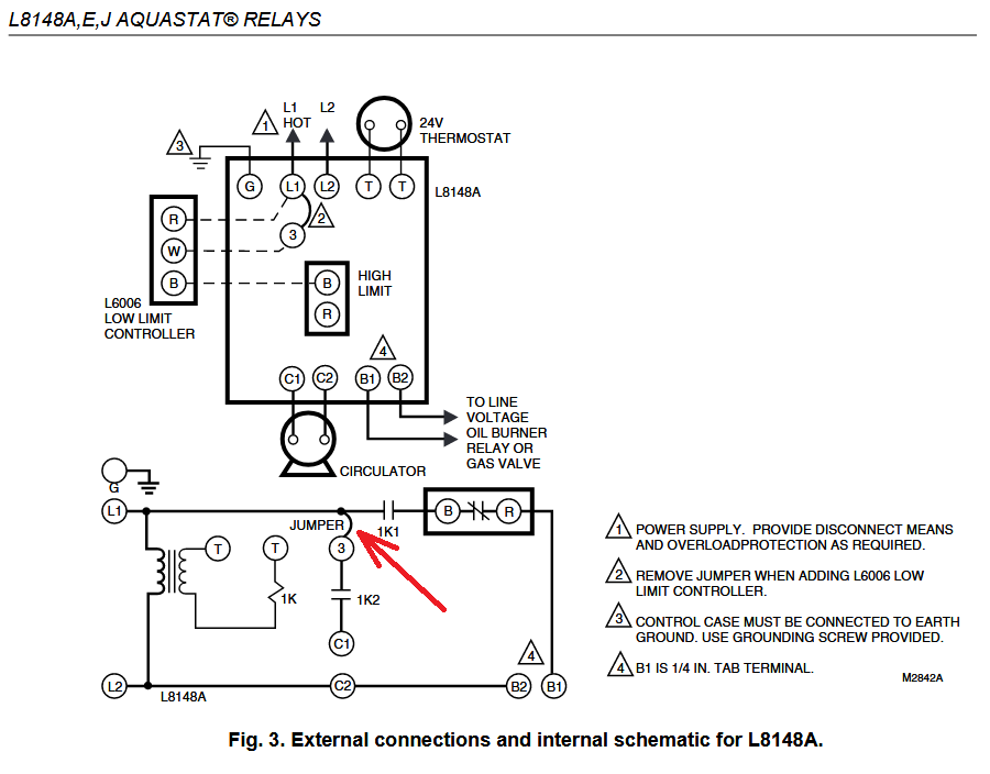
I'd say this is the intent from Argo but there is too many wires in your L8148A for it to be this way.
 National - U.S. Gas Boiler 45+ Years Old
Steam 300 SQ. FT. - EDR 347
One Pipe System0 -
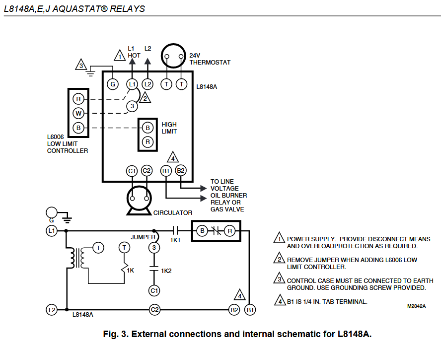
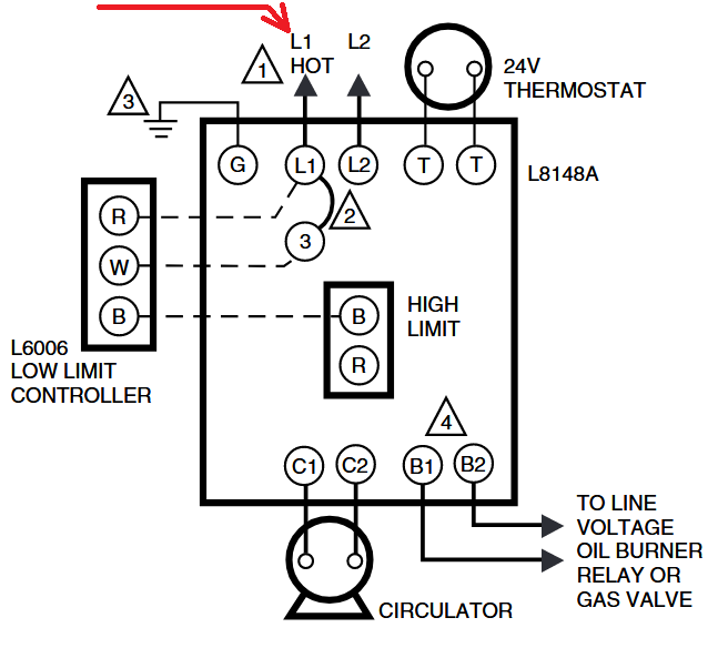
I'm thinking the L8148A Aquastat should have the ultimate On-Off circulator control. The AR826 just steers which circulator is used and is the DHW call for heat to the T-T of the L8148A Aquastat.
During no call for heat the L8148A Aquastat should shut down all power to the circulator(s). However that may disable the DHW independent autonomous priority.
I fear the way they have it wired, you have a 'Which is first the Chicken or the Egg' circulator power situation. since if the L8148A Aquastat kills the power to the AR826 you loose the ability to have an independent DHW call. Not good.
National - U.S. Gas Boiler 45+ Years Old
Steam 300 SQ. FT. - EDR 347
One Pipe System1 -
This is all actually very helpful. The schematic for L8148A gave me an idea…. I’ll have to think on it, but will certainly share if I ever sort this out. The right answer would be a new control system, but I hate to be beaten by this now….
0 -
With the control equipment you have pictured I don't see how this can work correctly.
I'm assuming this is a chronic situation and not a new defect ?
I'll think about it a bit.
Boiler make and model ?
National - U.S. Gas Boiler 45+ Years Old
Steam 300 SQ. FT. - EDR 347
One Pipe System0 -
Looking closer at your L8148A Aquastat C1 and C2 are not connected to anything.
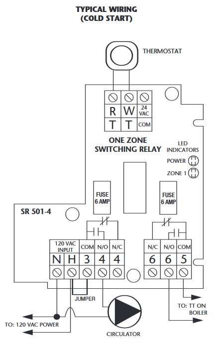
The easy fix is this diagram using a AR821. However the AR821 may not be available, a Taco SR501-4 may be a good substitute (there may be others). There are more expensive options that would replace the AR826 and the AR821 combination. However I like socketed (easily to replace) relays so I'd be inclined to keep the AR826 and add an appropriate switching relay to control the Heating Zone circulator.

 National - U.S. Gas Boiler 45+ Years Old
Steam 300 SQ. FT. - EDR 347
One Pipe System0 -
The way to do this is to get spec sheets on the controls you have. Then look at all the wires and figure out what is what
Figure out how it should work , what you want it to do and sit down and draw it out. After you scrap you first two drawings you will get it.
Trying to figure out what someone else did muddles your brain. Start from scratch and you will get it, pretend it is a new job instead of trying to figure out a mess.
0 -
" The way to do this is to get spec sheets on the controls you have. " ???
They don't appear to exist.
I think the wiring diagram that @roberttakacs found pretty much explains it. That the AR826 is a one zone for DHW priority only not a two zone with one zone as DHW priority.
Personally I like reverse engineering (if you can), since you will probably learn more (I do). Also since if you have a good idea how the system should work, all you have to do is figure out if it is a recent defect or an original design issue. In this case it looks like it is an original design issue. (which is sad, since running a circulator almost continuously (if it is not actually needed) for presumably decades, in a system that has an integrated DHW is a huge waste of energy IMO, it is probably heating things that don't need heating, and maybe increasing the A/C load too).
Additionally whose dime are you on ? With a contractor it may be faster and overall less expensive to rip out the unknowns and install a modern replacement. In this case (assuming it is a home owner) his labor may be free to him and learning the deficiencies of the design and resolving it with an inexpensive switching relay may be the most cost effective way.
Also he benefits by learning the system in case there is future problems.
In this case I would also identify the cabling at each end and neaten things up a bit.
National - U.S. Gas Boiler 45+ Years Old
Steam 300 SQ. FT. - EDR 347
One Pipe System1 -
Thanks guys. The problem has been there since we bought the house. Would unhook heat circulator in the summer, but got sick of that. I had the air handler and AC replaced this summer and suggested to my guy we should do boiler and controls. He talked me out of it. Of course, I assumed these things would get sorted out…. Anyway, I decided it needed fixing.
0 -
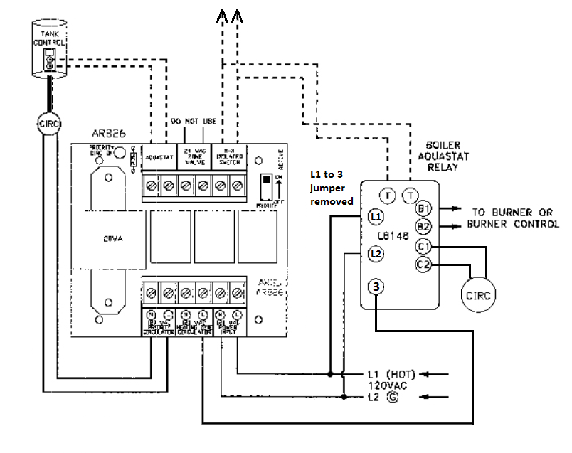
Now for the good news. Thanks to the assist here, I got it working. The solution was remove jumper between L1 and 3 on the L8148a. I then ran the circulator output for the heat from the AR826 to term 3 on the 1K2 relay on the L8148a relay. Then ran C1 and C2 to the circulator. Seems like problem resolved. Both circulators off with no demand, and appropriate circulator appears to be working as demanded. Just need to clean things up now and add in the humidifier that was disabled when they put in the air handler. :-(. Thanks again for all of the help!
0 -
With the Jumper L1 to 3 removed what powers the Heat Zone circulator ??? With the jumper removed there is no L1 to C1 connection via relay contacts 1K2. C1 should never be energized. Also see note 2, Jumper removal, it for a external controller.
 National - U.S. Gas Boiler 45+ Years Old
Steam 300 SQ. FT. - EDR 347
One Pipe System0 -
power now comes into the relay from the 826, through the relay and to the circulator. I can try to mark up my schematics tomorrow to post it.
0 -
So I believe this is what you did ? Not perfect… OOPS, I looked it over closer.
Maybe it is perfect!!! I like it, I think it will work good. I'm surprised the original Argo documentation did not use that method. Very nice, I'm disappointed I did not think of it. Everyone learned something.
 National - U.S. Gas Boiler 45+ Years Old
Steam 300 SQ. FT. - EDR 347
One Pipe System0 -
I just noticed this. Typically L1 is the Hot wire (Black) and L2 is the Neutral (White).
 National - U.S. Gas Boiler 45+ Years Old
Steam 300 SQ. FT. - EDR 347
One Pipe System0 -
Hello, good eye. I did swap hot and cold wire before rewiring. Yes, that what you show is effectively what I did! Your diagrams gave me that lightbulb moment!
0


Categories
- All Categories
- 87.5K THE MAIN WALL
- 3.3K A-C, Heat Pumps & Refrigeration
- 59 Biomass
- 429 Carbon Monoxide Awareness
- 124 Chimneys & Flues
- 2.2K Domestic Hot Water
- 5.9K Gas Heating
- 118 Geothermal
- 168 Indoor-Air Quality
- 3.8K Oil Heating
- 78 Pipe Deterioration
- 1K Plumbing
- 6.6K Radiant Heating
- 394 Solar
- 15.9K Strictly Steam
- 3.5K Thermostats and Controls
- 56 Water Quality
- 50 Industry Classes
- 50 Job Opportunities
- 18 Recall Announcements