Tee too close to elbow?

First of all greetings everybody. I’m in my second year as building engineer at my old high school and need expert opinions. I understand that there should be a decent run of straight pipe upstream of a circulator because a 90(edited) can cause turbulence. (I’ve seen this phenomenon firsthand with forced air. The new register won’t blow because the starting collar is immediately after an elbow.)
There’s an issue with a pair of boilers that serve the athletics areas, including air handlers, and heat Exchangers. Water to and from the building that I’m calling primary looks mostly correct. Return water enters the boiler room past the thermometer that’s usually showing about 110°-120°. Water flows past a T that goes to the pair of boilers and then past another T from the pair of boilers then through the air separator and circulator, and then back out to the building. Boilers operate in stages with the more efficient boiler as stage one. Target is 160. I would expect boiler one to settle into some equilibrium firing rate most of the time but instead it’s always going from its minimum to 100% and it shuts off quite a bit. Second stage boiler comes on for two or three minutes at a time. The other odd thing is that the return water to from the boilers is constantly moving between 120 and 160.
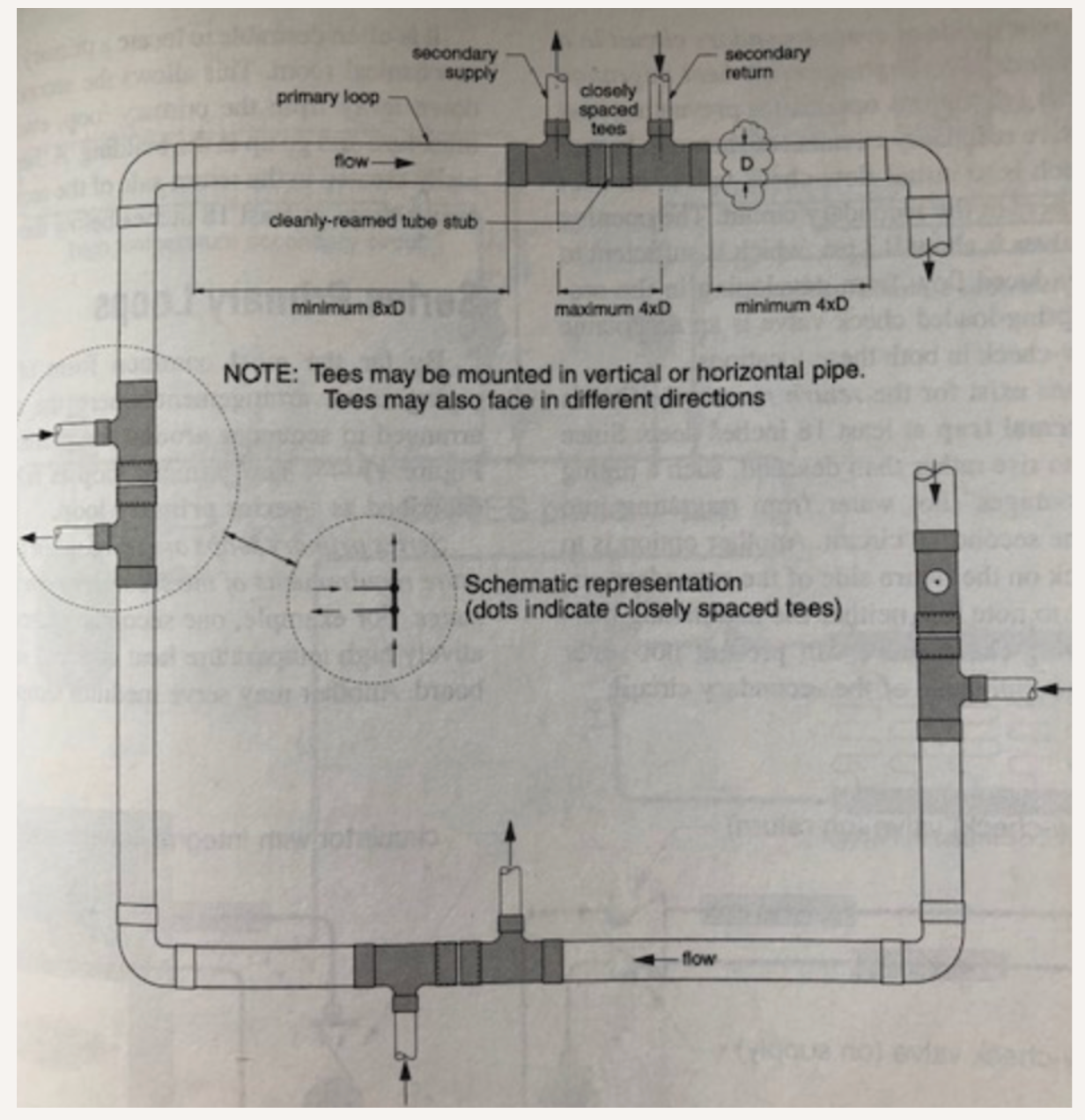
Here’s what I think is going wrong. The T sending water to the boilers is immediately after a 90° elbow. The T returning water from the boilers is immediately after the first T. “Closely spaced T’s” are not helpful here. Turbulence immediately downstream of the 90 is causing unexpected pressures where water is supposed to turn into the T. To make matters worse, modulating valves make the rate of flow to and from the building fluctuate so the turbulence keeps changing.
I’ve concluded that water from the boilers is making an unexpected unintentional U-turn back to the boilers because of turbulence from being too close downstream of the 90.
Thoughts?
try pressing the red button
Comments
-
btw each boiler has a circulator.
try pressing the red button
0 -
If you want equilibrium I would think you would want to slow down some of the the system's agility, so it can't make quick changes. Slow down the advancement of the firing rate.
National - U.S. Gas Boiler 45+ Years Old
Steam 300 SQ. FT. - EDR 347
One Pipe System1 -
how are the boilers controlled? it sounds like a control problem in that the boiler is trying to fireat its maximum rate to maje a certain delta t but there isn't enough load to absorb that much energy so it immediately hits high limit and shuts off. what you really want is to start at a low to moderate firing rate and slowly increase the firing rate if the swt temp setpoint isn't reached. better residential mod con boilers have settings to control this type of behavior. i don't know about commercial boilers.
0 -
You have a primary/secondary system with closely spaced tees. I suspect if the water temps are not stable you could have a flow issue.
Lets call your heating loop the secondary and the boiler loop the primary.
I would like to see some pictures of the piping.
Usually, the secondary loop flow exceeds the primary loo flow. But in your case maybe not. If the boiler primary loop flow exceeds the secondary loop flow water will flow backwards in the secondary loop between the two spaced tees and screw thing up.
You can easily check this by measuring water temps:
Return from building temp
supply to building temp
return to boilers temp
and supply from boilers temp.
Do this with either 1 or two boilers on but during the whole test you have to keep things the same either 1 boiler or two boilers on and firing rates locked.
Do both boiler pumps run all the time or do the boiler pumps start and stop with the boiler?
0 -
To answer some questions
Boiler one tries to maintain supply 160 and I’ll find out under what conditions boiler two fires. Observing boiler one, I don’t know what calculations determine firing rate but I’m not thinking that it should ramp up slower or ramp down faster than it does. Watching the return temperature climbing at the boiler makes me suspect piping problem. Boiler one circulator runs continuously Boiler two circulator runs intermittently. System circulators take turns but only run one at a time. Each circulator is three phase and the speed is determined by the setting of their “freq drive”. System circulator is usually close to 39%. Boiler circulators run at 50%. Boiler circulators are hanging from the ceiling in line with the pipes, but the system circulators are big floor mounted beasts.
Although, now that you make me think of it, there is quite a bit of distance to and from the loads which are modulating valves, so the GPM through the system, even with a giant pump, might not necessarily exceed the GPM through the boilers.
thanks for the insight. Stay tuned.try pressing the red button
0 -
If the boilers fire and you see the return temp jump up that is a classic sign that the water is "backing up across the bridge"
A lot of engineers don't understand how the flow rates in the two loops interact with one another.
If the water is backing up its because the secondary loop is probably not flowing enough. Would have to know more about the system to help.
Several of @DanHolohan describe this. Probably "primary/secondary pumping made easy" is the book you need.
Whatever you need to do with the controls and the pump speeds is the fix. Running the way you are will short cycle the boiler as well.
I had a chilled water system years ago where the chiller never ran right and constantly tripped on oil failure as it seemed to never have a load and short cycled. It was also primary secondary. getting the flow rates right fixed it after 10 years of not running right.
0 -
Ideally you want pipe dimensions along this line.
Too close would not cause the symptom you describe.
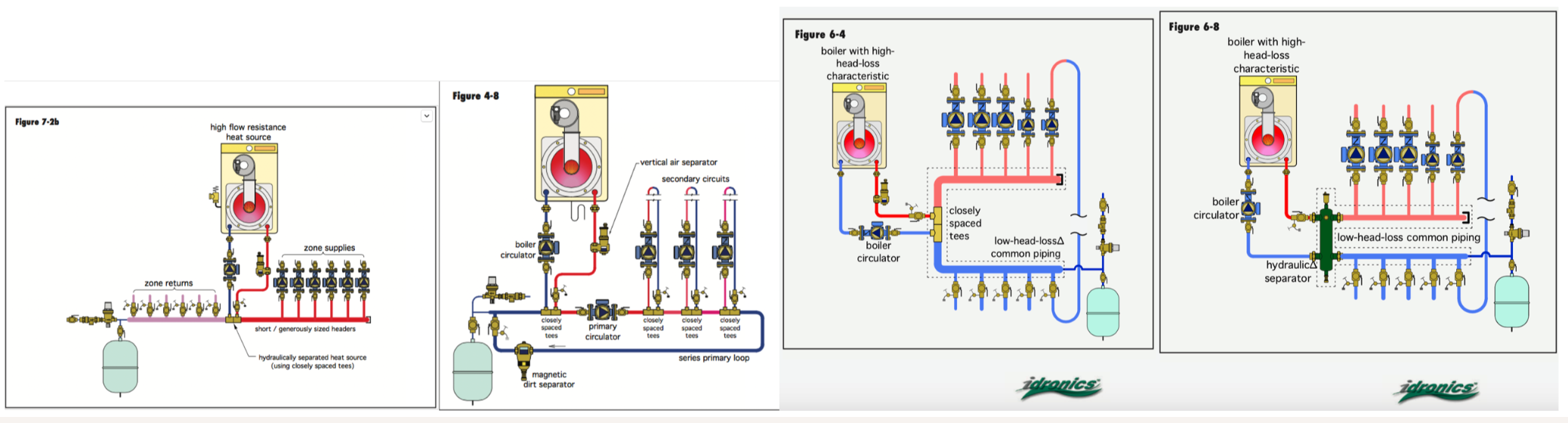
I wonder about pipe sizing? The primary loop, the loop the boilers inject into, needs to be sized to handle GPM if both boiler pumps are running.
Is there a dedicated loop with a pump, like this, fig 4-8?
A sketch may be a better view.
 Bob "hot rod" Rohr
trainer for Caleffi NA
Living the hydronic dream0 -
Does the system loop have a way to produce flow if no zones are calling or is it basically a pipe between a supply manifold and a return manifold with the boilers tapped in to it so if few zones are calling there will be little circulation?
0 -
If the GPM to and from the building exceeds the GPM to and from the boilers, I would expect the return temperature from the building to be close to the return temperature to the boilers.
If the GPM to and from the building is less than the GPM to and from the boilers, I would expect the supply temperature to the building to be close to the supply temperature from the boilers.
Normally, I would expect the first example to be the case. The Supply water out to the building would be a mixture of building return water and boiler supply water and the temperatures would indicate the ratios involved. GPM entering a T equals GPM leaving a T.
Pumping away and primary secondary by Holohan are in my house somewhere so
I would have connected each boiler to the building loop with its own pair of closely spaced tees but I’m not in any position to make those decisions. The boiler room got relocated and totally re-piped this year because of an addition being built. I am in a position to report that “the relief valve is leaking, the system pressure is all over the place and I can’t find the expansion tank. Does the contractor still owe us an expansion tank?” That was a couple weeks before the expansion tank appeared.Did you guys miss the photo that I put into my comment immediately after my original post? It shows the return from the building with tees to and from the pair of boilers.
Just now, I looked back at my photos from last week and I had recorded in that moment the return temperature to the boiler exceeds the supply temperature to the building. My only explanation is GPM exiting the west end of the tee equals GPM entering the side of the tee plus GPM entering the east end of the tee minus GPM leaving the east end of the tee.
Hot Rod true. Pipe sizes would be good to know but that would require a ladder and a sharp knife. And I can only guess as to the relative GPM‘s based on temperatures. Figure 4-8 is not what’s there. Somewhere in my big long original post is a description of the series of components and the circulator then out to the building. The loads are piped parallel, and the ones I’m aware of have modulating valves and can be viewed in the building automation program. Speed of the building circulator always displays near 39% even when the modulating valves are showing 0% open. I’ve asked about and looked for a path for flow when nothing is calling, ideally near the furthest heat exchanger, but haven’t gotten a straight answer. So it’s likely that the building circulator spends plenty of time stuck at the left end of its curve.
BTW the upper left part of the black-and-white image shows a 90 upstream of a T. The section of pipe connecting them has its length indicated as “minimum 8xD”. Again, I can’t help but thinking that crazy stuff is happening in that T caused turbulence from being too close to a 90.
I appreciate all the time and expertise and good advice but I was really hoping that someone here would have firsthand experience of something similar.try pressing the red button
0 -
yes, variable speed pumps will make for variable temperatures both in the boiler loop, and the system loop.
Do the boilers and system have variable speed pumps?
That being said, some variable speed controls are watching a mixed temperature condition and will speed up and down to hold that close, fixed temperature. This has always been the tekmar approach, vary to pump speeds based on a temperature input.
If your pumps are varying speed bases on a ∆P condition, as valves open and close in the system, expect the temperature to vary a bit more.
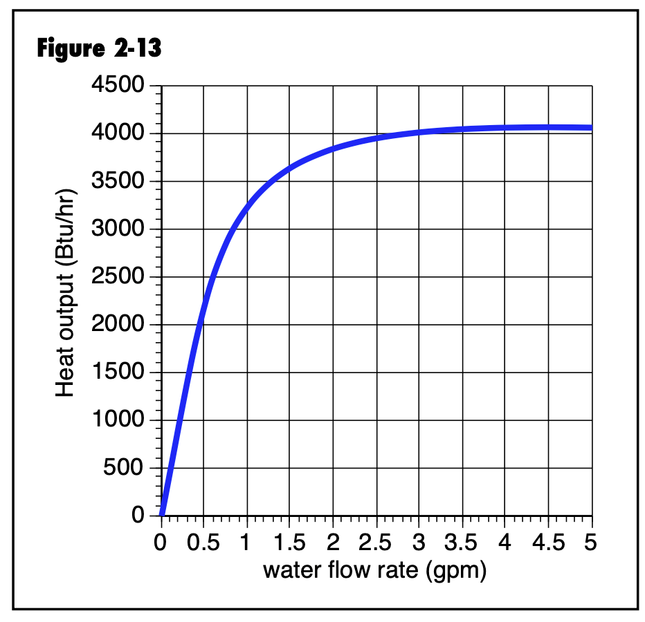
This graph will look the same regardless of the type of heat emitter, obviously these low flow conditions would be a residential system, but even with 50 gpm flows, the curve would look the same. This is the challenge with varying flow to change heat output. Sometimes called a hockey stick curve :)
So it comes down to what the control logic is for your system, temperature or ∆P modulation.
Changing heat output to the system is easier, more stable with temperature modulation as it tracks with loads closely, looking at ODR curves you see that relationship.
In a perfect heating control, we adjust the heat input to exactly match the heat loss at any given point.
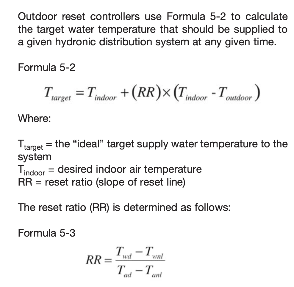
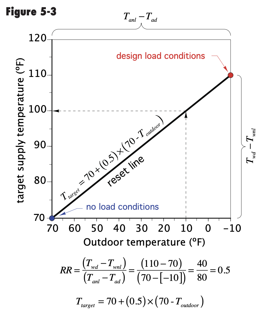
Are the boilers on outdoor reset? Or what brings on a second boiler, a drop in supply temperature to the system? What control is handling that task?
Flow control can cause wide temperature swings and it makes it harder to track a changing load in the building.
In a piping system there are three flow conditions laminar, transitional and turbulent.
To transfer heat out of the fluid stream into any heat emitter you want turbulent conditions. That condition is not something you can or want to design out of the system or you loose heat transfer.
While that close ell/ tee is not picture perfect, I don't think this is that temperature blending problem. Look more into what controls the pump speeds.
Bob "hot rod" Rohr
trainer for Caleffi NA
Living the hydronic dream0 -
Variable speed pumps?
Already answered. Circulator sending water to and from the building is a floor mounted three phase beast and its freq drive constantly displays a number very close to 39%. Each boiler has a three phase pump in line with the piping big enough to have its own support from the ceiling. Freq drive on number one displays 50%. Number two sometimes displays 0%.
Thanks for the hockey stick. Heat transfer varies with flow rate but diminishing returns happen eventually. Graph is good to reinforce the concept.
Outdoor reset?
You’re preaching to the choir but it’s not used here. Boilers are trying to make 160° always. I don’t think there’s a target for the supply water out to the building, just whatever the boilers can do.
What brings on the second boiler?
Building automation enables boiler two if return water is below a certain temperature for a certain amount of time.
Turbulent conditions?
Yes, a component that’s responsible for transferring heat usually has some means of creating turbulence built in, like textures inside the tubing to disrupt laminar flow. Ok, I suppose a Spirovent causes turbulence too. But other than that I’ve never heard of deliberately creating turbulence in near-boiler piping and I’m not sure why you brought that up.
So, Mr Rohr, you don’t think that the tee being immediately after the 90 is causing the problem that I’m describing. That is the answer I was looking for although I was hoping that someone would concur with my conclusion or have dealt with a similar experience. Again, I appreciate the best experts suggesting other things to check, but still, I can’t fathom how the wrong flow rate or the wrong firing rate or the wrong boiler target temperature would ever cause the temperature of the water going to the boilers to exceed the temperature of the water going to the building. I do agree with the installers and with everyone here. I wouldn’t expect water in the boiler loop to go past the water in the building loop in the opposite direction like the arrows I drew on my photo. Yes, that seems farfetched. Still, the distance between the 90 and tee being about zero pipe diameters looks mighty suspicious.
try pressing the red button
0 -
" I can’t fathom how the wrong flow rate or the wrong firing rate or the wrong boiler target temperature would ever cause the temperature of the water going to the boilers to exceed the temperature of the water going to the building. "
I think you said this system was all torn apart and rebuilt in a different location. Did it work correctly before the relocation ?
Have the sensor position, locations, integrity and electrical connections all been verified ? VFD control going to the correct motor drives, phase rotation corect ? If the software does not have good accurate data and / or control, how can it be expected to work correctly ?
If the contractors forgot an expansion tank, getting the electrical correct may be a huge challenge.
National - U.S. Gas Boiler 45+ Years Old
Steam 300 SQ. FT. - EDR 347
One Pipe System0 -
This is what I think your not understanding
"
" I can’t fathom how the wrong flow rate or the wrong firing rate or the wrong boiler target temperature would ever cause the temperature of the water going to the boilers to exceed the temperature of the water going to the building. "
I am not going to try and convince you that if the flow in the boiler loop exceeds the flow in the building loop that the water will flow backwards between the two tees. I could draw it out but it seems your mind is made up. Sounds just like what I posted a week ago. But I could always be wrong.
If the flow rates are right, you will always get building return temp to the boiler returns
If the flow rates are right the boiler outlet temps will be warmer than the building supply when the boilers are on and firing.
Read "Primary secondary pumping made easy"
0 -
Yes, I am convinced that when flow through the boiler exceeds flow through the building then flow through the common piping gets reversed. All of the return water from the building combines with some of the supply water from the boiler and gets sent back to the boiler, right? And the supply water going to the building is 100% water that just came from the boiler and very close to boiler outlet temperature, right? It’s been years since I read the book that you mentioned, but I recall that the piping in common could have flow in one direction OR the other.
I agree that building return temperature can equal boiler return temperature. I agree that boiler supply temperature can exceed building supply temperature. I’m pretty sure I get how it’s supposed to work.try pressing the red button
0 -
For those of you copying and pasting my words and sticking quotes around them please read slowly.
“the water going to the boilers
to exceed the temperature of
the water going to the building”When I find my Pumping Away book I’ll see if I find that scenario without additional piping or mixing valves.
At 109a
Yes, the boiler room used to be in part of the building that got torn down. Yes, system was fine before boilers got relocated. In fact, I think it was set for 150°.
Sensor positions & electrical connections checked? No. Correct motor running? That definitely would have been noticed if wrong. Spinning the right direction? I’d expect obvious problems if wrong but it wouldn’t hurt to make sure. Wrong data causes wrong operation? Agreed.How would you deliberately mispipe or incorrectly operate a system like this to achieve return water to the boiler hotter than supply water to the building?
Slowing water to/from the building would increase the temperature of building supply water. Slowing water through the boiler would increase its temperature rise but that wouldn’t cause the boiler return temperature to increase.
All these different ideas are helping me attack this from various angles. Thank you for that.
try pressing the red button
0 -
“the water going to the boilers
to exceed the temperature of
the water going to the building”Your point ???
I agree that seems impossible, so I tried to list other possible defects (mostly electrical that a contractor could easily mess up) in the relocation and rebuild process that would explain what you are seeing and the system behavior. Which is why I asked if it all worked normally before the equipment move.
Does your system actually verify the flow and flow direction or just simply display what the pump motors are commanded to run at ?
Without verification, just because a screen states the pump's motor drive is set at a certain percentage does not mean it is actually happening. Sadly sensors fail and wiring gets reconnected incorrectly all the time.
National - U.S. Gas Boiler 45+ Years Old
Steam 300 SQ. FT. - EDR 347
One Pipe System0 -
Maybe when they re piped it the two closely spaced tees got reversed. The return from the building should also be the tee that returns to the boilers…..not the supply from the boilers maybe they crossed that up
 1
1 -
Agree. Although I'm hoping for an electrical issue, may be easier to correct during heating season.
National - U.S. Gas Boiler 45+ Years Old
Steam 300 SQ. FT. - EDR 347
One Pipe System0


Categories
- All Categories
- 87.6K THE MAIN WALL
- 3.3K A-C, Heat Pumps & Refrigeration
- 59 Biomass
- 429 Carbon Monoxide Awareness
- 124 Chimneys & Flues
- 2.2K Domestic Hot Water
- 5.9K Gas Heating
- 119 Geothermal
- 168 Indoor-Air Quality
- 3.8K Oil Heating
- 78 Pipe Deterioration
- 1K Plumbing
- 6.6K Radiant Heating
- 394 Solar
- 15.9K Strictly Steam
- 3.5K Thermostats and Controls
- 56 Water Quality
- 50 Industry Classes
- 50 Job Opportunities
- 18 Recall Announcements