Electric Furnace Help

Hello. I am new to this forum hope this is the right place for this question.
We have a 12 year King Electric (made in Seattle) resistance element furnace. It worked well until 2-3 years ago it started intermittently not turning on when the house temp got below the set point. There are external breakers on the furnace and even though they weren't tripped flipping them off/on would make the unit start again. This happened more and more frequently until flipping the breakers no longer worked.
Eventually the thermostat started giving erratic displays so I tried replacing the batteries. Turns out the battery terminals were badly corroded so I replaced the whole unit.
Replacing the thermostat seemed to fix the problem but after a few months it started misbehaving again. When it got to the point where flipping the breakers stopped working I called a heating service. The guy came out checked some things and in the process the heater started working again. He couldn't find anything wrong charged us a lot of money and left.
Fast forward about 11 months and repeat cycle. Starts intermittently not coming on, flipping breakers works, problem happens more and more, until finally it won't work again.
I was hoping it was broke for real this time when the same guy came out to look at it again. While he was checking voltages across terminals the heater came on. He said he couldn't find anything obviously wrong. Since their repair warranty was only 30 days he charged me again.
He did say if he had to guess the problem was the sequencer. And if it broke again within 30 days he'd bring one out and replace it.
I doubt I'll be calling that company again. I watched what he did and he explained each of the components to me. I feel confident if it happens again I can replace the sequencer myself. Or at least I can remove the panel and jiggle the wires…
Open to any comments, suggestions and recommendations. Right now the heat is working.
Comments
-
that is a tough one. You almost have to catch it in the act and find the open circuit before tripping the breaker off and on
when it is off call for service unless you are knowledgeable with a volt meter use
Bob "hot rod" Rohr
trainer for Caleffi NA
Living the hydronic dream0 -
I do know how to use a voltmeter. The technician was summoned after tripping the breakers no longer worked. Personally I don't think the breakers were tripped Just the force (vibration) of flipping them or the power surge was overcoming the open(?) circuit. That said I wouldn't know what to check for with a volt meter and the furnace came on when the tech was doing his checks.
What about corroded thermostat wires in our 52 year old house?
0 -
As a wild guess, I have an idea that the probllem is in the sequencer. Among other things, there are contacts in there which carry a lot of current — in fact, the full load of the electric heating elements — and over time it is not unreasonable to suppose that the arcing which occurs every time they open and close has damaged them to the point where they don't make good contact. Opening and closing the breaker gives a jolt to them and they make contact.
Now. It may be possible to clean those contacts. But it may also be more advisable to replace the whole unit…
Br. Jamie, osb
Building superintendent/caretaker, 7200 sq. ft. historic house museum with dependencies in New England0 -
over time debris collects as the contacts are on their way out and make things stick too.
0 -
look for stuff that is burned or discolored from getting hot. if it is the power wiring or contacts making poor contact, those contacts will be burned. if nothing looks like it is getting hot I would suspect the low energy wiring. you can see what does and doesn't have power when it isn't working and figure it out.
0 -
The art and the science of troubleshooting an issue like that is understanding the circuit, the resistive heating and control part then when it acts up make strategic tests to identify the problem. Strategically eliminate what is OK and move on.
Also while making the tests do not disturb anything enough to cause the problem to heal. If you are working on live equipment you have to be extremely careful, doing so (working on live equipment) is not for everyone.
Sometimes simple visual inspection can find issues. Observe what works on a call for heat and what does not. Does cycling the thermostat ever restore operation ?
Another approach since it seems vibration or shock sensitive is to very strategically poke at or apply pressure to (nonmetallic insulated tool) at things and carefully move wires. Bad or loose connections, crimps, contacts are all suspect.
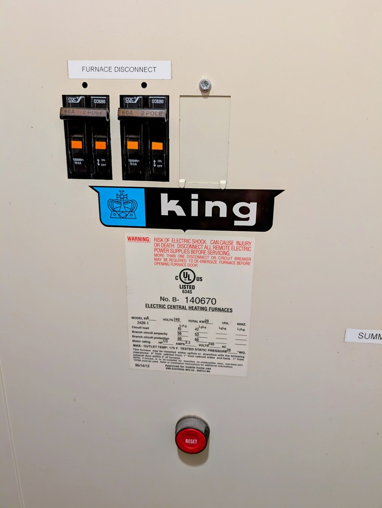
What is the model number ?
Or maybe post a good picture of the wiring diagram.
National - U.S. Gas Boiler 45+ Years Old
Steam 300 SQ. FT. - EDR 347
One Pipe System0 -
Do you have contactors in the system? What KW are the heaters. Take a picture of the control cabinet so we can see what is going on.
The tech you had was a dope. The typical 'I don't see a problem so there is no problem". You usually get that with someone who is not familiar with a system.
Troubleshooting is if you can't find the problem quickly
It becomes a process of elimination.
Instead of focusing on the problem, eliminate everything that is working ok until you find the problem.
Start by killing the power, trace every wire, check every wiring connection. If you have contactors look at the contacts. Check line voltage power and low voltage power. Ohm out the heating elements. Pull the elements out (carefully) and check for debris and obstructions. Amp out the heating elements.
0 -
or someone with management that is obsessed with closing tickets, not with if anyone's problem was actually solved
0 -
" Start by killing the power, trace every wire, check every wiring connection. If you have contactors look at the contacts. Check line voltage power and low voltage power. Ohm out the heating elements. Pull the elements out (carefully) and check for debris and obstructions. Amp out the heating elements. "
The problem I have with this technique, and also with what the tech you had did, is if you poke around and move stuff too much and seemingly randomly the problem may heal itself (again) with nothing new learned then you are doomed to work on it some other day when it eventually fails again. Wiring diagrams help, the better you understand the circuit the better strategic measurements can be made.
After a non contact visual inspection, I typically do powered up troubleshooting, I believe it is usually faster, more reliable method to find a defect. However stay safe and only use the method you are comfortable with, I have decades of experience.
National - U.S. Gas Boiler 45+ Years Old
Steam 300 SQ. FT. - EDR 347
One Pipe System0 -
This picture is what I already have in my phone. Will post a panel off shot tomorrow.
0 -
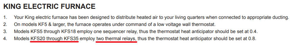
Well in my opinion the wiring diagrams in the manual are kind of lame. Looks like your unit may have two thermal relays not a sequencer.
When the unit acts up does the fan run with no heat ? Or nothing at all ? If nothing at all it may be something intermittent with the low voltage part of the control circuit or the absence of the 24 VAC control voltage.
 National - U.S. Gas Boiler 45+ Years Old
Steam 300 SQ. FT. - EDR 347
One Pipe System0 -
Seems like intermittent contact making in a sequencer or other relay in the circuit.
0 -
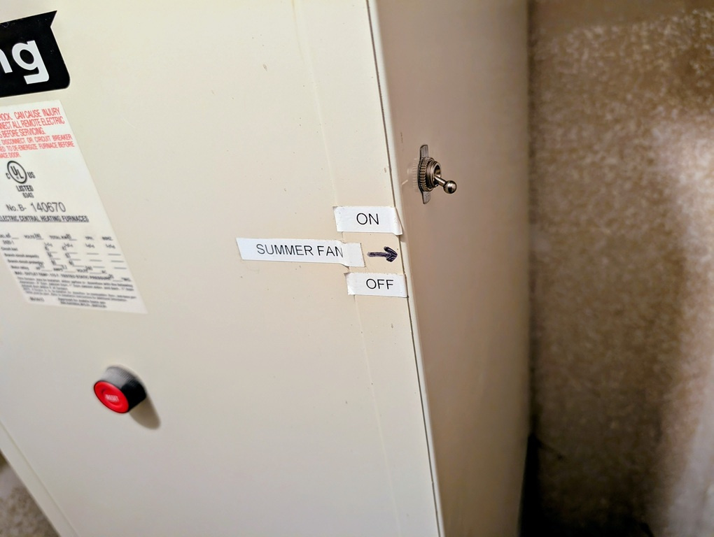
When the unit acts up there is nothing at all. However there is a manual summer fan switch on the unit that enables activating the fan and that works always. I never thought to try turning just the fan on with the thermostat. Something else to try if it fails again. No evidence of overheating or anything burning. Thanks for the wiring diagram!
0 -
I have chased these control problems several times.
The solution for me was to just replace all the sequencers with a Honeywell module that could control 3 elements and the fan.
Few places need all 20 KW (4 elements) to heat the house, even here in Northern Nebraska.
20 KW would overheat the furnace if all were engaged, due to lack of ductwork.
Also cooking the controls in the furnace, shortening their life.
Where are you located that you might need 20 KW of heat?
0 -
I would think a 20KW heater 68,000 btu would have something to prove airflow and a bunch of limit controls both auto reset and manual reset. yet the diagram shows nothing.
The diagram is very elementary flow diagram.
There is much more to the story here.
This thing takes about 85 amps.
It has to have some sort of protection.
0 -
is it cold when it won't turn on? if it is hot, could be some sort of limit tripping out.
0 -
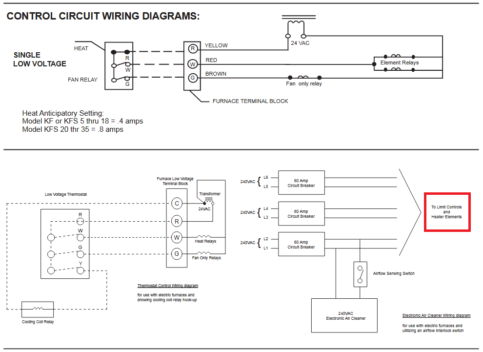
It appears the limits are on the high power part of the circuit (Red Box).
" However there is a manual summer fan switch on the unit that enables activating the fan and that works always. "
Can you hear the fan relay click ?
Is this switch on the thermostat or the heating unit or both ?
If on the heating unit as your sentence suggests I'd explore how that switch is wired into the unit and controls the fan, does it use the fan relay ? Since if it simply bypasses the thermostat's control of the 'G' wire inside the unit to energize the fan relay that may give you troubleshooting direction. If the fan control is in both places (thermostat and the heating unit) and normally works from both places when the unit is not acting up, then if it only works from the unit when it is acting up I would suspect a control power issue on the 'R' side of the thermostat. Since if the 'R' wire has an intermittent defect neither of the 'W' or 'G' will control the heating unit.
It all about understanding the circuit and doing normal easy stimulation to also help give troubleshooting direction and/or isolate the defect. The mechanical stimulus of flipping the units breakers may help indicate the defect is in the heating unit.
 National - U.S. Gas Boiler 45+ Years Old
Steam 300 SQ. FT. - EDR 347
One Pipe System0 -
First off thanks for all the help. Answers to questions.
We live in Seattle in a 2700 sq ft house. Temp here in winter rarely gets below freezing and seldom gets above maybe 65 deg F.
I don't think the unit is hot (overheated) when it doesn't come on but don't know for sure. If an overheat limiter was in play wouldn't it start to work again once the unit cooled off? Reset button has no effect.
When the unit fails to come on I can't hear anything because it's downstairs and thermostat is upstairs. But (again) fan works with manual switch always.
Today I tried turning just the fan on at the thermostat and that function doesn't work. I assume this is because there are only 2 wires from thermostat to the heater? And maybe that's why the manual fan control was added on? Those 2 thermostat wires look like they're probably as old as the house but as long as they're intact not sure what could go wrong there.
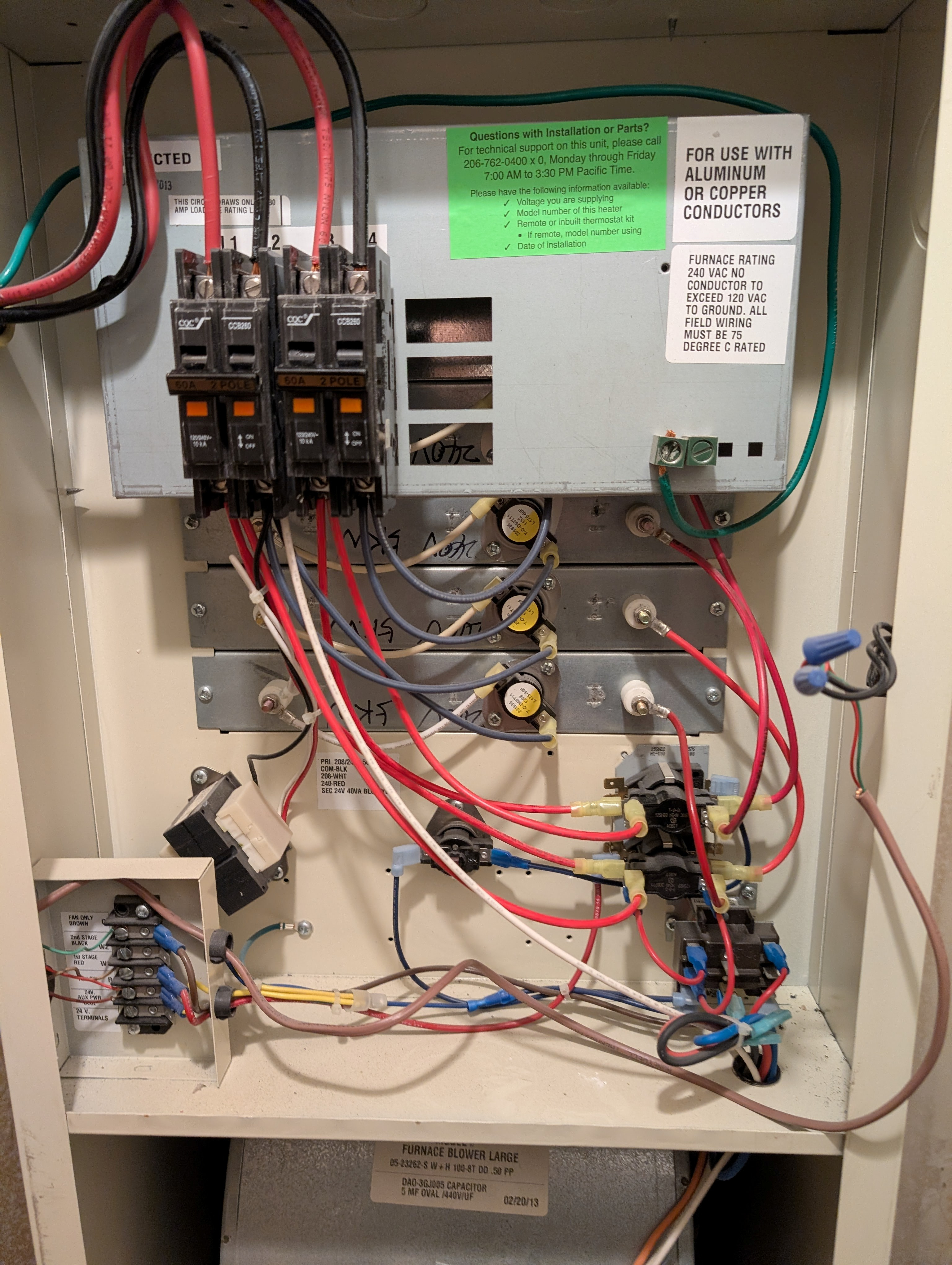
Here is an external picture of the unit front panel. The reset button doesn't do anything when the unit doesn't come on.
And here's the front panel off.
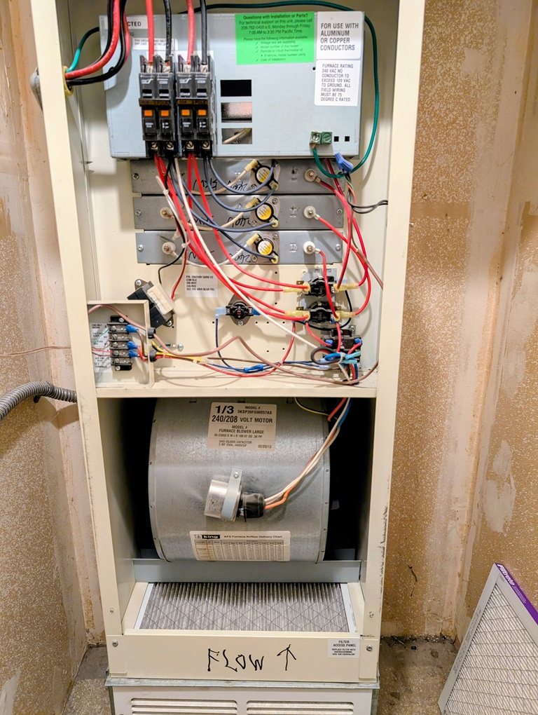
I think there's enough detail there to see all the components. I have close ups if not. Note spliced in wiring for summer fan.
Anyway the heat is currently working. If it goes out again I could detach one of the thermostat wires (the red or white one?) and check for continuity there? If it's good and showing 24v then I know it's a relay or sequencer?
And that's the sequencer just below the heater elements at lower right? Turn off power, remove old sequencer. Swap out wires one by one to new sequencer. Attach new sequencer. Turn on power. Is it any harder than that?
Again thanks for the help!
0 -
you could also jumper the t-stat wire at the furnace when it isn't running and see if it comes on.
0 -
how are the sequencers wired, are they all wired to the same control or are the cascaded with eachother?
0 -
You mean jump across the red and white wires at the low voltage terminal block? I actually think that's what my tech may have done which caused it to come on.
0 -
yes
0 -
if the red and white separately connect to each sequencer then none of the line voltage stuff is common.
0 -
Can you take a photo of this area so the wires can be seen much better or sharper ? Maybe from different angles also.
 National - U.S. Gas Boiler 45+ Years Old
Steam 300 SQ. FT. - EDR 347
One Pipe System0 -
Isn't there a complete wiring diagram you can post a picture of?
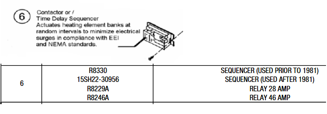
I would probably just replace the sequencers they are just bi metal switches and with everything else in the picture the sequencers are the most likely part to fail
0 -
sequencers, sequencers, sequencers almost everybody is betting on the sequencers.
However @kadini stated
" When the unit fails to come on I can't hear anything because it's downstairs and thermostat is upstairs. But (again) fan works with manual switch always. "
So the sequencer(s) control the fan in normal heat mode ??? It may, looks like the lower sequencer has extra wires.
And where is the isolation between heat mode fan and summer mode fan. It appears the thermostat only has two wires and the summer fan switch only has two wires.
Is there a better wiring diagram on the back side of the cover ?
National - U.S. Gas Boiler 45+ Years Old
Steam 300 SQ. FT. - EDR 347
One Pipe System0 -
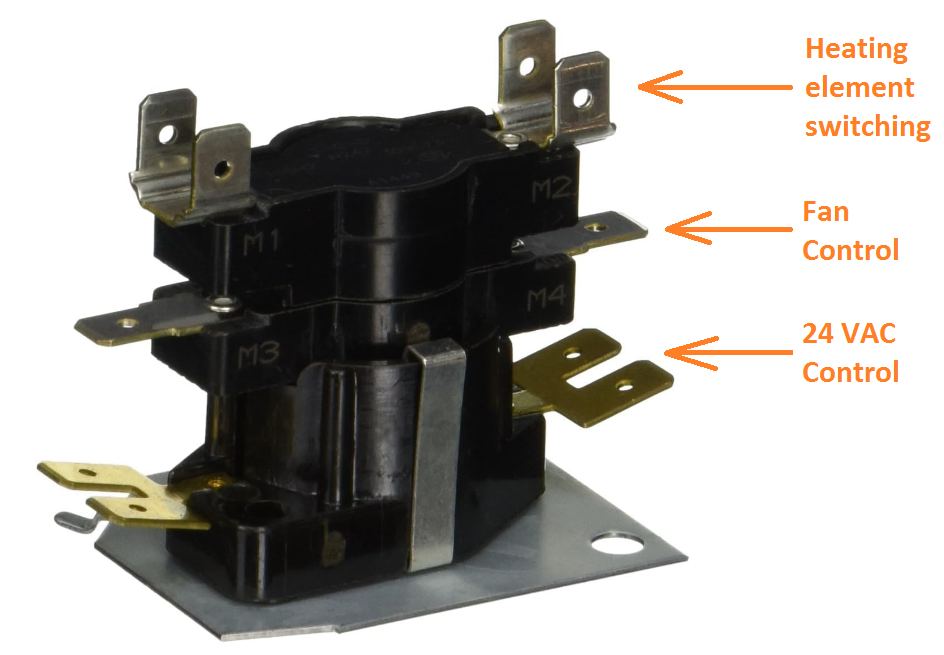
Since I can't see all the wires very well, I presently suspect this is the way it works. When the 'R' and the 'W' wire on the thermostat closes it energizes both heaters inside the sequencers (you have two of these units with the control heaters paralleled, only one is pictured here). The 24 VAC control power is applied to the lower brass looking contacts in the picture labeled 24 VAC control. This (depending on the sequencer design) will close the two independent sets of contacts above with some delay, the upper M1, M2 contacts switches the heating elements, the middle connections M3, M4 (Fan Control) energizes the fan motor.
So in my opinion (with the information I have) if no fan AND no heat from the heating elements on a call for heat I would be looking at the 24 VAC control circuit. The 24 VAC power from the transformer needs to get to the sequencer heaters. If the control power does not get to the sequencer heaters, nothing will happen.
If the 24 VAC control was good and getting to the sequencer's heater terminals, but a sequencer had a bad contact I suspect you would have power only to some of the heating elements or no fan, but not both functions failed.
If for example your lower sequencer had an intermittent heater, I suspect you would have power to the heating element from the activation of the other sequencer and no fan. If the heating elements were powered with no fan I suspect that would eventually trip the high temperature limit requiring a reset.
Presently I suspect a bad connection or crimp connection in the 24 VAC control circuit.
Other things I suspect: Possibly you have a two speed fan motor, heat mode may be slower than the summer mode. When 'R' is closed to 'G' by the added Summer Fan switch it energizes the "Fan Only Relay" for the higher fan speed.
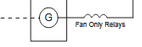
The "Fan Only Relay" when not energized the NC (normally closed) contacts are closed which simply connects the sequencer fan control contact to the slower motor speed wire. When the "Fan Only relay" is energized it applies power to the wire for the faster fan speed. The "Fan Only Relay" when energized may also disable the control for heating. I can't see the "Fan Only Relay" wiring very well.
One sequencer example, the timing of yours may be different.
 National - U.S. Gas Boiler 45+ Years Old
Steam 300 SQ. FT. - EDR 347
One Pipe System0 -
Without a wiring diagram its a guess. You can't see everything in a picture.
 1
1 -
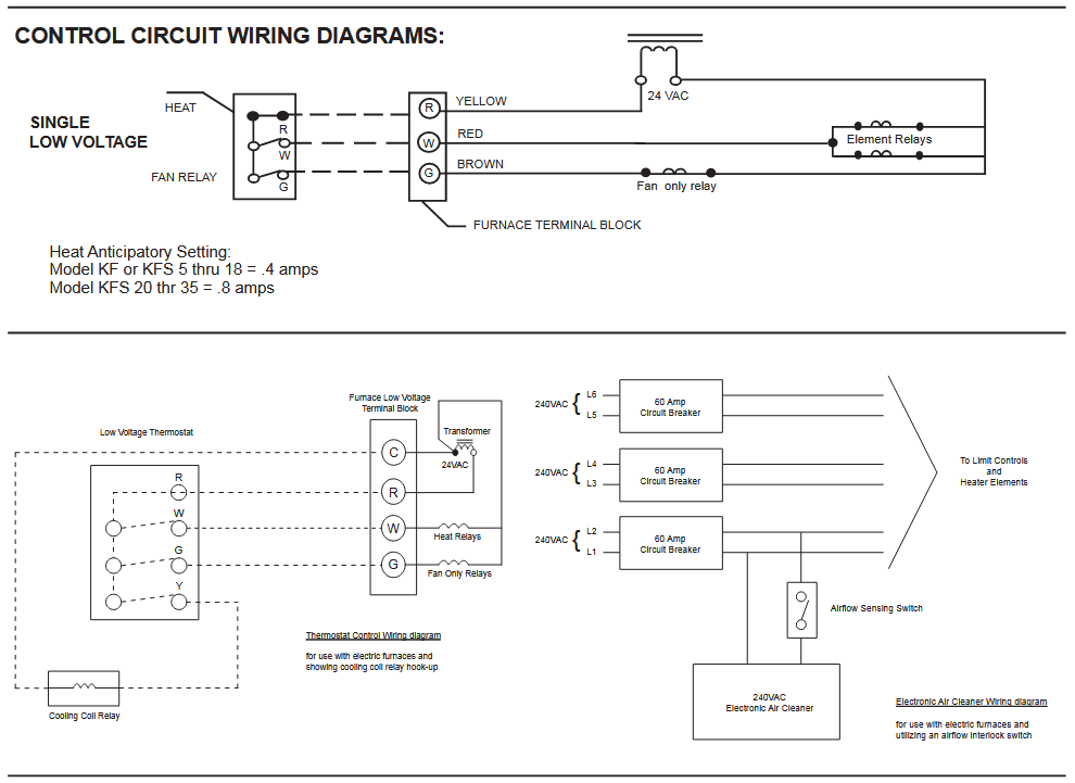
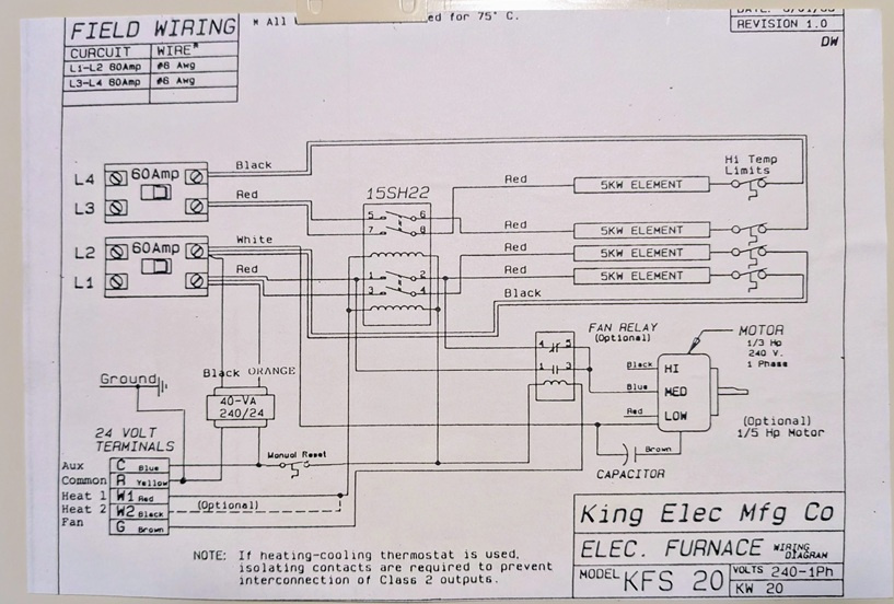
Here's the wiring diagram on the back of the panel.
Here are the wires connected at the 24 volt terminal. Doesn't seem to match the wiring diagram exactly (and upside down?). From top to bottom in photo.
1: Green wire from summer fan switch
2: Nothing
3: Yellow wire from thermostat (colors on last 12" of thermostat wires discolored due to age or heat?)
4: Bright red wire from fan only switch and dull red wire from thermostat
5: Nothing
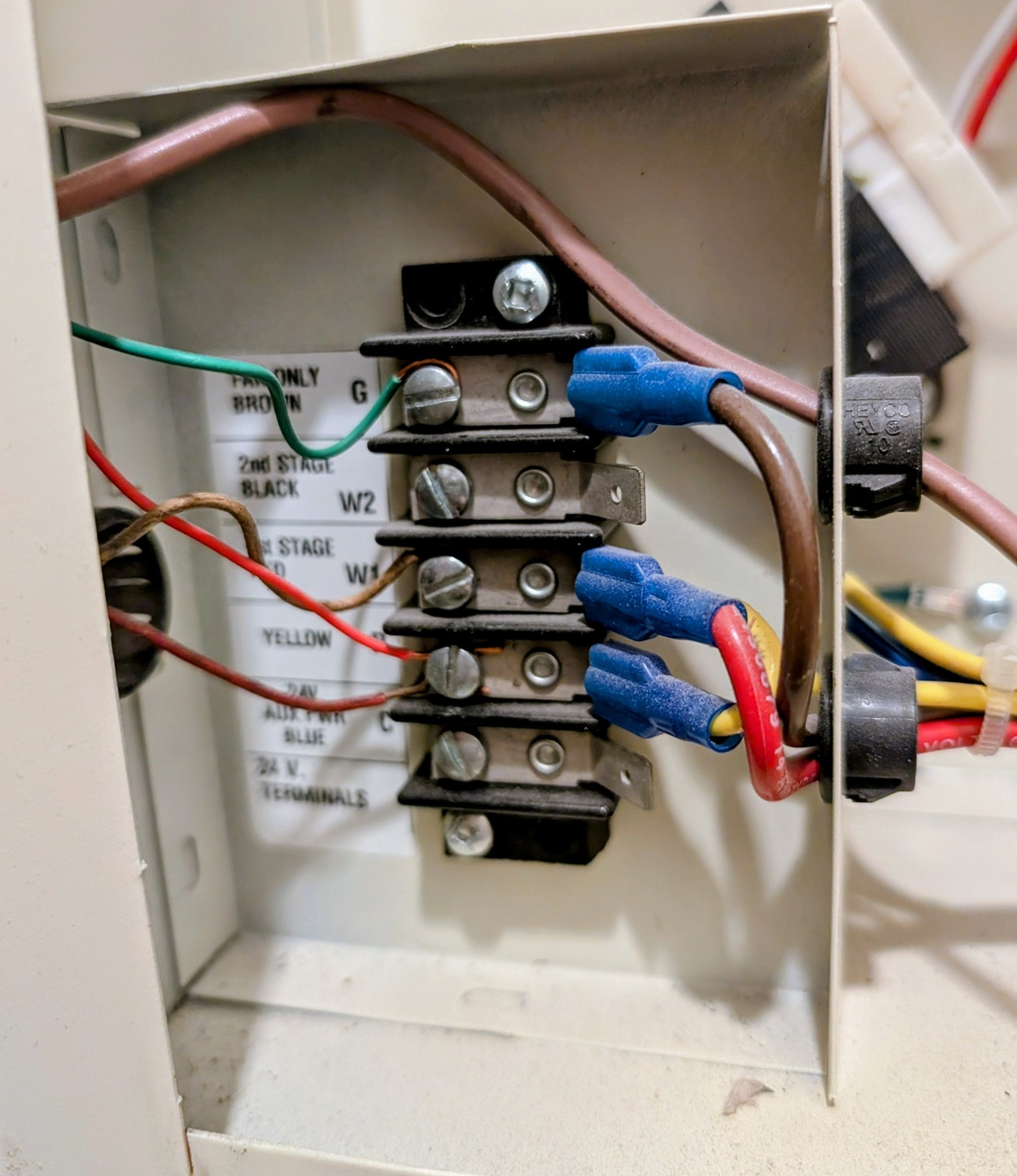
More to come.
0 -
The sequencers are in parallel, so either the sequencers aren't the problem, or it has been running off of one sequencer for a long time and the second sequencer finally failed.
0 -
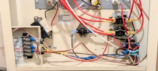
Here are some pictures which I hope make actual physical wiring clearer. Question though, does the actual 24v wiring not match the wiring diagram? Should 24v yellow wire be swapped with red wires?
Overview
Close up lower left
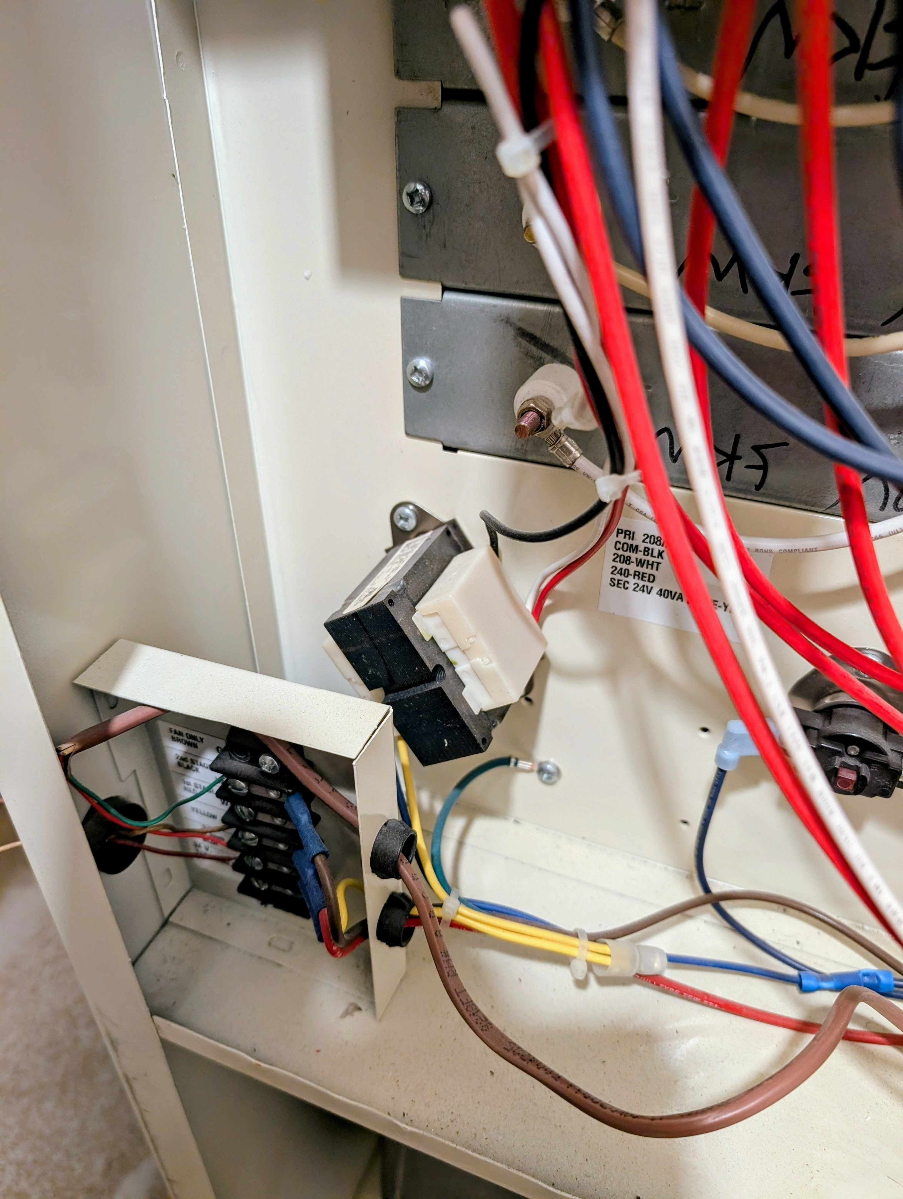
Closeup lower right
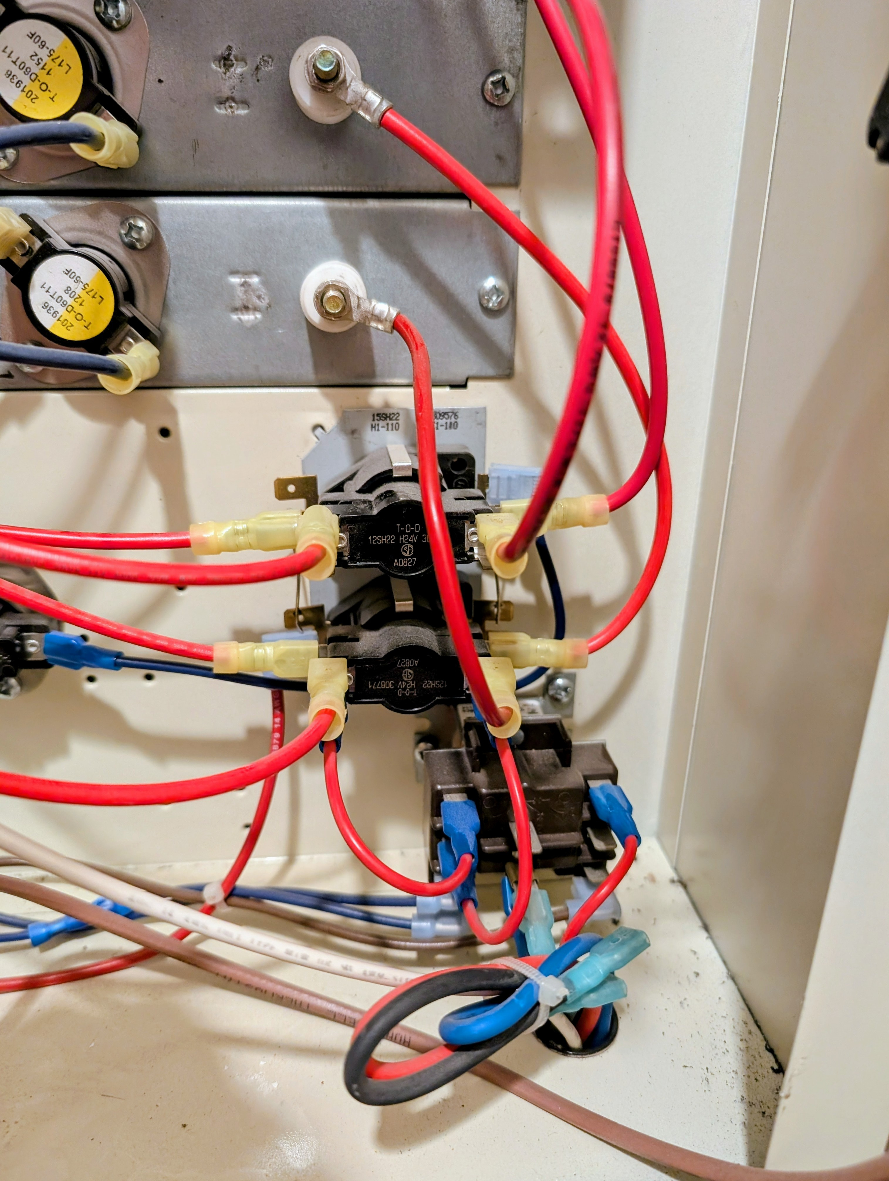
If this doesn't do it let me know but physical constraints make improvements unlikely.
Final question, if unit fails to come on again what diagnostic steps should I take? Should I disconnect the yellow wire or the red ones at the 24v connections to see if power is getting to the thermostat? Or am I misunderstanding what needs to happen?
Thanks.
0 -
I do like wiring diagrams.
24 VAC control wiring. When the thermostat is off — not calling for heat — check and see if you have 24 VAC between the terminals marked R and W1. OK? Turn the thermostat on. Now you should have 0 volts between R and W1. OK so far?
You also seem to have a fan only control. When that switch is off and the heater isn't running, check for 24 VAC between G and R. When that switch is on, that should be 0 volts.
When the fan switch is on, the fan should run regardless of the thermostat setting. If the fan switch is off, the fan should only run if the thermostat is calling for heat.
Now the "sequencer" (I'd call it a contactor, but that's me). I see nothing to suggest that there is a thermal or actual sequencing function here; if the wiring diagram is standard, and it looks it, that unit is two relays, each two pole single throw normally open. Now this test is also live — but instead of poking at 24 VAC, you are poking at full load voltage, so be careful. There are studs for the wires from the sequencer to the elements. With the thermostat calling, measure the voltage between the lower pair of studs and the voltage between the upper pair of studs. Both of those measurements should be exactly zero. If there is a voltage difference — even a very small one, double check — but if the difference stays, there is at least one bad contact in the sequencer and it needs to be replaced. At the other end of the strips there are similar studs with white wires. Again between the lower two and also between the upper two. Both of those measurements should be exactly zero. If there is a difference (and it may be full line voltage) one of the two strips in the pair is open or its corresponding thermal limit switch is open.
One further comment. You are poking at 240 VAC power fused at 60 amperes. That can do a huge amount of damage to you or the equipment if even a momentary short is made. Be sure you know what you are doing. Use protected probes.
Br. Jamie, osb
Building superintendent/caretaker, 7200 sq. ft. historic house museum with dependencies in New England0 -
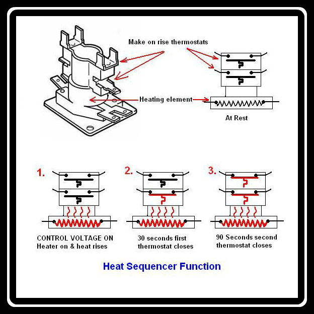
They are sequencers and this is the timing
 0
0 -
OK, @mattmia2 — but now I would like an explanation as to how, in fact, they perform any kind of sequencing. The circuitry shown on the wiring diagram does not show any provision for sequential operation of the contactors.
You can, if you like, send it to me directly to avoid muddying up this thread — but I really do want to know.
Br. Jamie, osb
Building superintendent/caretaker, 7200 sq. ft. historic house museum with dependencies in New England0 -
The fan switch is wired to R & G on the terminal strip so the switch pulls in the fan relay which is in the lower right of the panel. Thermostat has no control over fan directly it runs off the sequencer . One sequencer starts the fan and delays the shutdown when the stat is satisfied
It looks to me there is an extra wire on the fan relay. The three reds are power to the fan relay 1 no and 1nc contact and common to the fan motor which is correct., Brown and blue are the 24volt to pull the relay in which is correct. But it looks like another wire is on the lower middle contact …can't see the color or trace it Just curious as I don't see it on the diagram.
The thermostat is wired between r and W1 on the terminal strip. This unit is 1 stage heat.
Take your meter and check from the R terminal on the strip to the blue grund wire grounded to the panel you should have 24 volt s all the time with the power on.
If it will not start check from the w1 terminal on the strip to the blue ground . You should have power there when tthe unit starts with the stat calling. If it will not start jump w1 to r on the terminal strip.
No danger there its all 24 volts
The thermostat is wired between R & W1. Since you say the fan always starts and the heat does not your problem is the thermostat or the sequencers as there are 2 red wires coming off of R 1 to the stat and 1 to the fan switch. Rule the thermostat in or out checking what I mentioned above first. If the stat is I would suggest the sequencers are next
The other thing is the blue wire bottom of the panel has a crimp butt splice connector. It looks suspicious and is not factory so give it a pull
0 -
@Jamie Hall not an expert with sequencers but 2 wires go to a "pan heater" which is basically the coil. When it gets powered the bimetal heats and then closes or opens a contact, When power is taken off there is some delay before action takes place. Its sort of a cheap contactor with a time delay built in. You can get them will all different timings
0 -
So the coil in the diagram isn't a relay coil, but a heater? Fair enough… But I have to admit from an engineering standpoint I don't like it — unless the bimetal has one heck of a snap action and a good long throw driving the contacts both ways, that puppy is going to arc and burn the contacts. I'd at least like to see suppressors across the contacts…
Br. Jamie, osb
Building superintendent/caretaker, 7200 sq. ft. historic house museum with dependencies in New England0 -
it might be throwing a contact from the heater/snap disc that is energizing a coil too. i just glanced at the cut sheet, i didn't read it thoroughly.
but the takeaway here is that both are in parallel off the controls so either the controls aren't energizing them, or one went bad and it has been operating at half power for a while and it wasn't noticed until the other sequencer failed.
0 -
To me 20kw should be two stage IMHO. Pretty big wallop to start all at once. Running full bore in the spring and fall doesn't make sense to me.
Could be easily changed by putting in a two stage thermostat
0 -
when it does run, do all 4 heaters heat?
0


Categories
- All Categories
- 87.6K THE MAIN WALL
- 3.3K A-C, Heat Pumps & Refrigeration
- 59 Biomass
- 429 Carbon Monoxide Awareness
- 124 Chimneys & Flues
- 2.2K Domestic Hot Water
- 5.9K Gas Heating
- 119 Geothermal
- 168 Indoor-Air Quality
- 3.8K Oil Heating
- 78 Pipe Deterioration
- 1K Plumbing
- 6.6K Radiant Heating
- 394 Solar
- 16K Strictly Steam
- 3.5K Thermostats and Controls
- 56 Water Quality
- 51 Industry Classes
- 50 Job Opportunities
- 18 Recall Announcements