Air purging with poorly placed coin vents
Comments
-
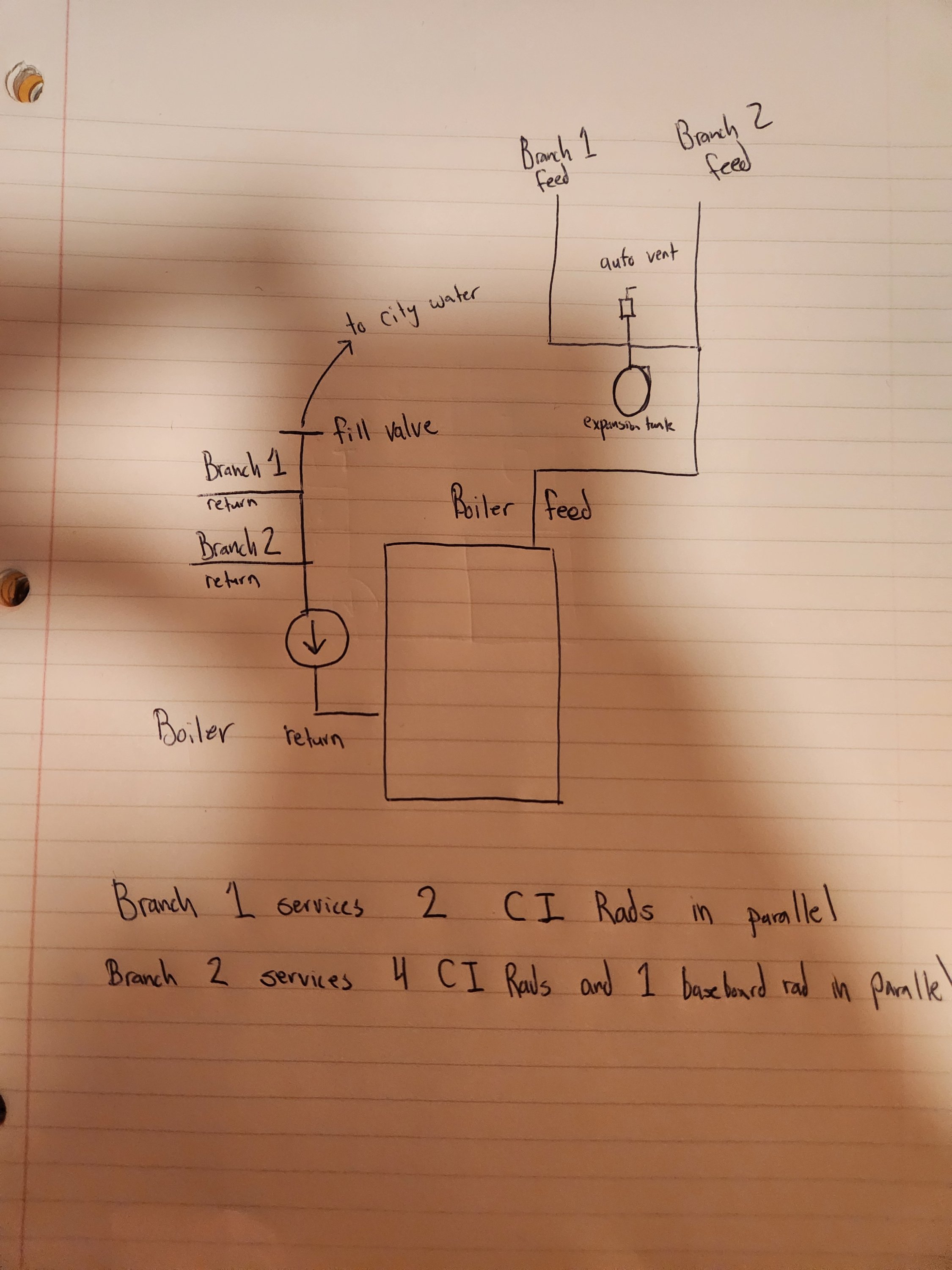
@EdTheHeaterMan See the attached diagram for a general idea of my piping. From what you described, I should install the valve with a drain on the feed side of my boiler at the start of the baseboard loop. Why does it matter what side of the loop the drain is located on for purging? When you purge in this way by using pressure to push the air, why is there a guarantee in the direction of flow? I thought a circulator pump would control the direction of flow, but in this case, we are using the building system pressure to purge, so wouldn't the water level just rise equally in both the return and feed side of the piping as pressure builds? I picture it more as the water builds, it pushes the air up. When you open a valve, it acts as a relief for the pressure and all of the fluid (whether it is air or water) will then flow towards that relief (path of least resistance).
Yea the issue is the piping near the boiler is all very old and last year when I was working on capping some of the piping, it was really difficult to work with. I had to break a lot of stuck sittings and be extremely careful not to damage old threads. There are sections with newer copper piping (I can tell by the propress fittings and tape. I don't want to pick up a job like repiping near the boiler till I'm ready to upgrade my boiler. I might consider adding zones next year along with toe kicks, but I'm currently working on finishing a kitchen remodel. I was refilling the boiler because I wanted to add a TRV to an upstairs rad that had no valve and last year I noticed my PRV was slow leaking. This caused me to top off the boiler every other weak to maintain pressure.
0 -
Also, are there any tools that can be attached to stuck coin vents that are stuck in the upward position to prevent them from spraying water everywhere (e.g. hose) while you purge air from a CI rad?
0 -
So my diagram is close. With your diagram I can see some problems with water pressure increasing without a reason. but there is a hidden reason.
A can't see were the baseboard is connected using your diagram, but I assume that it is connected to pipes where a radiator was removed. So I just added it at a random location where a radiator may have been removed at some point before you moved in.
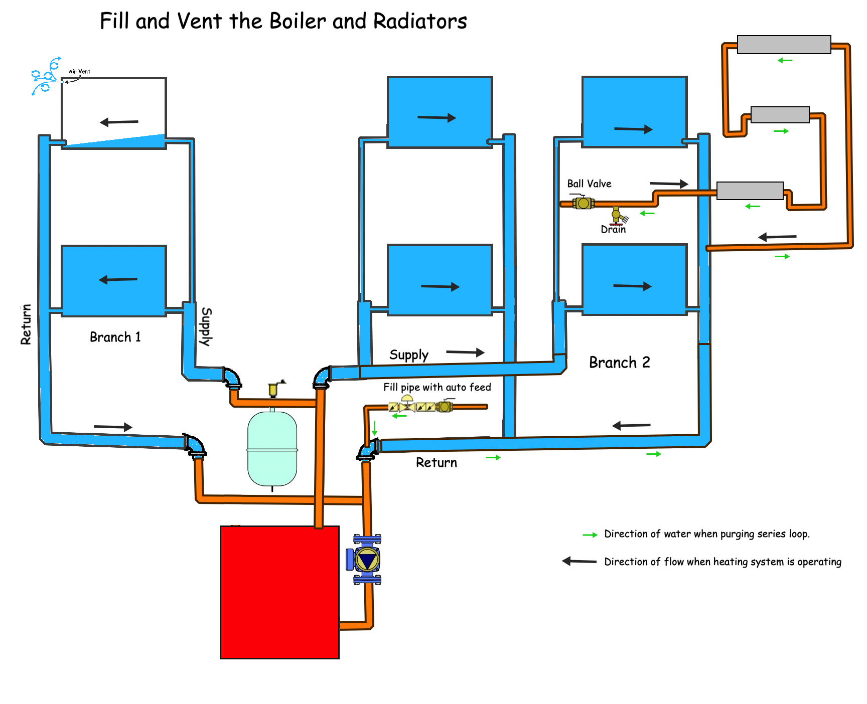
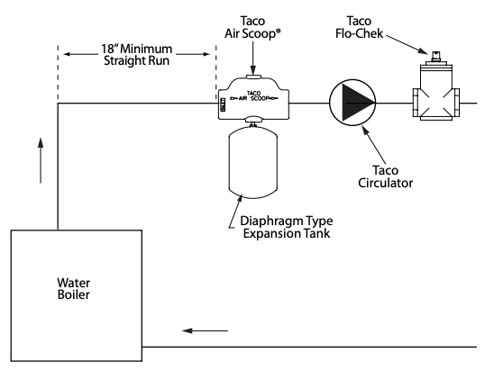
If you zoom in on the supply pipe where the old radiator was removed and the series loop was connected, you can see the copper pipe has a ball valve with a boiler drain valve close to it. This is your purge station for the series loop. I put it this way because you indicated that your fill valve is connected to the return pipe close to the branch 1 and branch 2 pipes connected to the boiler. The fill valve is connected to the inlet side of the pump according to your diagram, so I added it just before the branch 1 and branch 2 pipes Tee fitting connection to the circulator pump. The order is: boiler feed, then branch 1&2 returns, then the circulator pump, then the boiler return opening.
Are you following me so far?
On the supply side of the boiler you have a Tee fitting connection that goes to branch 1 and branch 2. The expansion tank is connected to the horizontal pipe after the Tee fitting to branch 1. I think I got that right from your diagram. Or close enough
Now comes the mysterious pressure increase problem.
The expansion tank also known as the point of no pressure change PONPC is at the supply pipe near the boiler. The circulator is on the return side of the boiler and it pushes the water into the boiler towards the PONPC. Here is an illustration of that exact situation that I used in my one day seminar that I taught for the Eastern Heating-Cooling Council.
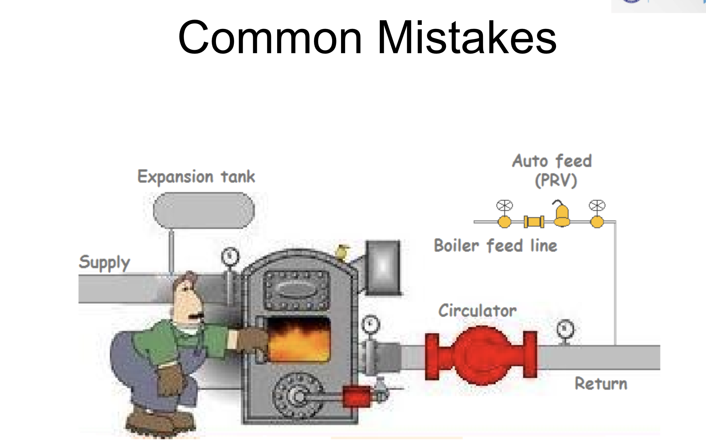
In this illustration I show a circulator pump on the return with the water feed valve entering the system on the inlet side of the pump (just like your diagram) then the boiler gets the water from the discharge side of the circulator and that water gets pushed to the supply side of the boiler where the expansion tank is located aka PONPC. This illustration has gauges placed everywhere to see what happens when the pump comes on.
Now when you fill the boiler with cold water and the expansion tank has 12 PSI air pressure in the tank when there is no water pressure connected to it. All the gauges near the boiler will read 12 psi once the system is full of water and there is no air left in the pipes, radiators or boiler. (only air is in the expansion tank cushion. Let's say that the circulator has the ability to change the pressure by 6 PSI. That means whatever the inlet pressure is, the outlet pressure will be 6 PSI higher whenever the pump operates.
Now look at the pump and turn it on. The PONPC gauge will stay at 12 PSI. The pump will force water into the boiler and lets say the pressure drop thru the boiler is 0.5 PSI. That means the pump outlet pressure will be 12 PSI plus the pressure drop thru the boiler for a total pressure at the outlet of the pump of 12.5 PSI.
If the pump has an outlet pressure of 12,5 PSI and the inlet pressure will always be 6 PSI lower, then the inlet pressure must drop to 6.5 PSI. That pressure will increase as the water moves through the boiler pipes and the friction loss will eventually increase pressure to 12 PSI at the expansion tank. The fact still is that the first time the pump operates the pressure at the inlet will be 6.5 PSI and the autofill valve is set to maintain 12 PSI. So what happens when the water pressure in the pipe drops to 6.5 PSI at the auto feed? You guessed it, the auto feed will add water to get the pressure up to 12 PSI while the circulator is operating.
Now what happens to a system that is full of water where the only air cushion in the system is in the expansion tank? That extra water gets placed into the expansion tank and that makes the pressure increase to 18 PSI. That is because the 12 PSI return water going into the circulator gets 6 PSI added to it by the circulator pump. Now you have 18 PSI on the discharge side of the pump. That 18 PSI extra water compresses the air in the expansion tank to 18 PSI and you have in effect made the expansion tank a smaller tank because there is less air to absorb the expanding water as the system heats up. This only happens once when the circulator pump turns on the first time after filling the system.
Say the winter gets colder and the water temperature stays hotter longer in the system, you can actually get the water in the boiler to approach 30 PSI on the coldest days. That is because the 18 PSI system water pressure expands into the tank that can not accept all of it so the pressure increases until there is a drip at the pressure relief valve. As the water leaves the system by the relief valve, more water is added after the system cools down and the process continues until the relief valve fails completely and no one knows why the pressure goes up so much. There must be a leak somewhere letting water in the system. OR you have a flaw in the design that makes the system over fill just by turning on the circulator pump to heat your home
Edward Young Retired
After you make that expensive repair and you still have the same problem, What will you check next?
0 -
@EdTheHeaterMan The diagram is mostly correct. The only incorrect parts is the piping after the branches, but it's mostly correct. It gets the point across. What is the mysterious pressure problem in reference to? I don't have an auto fill valve. I manually fill the boiler and turn off the fill valve when the circulator is running otherwise I'd have an open system. My PRV leaks when the fill valve is closed, so I don't believe it's tripping because the system is over pressure (especially since I was watching my pressure gauge all last winter and it was well below 15psi). The pressure loss was from the PRV slow leaking. I put a pan under the PRV and it would collect water all last winter and I could watch the slow leak happen. I believe I started the slow leak after I tested the PRV during my boiler fill last year. I learned afterwards that doing this on an old PRV is risky because they might not seat well again. I replaced the PRV and the leak has stopped, so I don't think I'll need to refill the boiler all winter.
0 -
No Auto feed valve? Then that problem I described will not affect your system. But now you know that you should not add an auto feed at that location.
You should operate your relief valve at least once per year to make sure the water ways are clear. When you operated your relief valve and it failed to close, then it was defective. You did the correct thing by replacing it. I had a feeling that you may have had an auto feed and the relief valve leak may still be a problem. It sounds like you have this under control now.
I hope the diagram for the purge station was helpful. As you already know, venting using a coin vent or loose key air vent does not work on a series loop, purging is the way to go.
Edward Young Retired
After you make that expensive repair and you still have the same problem, What will you check next?
0 -
@EdTheHeaterMan Can you explain why it matters what side the drain valve is located on the series loop matters in relation to the fill valve? I thought that while filling, water wouldn't have direction, it would be at the same height above the ground in both the return and feed as you fill or is it because the drain should be open during purging a series loop, so this creates a pressure differential and the water will have a path it follows?
Also, do they make anything for catching water from the coin vents during purging, like vinyl tubing over the output port?
0 -
@EdTheHeaterMan I get it now I think. It needs to be on the opposite side as the fill valve because that should be the longest path to the drain in that loop. If it was on the same side, it would drain water and air would be stuck on the other side of the valve, unable to be purged.
0 -
There is no difference. It will work in either direction in most cases. For your situation, as you have drawn it, it will work both ways. Sometimes, however, a replacement circulator may have an internal flow check valve. If you ever need to repair or replace a circulator and it happens to have an IFC and it is left in place, you may not get the water to flow in both directions. My diagram accounts for that.
Not knowing if there are other flow check valves in an old system like yours makes for interesting piping problems. My diagram accounts for that too.
In your situation, it will make little difference if you add the purge station to the supply or the return of the series loop. Just did it that way in the event someone has a more complicated piping system than you have and looks at this post to solve their problem in some future time
Edward Young Retired
After you make that expensive repair and you still have the same problem, What will you check next?
0 -
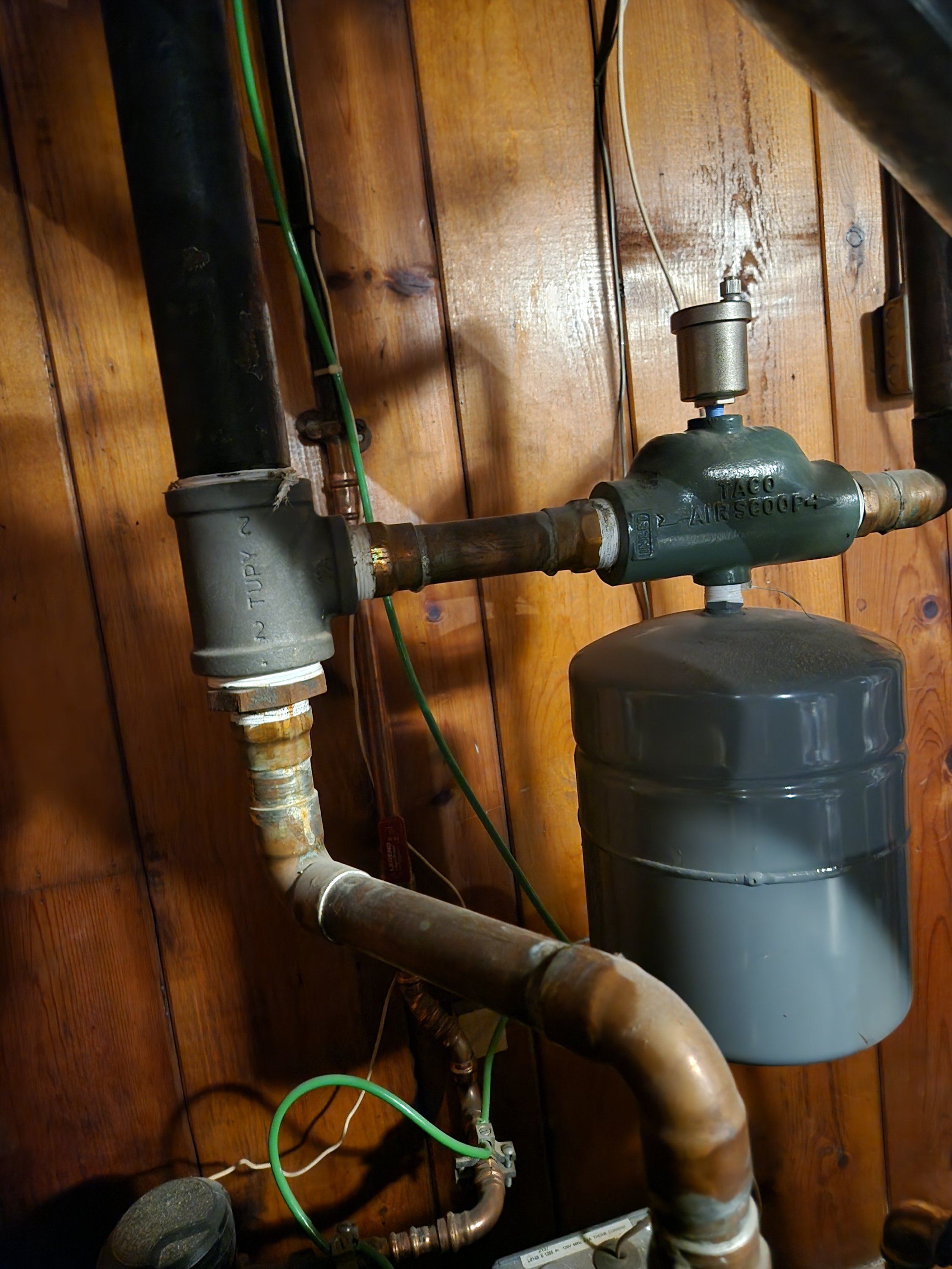
@EdTheHeaterMan Any idea why a plumber would've plumbed the expansion tank and auto vent like they did? I haven't been able to wrap my head around that decision making. Seems like it would be fairly ineffective because it doesn't capture all of the flow before it splits.
0 -
is the pipe size for the air separator smaller? smaller diameter separators are less expensive and easier to find. it is somewhat less effective but as long as that zone gets used the air will eventually find its way there.
0 -
The expansion tank can be placed anywhere in the system on a single zone system. That expansion tank location is fine where it is, unless it is attached under an air scoop of some kind. Then the decision may have been because it was the only horizontal pipe on the supply side. I would have redesigned the near boiler piping so the scoop would handle both branches. You never know the level of incompetence your previous owner and their contractors have until you see stuff like this.
Edward Young Retired
After you make that expensive repair and you still have the same problem, What will you check next?
0 -
@EdTheHeaterMan It is on an airscoop. It most likely is the only horizontal short stub that was suitable or maybe this all use to be on a single pipe and this was the only way the plumber could install the expansion tank without a complete redesign. The near boiler piping is a kluge of all types of different fittings.
 0
0 -
Seeing that picture tells me that the plumber can not read simple instructions or can read a tape measure. In the installation instructions and on this Submittal sheet it clearly states that there must be at least 18" of strait approach pipe. this is to insure laminal flow in the air scoop so the air bubbles will get "Scooped" up to the upper chamber of the device so the air vent can release the air.
So the fact that the air scoop is only serving one branch of the system is not accurate. It is actually serving less than 1/2 of the 1/2 of the system, since the turbulence of the tee fitting will cause a lot of the air to just flow past the scoops inside that device.
I would not worry about this until you decide top replace the boiler and properly redesign the near boiler piping to eliminate air problems more efficiently.
Edward Young Retired
After you make that expensive repair and you still have the same problem, What will you check next?
0 -
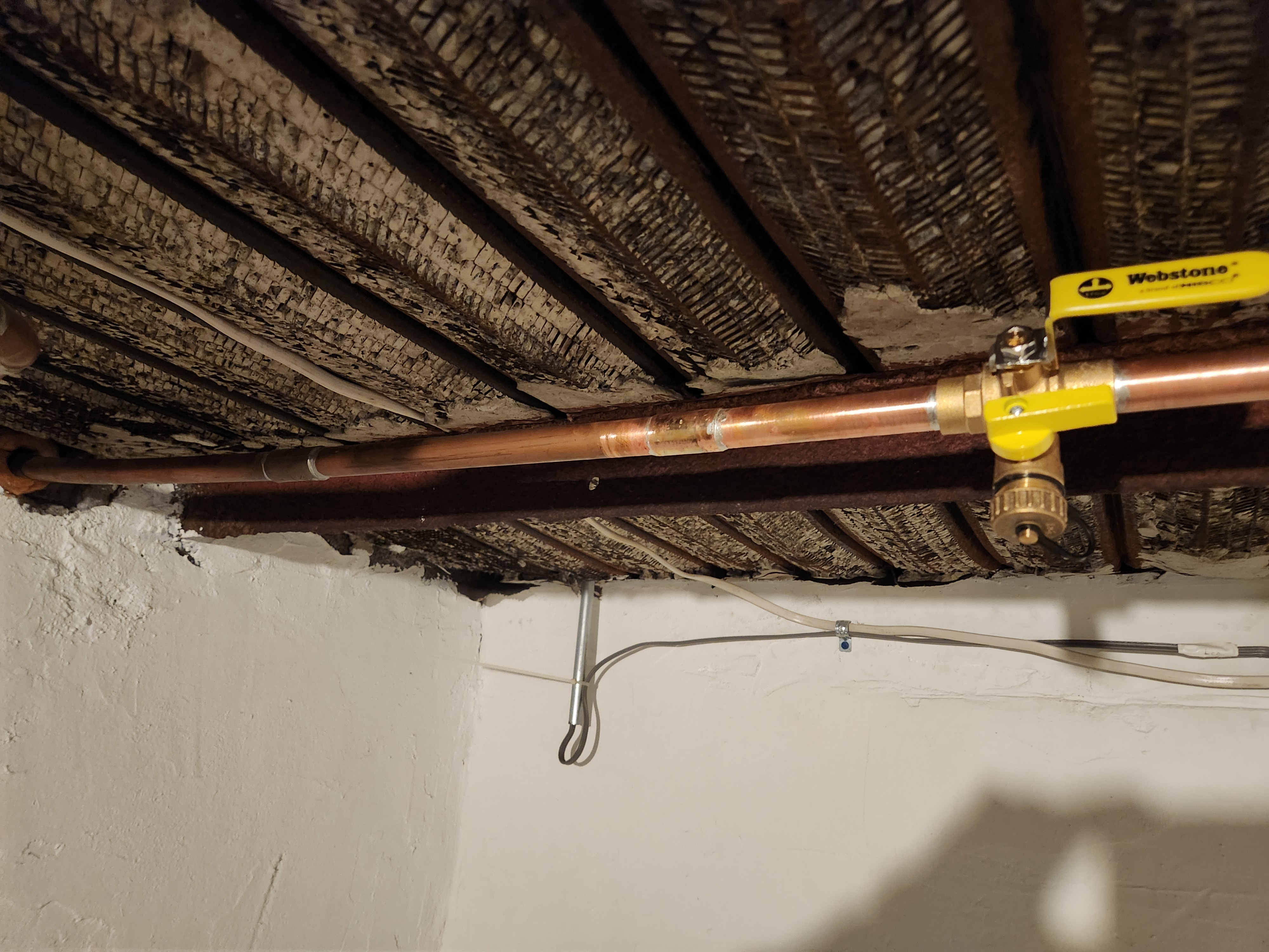
@EdTheHeaterMan I finished adding my drain valve to the loop and it got me thinking about these ball valves. Can I use a valve like this to balance the series base board loop relative to the CIs rads that are piped in parallel? For example, if I partially opened the valve pictured, would it be an effective way to balance the heat output of the loop since I'm controlling flow by closing the valve partially (e.g. a proportional control where heat output is proportional to the valve position).
 0
0 -
Actually you can if the baseboard loop is getting too hot. But I have found that baseboards that replace CI radiators (like may be the case in your situation) often do not heat the area enough. Throttling down a series loop that was added to a parallel system will not increase the amount of heat output, it will only reduce it.
Edward Young Retired
After you make that expensive repair and you still have the same problem, What will you check next?
0 -
Adding a purge valve is a great idea. Best if installed as close to the boiler as possible on the return(s). This will help in purging the mains manually. Then manually purge each branch of the mains at the radiators. It could help tremendously if you got rid of that old technology air scoop and replaced it with a microbubble air separator.
0


Categories
- All Categories
- 87.6K THE MAIN WALL
- 3.3K A-C, Heat Pumps & Refrigeration
- 59 Biomass
- 429 Carbon Monoxide Awareness
- 124 Chimneys & Flues
- 2.2K Domestic Hot Water
- 5.9K Gas Heating
- 119 Geothermal
- 168 Indoor-Air Quality
- 3.8K Oil Heating
- 78 Pipe Deterioration
- 1K Plumbing
- 6.6K Radiant Heating
- 394 Solar
- 16K Strictly Steam
- 3.5K Thermostats and Controls
- 56 Water Quality
- 51 Industry Classes
- 50 Job Opportunities
- 18 Recall Announcements