GV90+ the piping.

So if you look in the piping schematics from WM, there is no arrangement that allows the hot water heater to be fed from the primary loop except in the multi boiler arrangement and it shows as you see in the screen shot.
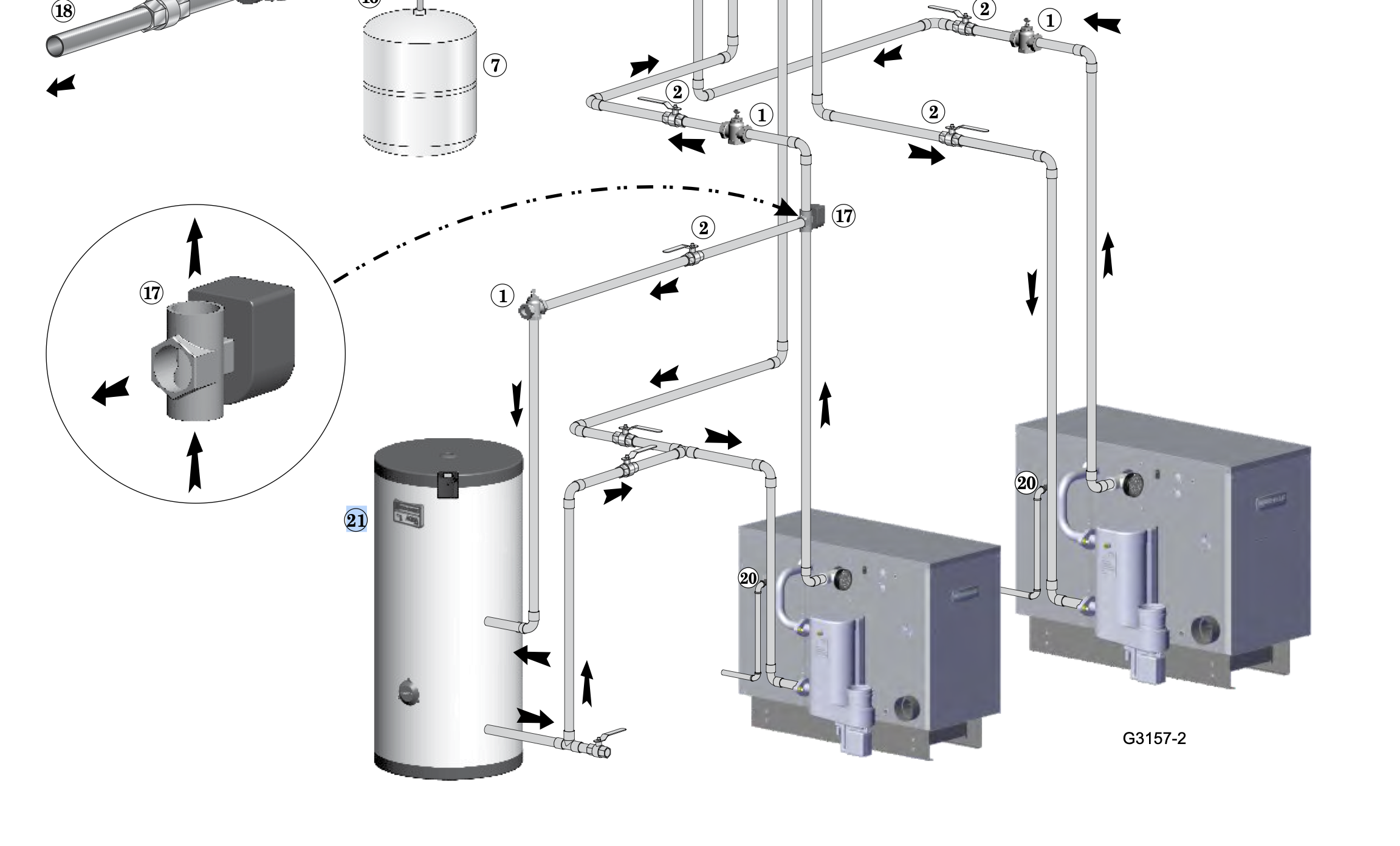
So I called and explained i am only using one boiler, and replacing an WM Ultra. The arrangement of piping is a tee on both the supply and return before the closely spaced tees.
I asked if I could do a set of closely spaced tees on the supply before closely spaced tees for the secondary loop, and was told NOTHING is allowed in the primary loop! I asked why they felt that a 3 way valve is better than two closely spaced tees as we see in the pic above and he was not hearing it. If you used a 3 way the customer would be left to ensure the right amount of flow could make it through the HX and that the internal pump to the boiler could handle it!!
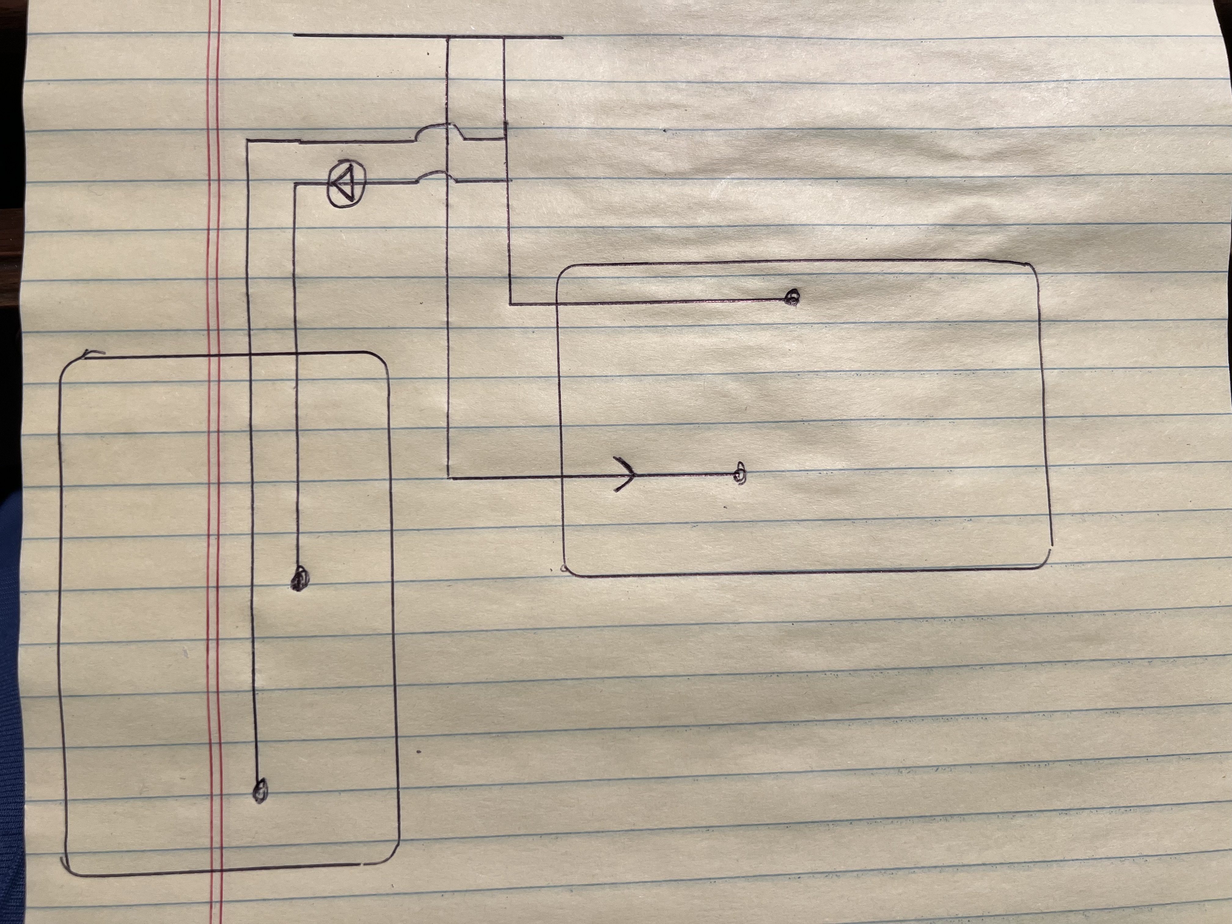
Anyone see a conflict with just popping a set of closely spaced tees in after the supply and before the closely spaced tees? Im not asking for permission, I understand that if I do a piping arrangement unlike what was allowed by WM I will be left to own it!! But, what I am asking is based on what is drawn, and knowledge of the internal piping of that boiler, you think it'll work?
Montpelier Vt
Comments
-
On your diagram, what control is there as to how much flow goes through the indirect vs. going through the rest of the system? (I'm presuming the indirect is the box on the right in the drawing)
Br. Jamie, osb
Building superintendent/caretaker, 7200 sq. ft. historic house museum with dependencies in New England0 -
Sorry for the confusion Jamie. The box on the right is the GV90 and the indirect is on the left.
I went to the job yesterday and it wont be that tough to just put the indirect on the secondary loop. But I am still curious, is the layout I show ok?
Tom
Montpelier Vt0 -
it is piped as a parallel loop in that pic, just using a 3 way zone valve to enable from a DHW call.
So it is using the onboard circs as the indirect pump, I assume
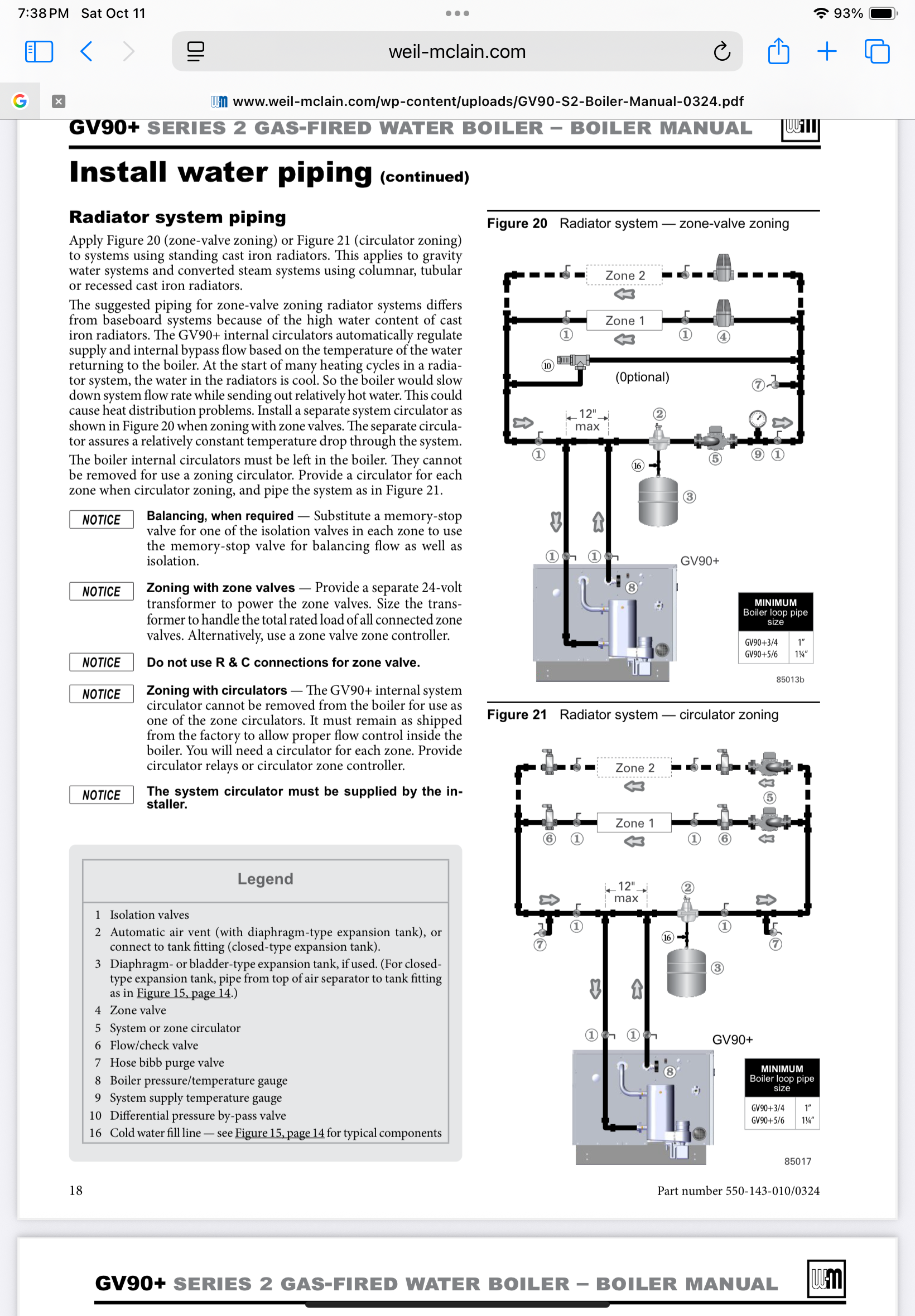
Here are two options they show with zone valves or zone pumps. I think the indirect could be one of the zones?
If you are zoning with valves a deltaP circ would eliminate the PAV #10
 Bob "hot rod" Rohr
trainer for Caleffi NA
Living the hydronic dream0 -
thanks hot rod.
I got all those piping schematics as well. I didnt want to cut into the secondary because it's all insulated, and nice, was hoping to just use the primary piping to add a way to feed DHW. WM said that the 3 way for a single boiler was not allowed either.
Tom
Montpelier Vt0


Categories
- All Categories
- 87.6K THE MAIN WALL
- 3.3K A-C, Heat Pumps & Refrigeration
- 59 Biomass
- 429 Carbon Monoxide Awareness
- 124 Chimneys & Flues
- 2.2K Domestic Hot Water
- 5.9K Gas Heating
- 119 Geothermal
- 168 Indoor-Air Quality
- 3.8K Oil Heating
- 78 Pipe Deterioration
- 1K Plumbing
- 6.6K Radiant Heating
- 394 Solar
- 15.9K Strictly Steam
- 3.5K Thermostats and Controls
- 56 Water Quality
- 50 Industry Classes
- 50 Job Opportunities
- 18 Recall Announcements