Help setting up variable speed injection mixing

I had an earlier thread about hooking radiant up to a Buderus cast iron boiler. I want to thank all that contributed the wealth of information and options. I knew exactly zero about boilers or hydronics a few weeks ago and have come along way.
I figured I would start a new thread since I've picked a direction and got started building the system.
After weighing all options and comparing costs vs functionality and efficiency I decided that the variable speed injection mixing would be the best way to go, and I think I ended up pulling it off for well within my budget range. I sort of combined several ideas together and some of my own.
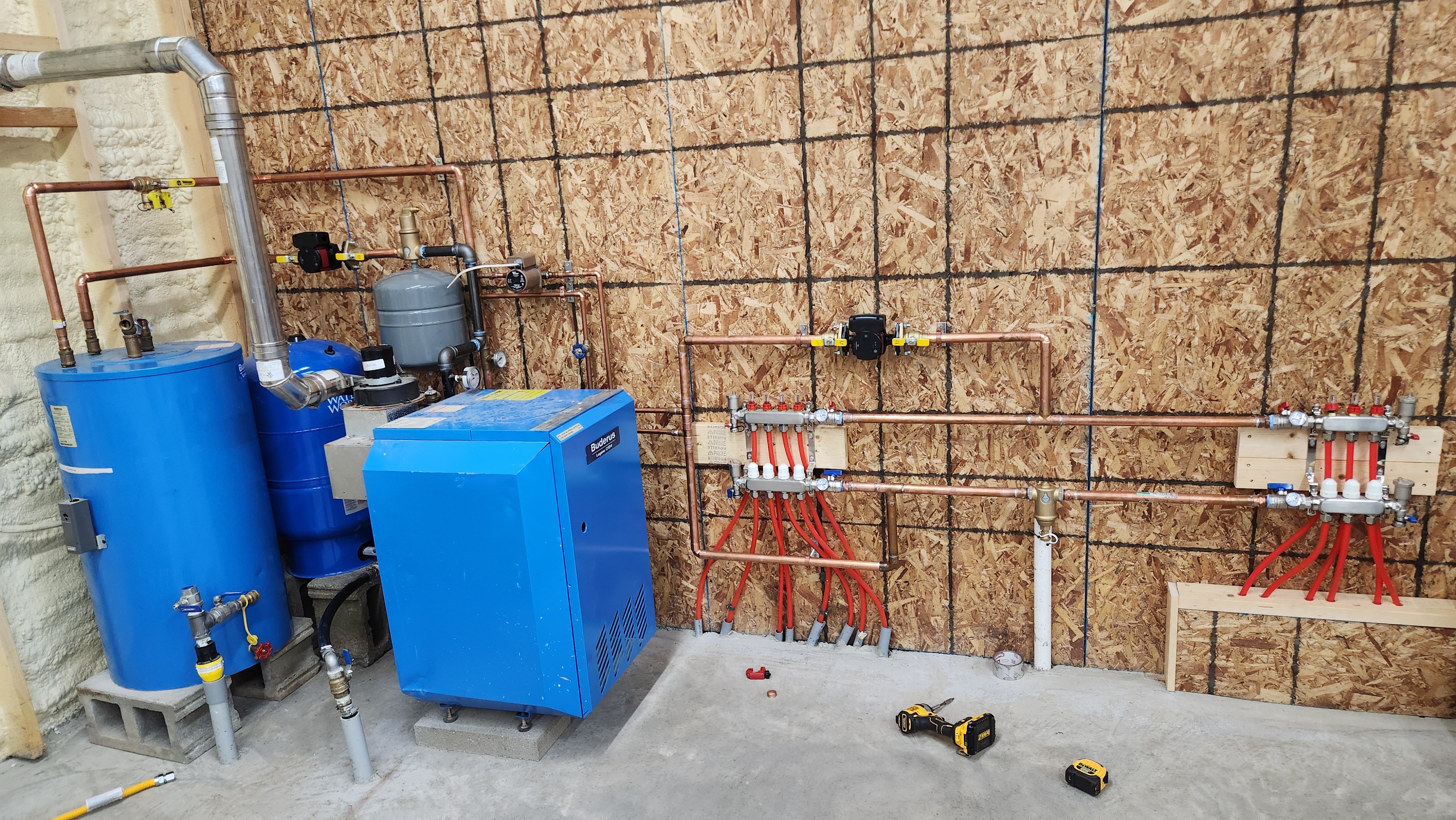
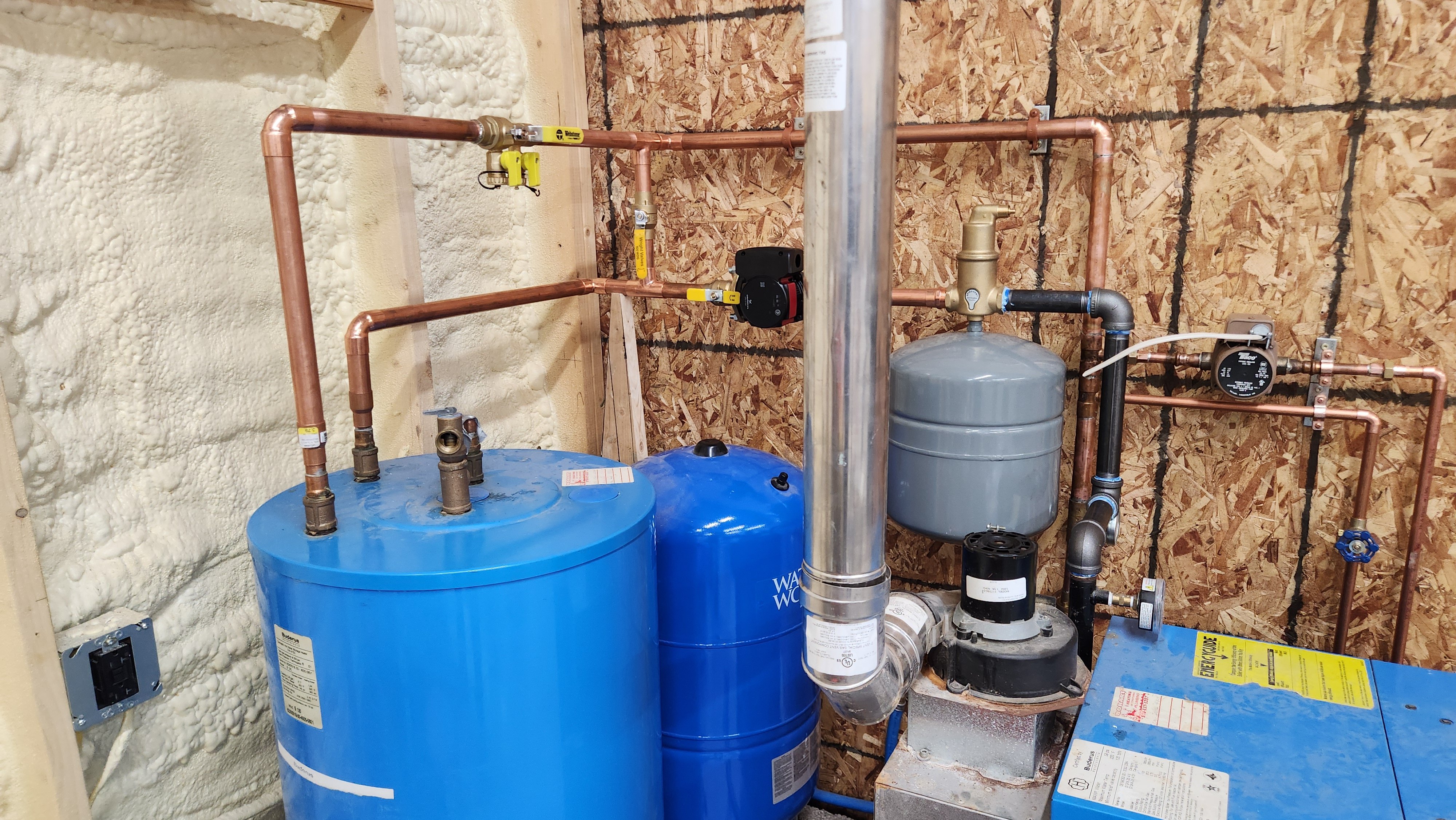
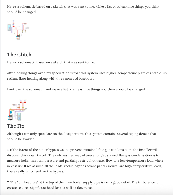
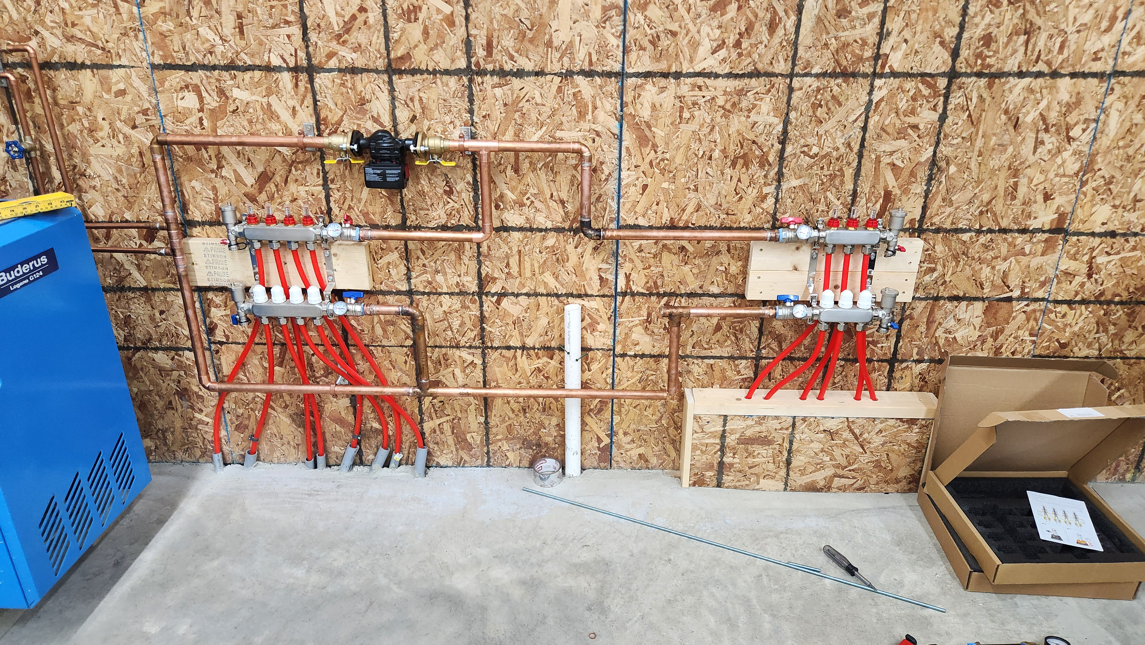
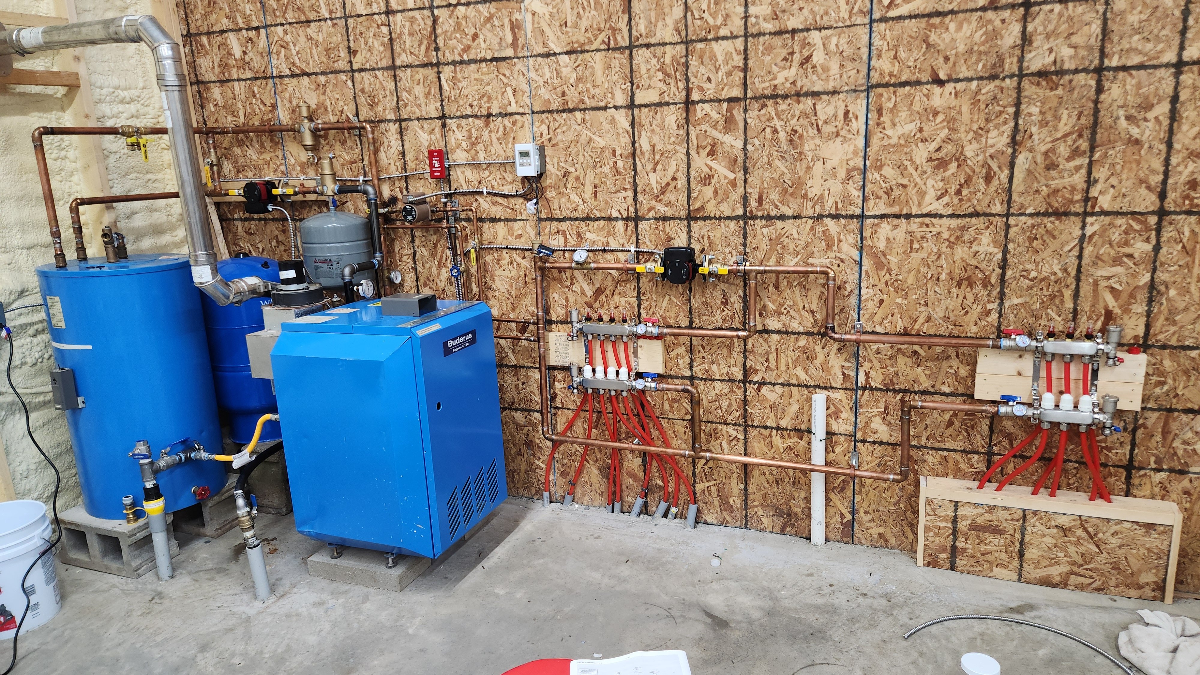
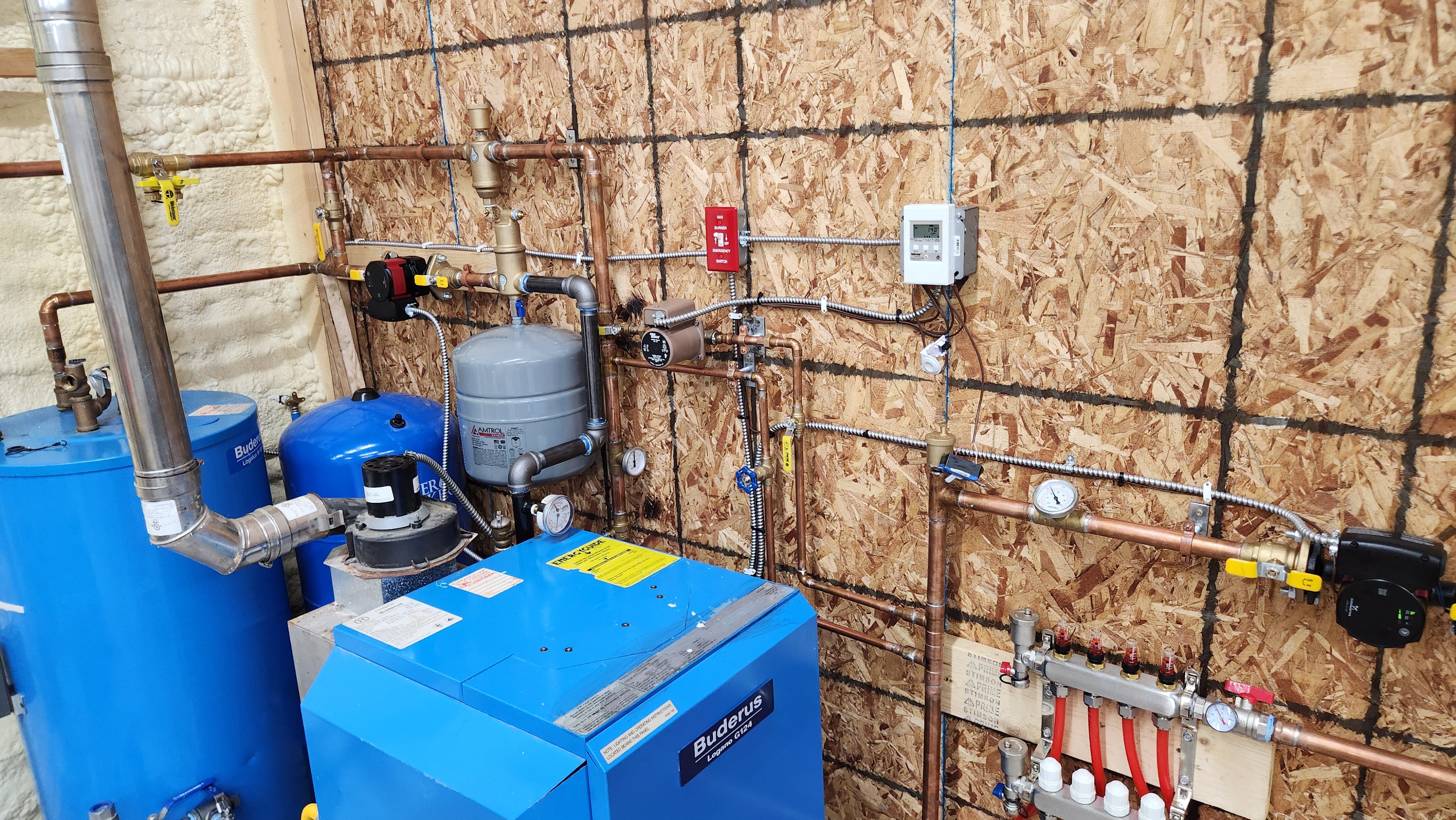
Here are some pictures of where I'm at. I've only soldered the structural parts to be able to dry fit everything together so at this point so it could be reconfigured a bit if anything looks way off.
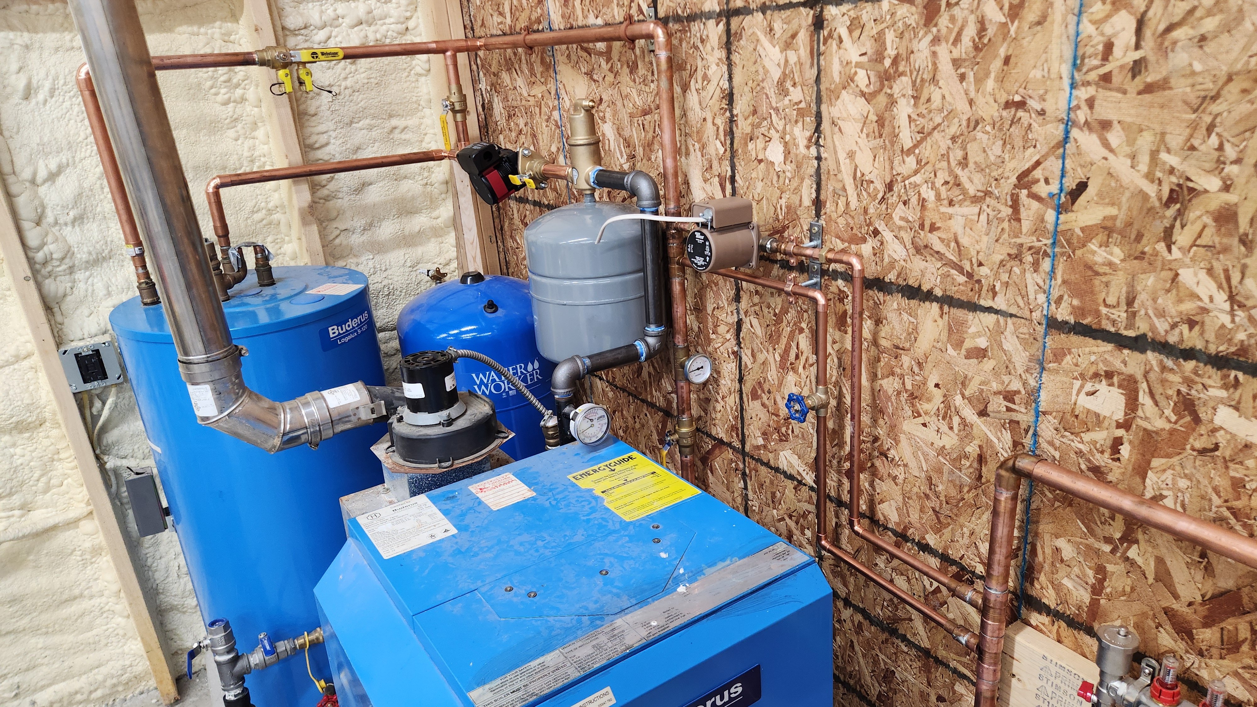
I have the indirect in the primary loop to act as a buffer, and also put in a bypass that I can either completely bypass it or mix incase there is not enough flow through the indirect.
Both the shop and living area are on one zone and I figure I can just throttle with ball valves to see how things go for now.
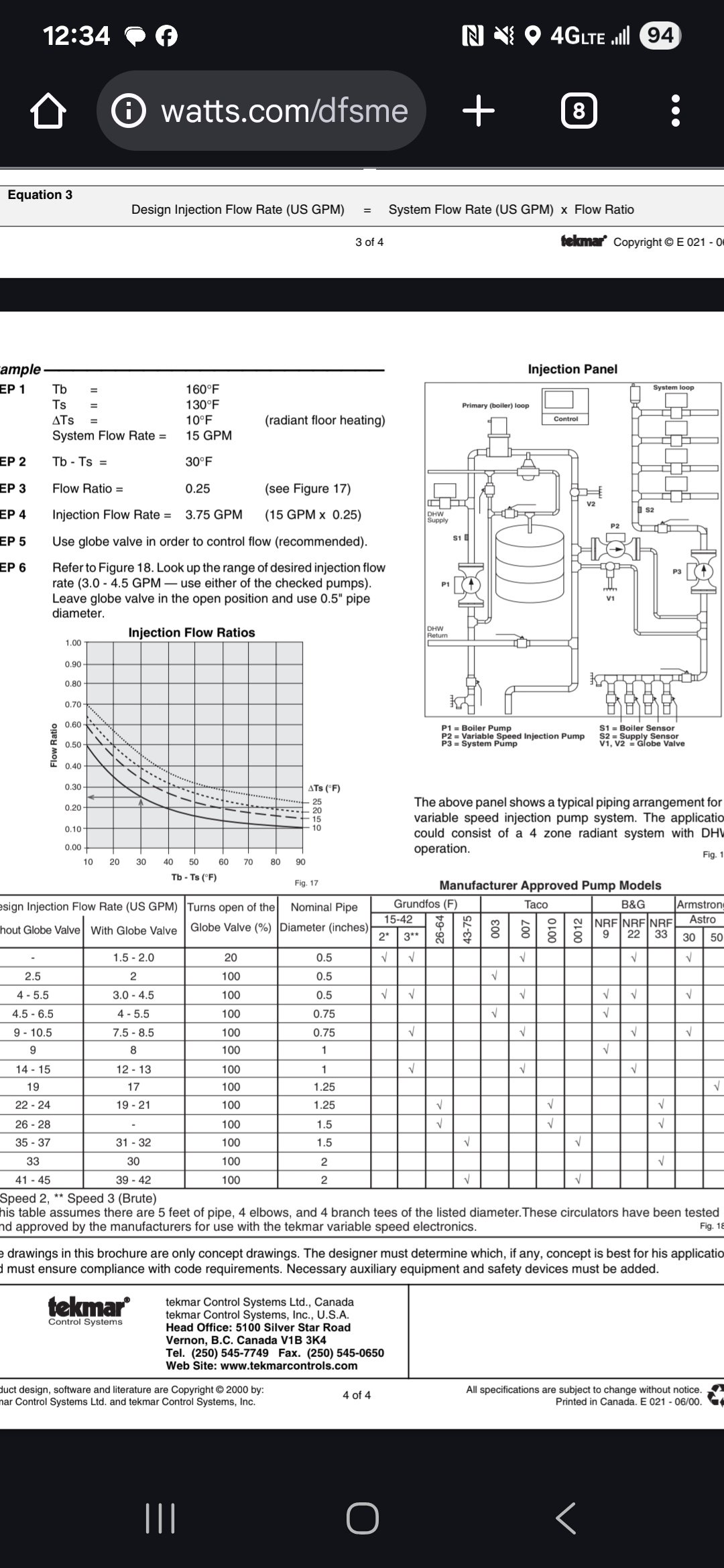
My biggest question this point is about the injection pump. Tekmar has a table of specific pumps and how to set the required flow rate with globe valve position. @hot_rod brought up the issue of finding a small enough pump that could operate at a low flow rate. I found this Taco 006 pump locally for cheap which I think should work if I can get things tuned correctly. It's not in Tekmars table. How do I go about that?
Comments
-
I would use the settings for a 007 and you’ll be close enough, unless you can dial it in with a flow meter.
You should use isolation valves on the injection circ.
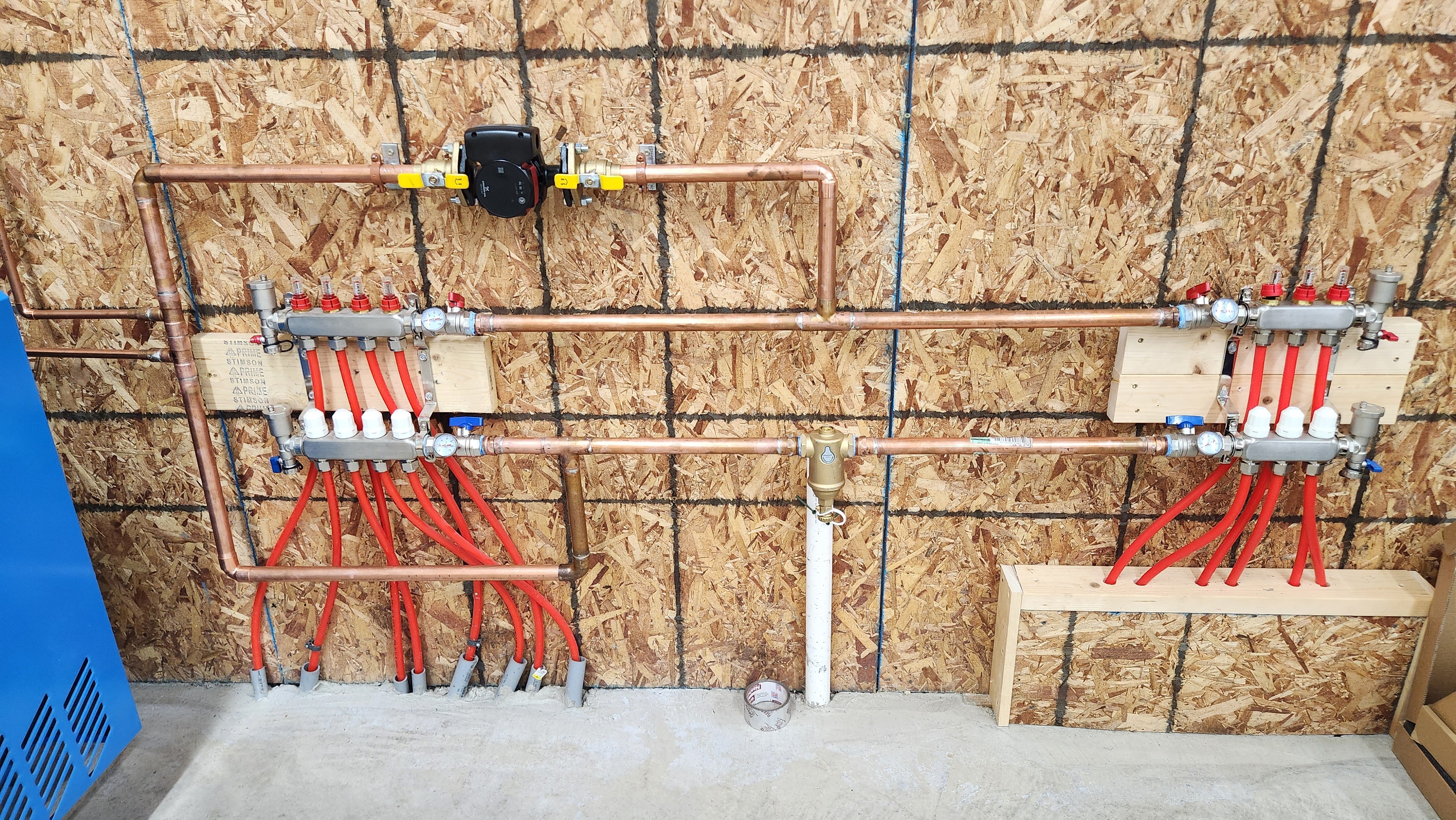
Whatever you have between the two manifolds is wrong. It’s only going to see flow from one manifold.
How are you controlling the injection circ? With the right control you’ll be able to monitor the performance of the injection circ. IOW if you see it ramp up high and stop, quickly short cycling your flow/speed is too high. If your circ is running full speed, and your temp sensor shows temperature dropping, not enough flow/speed.0 -
I have ordered a Tekmar 356 for the injection controller should have it tomorrow.
Will add some isolation valves around the injection pump.
I wasn't entirely sure on the manifold piping. My thought was I could use the ball valves on the manifolds to balance the flow between the two. Would that not work? In the middle of the bottome pipe is a dirt separator, the picture may look like it's connected to the PVC drain pipe behind it but it's not.
0 -
You don't need the separator in that location, and it's only seeing return water from one manifold. You'd want it in the boiler loop after the water feed.
You want to balance the flow on the injection loop circ to account for total btu's needed in both manifolds. You really want enough flow/heat transfer to keep up with the manifold requirements on design day. The control pretty much will come on/off/ramp up and down, based on the connected temperature sensor strapped to the pipe.
You use the valves on each manifold loop to balance the flow/btu's for each loop.0 -
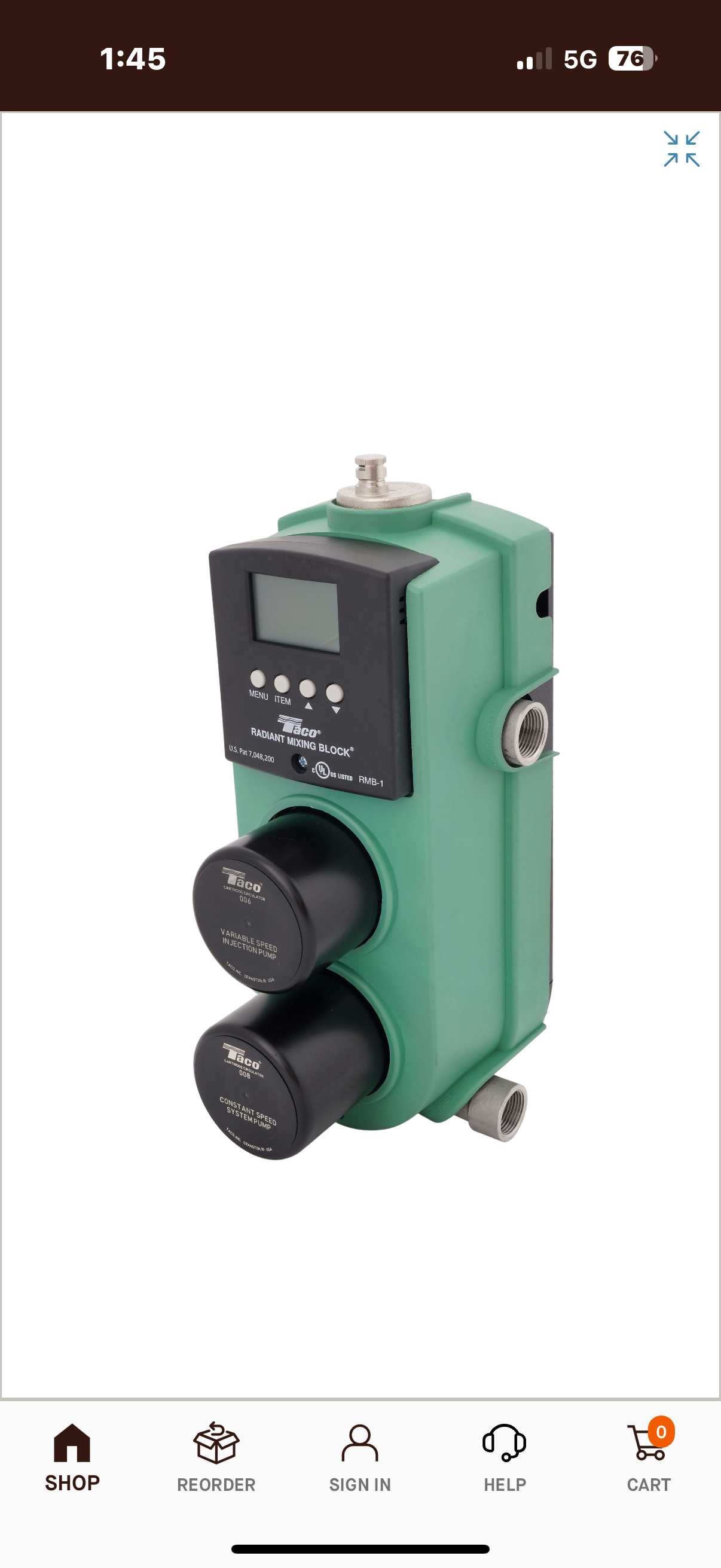
It may be too late, but I’m impressed with the Taco Radiant Mixing Block for injection mixing. Expensive, but so easy to pipe and program.
 8.33 lbs./gal. x 60 min./hr. x 20°ΔT = 10,000 BTU's/hour
Two btu per sq ft for degree difference for a slab 1
1 -
you will need to run the boiler/Indirect circ for the injection to work.
when the tank is hot and boiler turned off you will be circulating hot water through an unfired boiler aka a cooling tower
It’s not a very fuel efficient operating condition
You need to do some math to properly set up the injection flow rate The boiler operating temperature, injection temperature determines injection flow rate
I doubt you will maintain the indirect at 180? But you need at least 130 return to the boiler, so 150- 160?
You will need a thermostatic valve on the dhw if the tank is maintained that hot
Bob "hot rod" Rohr
trainer for Caleffi NA
Living the hydronic dream0 -
Ok I guess there are some things I'm still not quite understanding with the injection. So you're saying the circulator on the boiler loop needs to be running full time even when there is no call for heat? If there was a call for heat but the boiler wasn't firing wouldn't the heat from the tank just go into the floor?
0 -
The boiler can be run either way. Generally a cold start saves fuel but can cause condensation issues with some setups. Since you have the injection setup, this should not be an issue.
Your thermoset goes to the Tekmar, the Tkemar TT wires to your boiler. If there is call for heat, the boiler is turned on and it will run till it hits is upper limit. If things are set up properly, it won't cycle too much off the upper limit.
If I remember correctly, your boiler is 80k and your floor heat is 40k, that means you want the primary pump at 8gpm and the floor heat pump about the same (20f delta on boiler, 10F delta on floor heat). Without a flow meter, the mix set will have to be a guess. Maybe start with fully open and slowly close it if temperature control on the injection loop is not good.
I would add an air bleeder on the high point of both loops. Can be just a T with small valve/auto vent or one of the cheap air seps. This will significantly simplify getting the air out of the system especially the floor heat loop.
The dirtmag would have been better on the boiler loop as that will be the source of steel. It can work where you put it as well if you are worried about dirt in the floor heat loop, but I would move it on the return to the pump so both loops flow through it.
0 -
Lots of helpful information thank you Kaos.
Do you think the manifold piping could work as is for both on one zone or is there a better way?
If I don't have problems with short cycling my plan would be to eventually zone them separately but for now we'll see how things run.
0 -
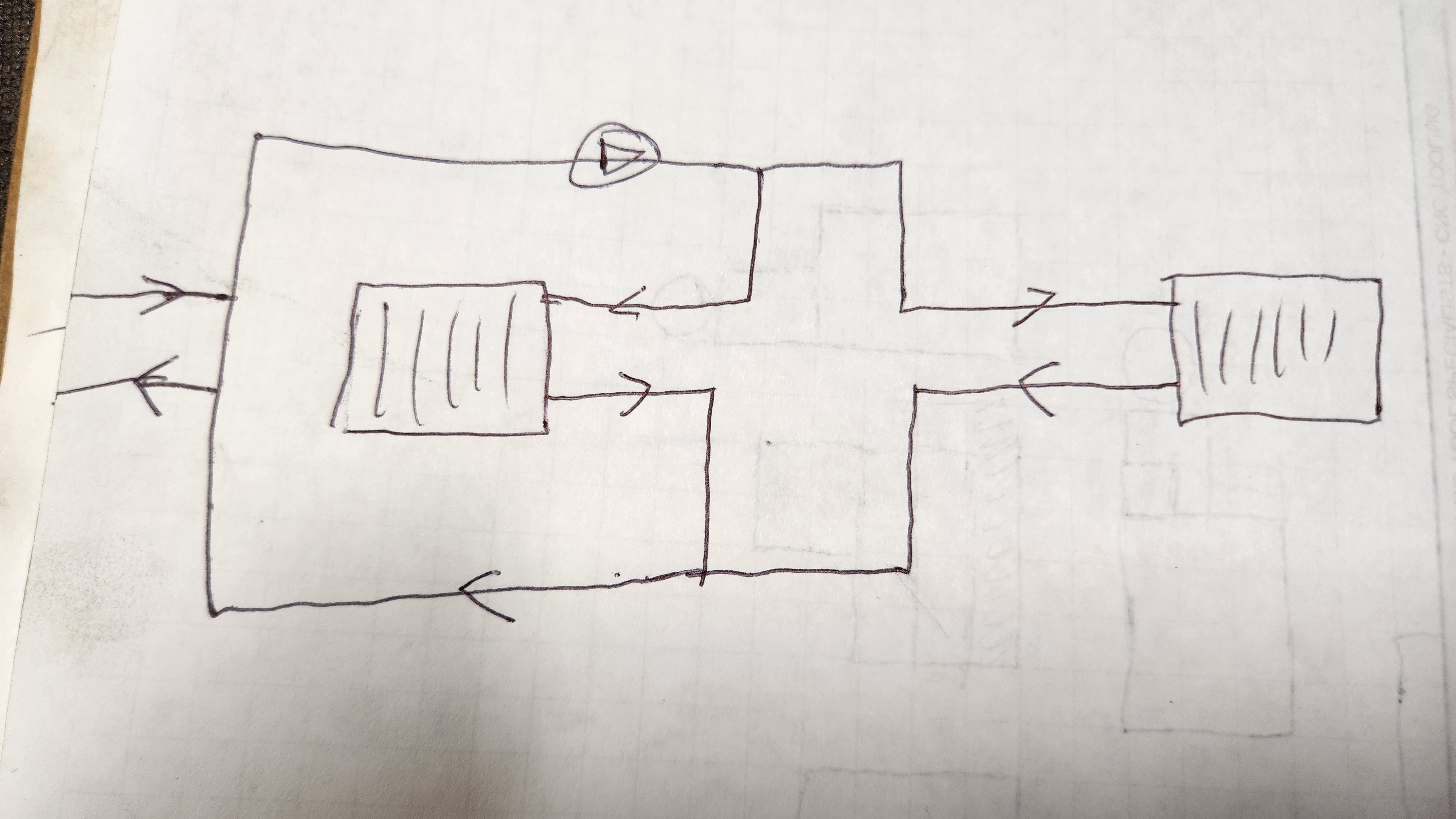
As I see it you have the boiler piped in series with the indirect, correct?
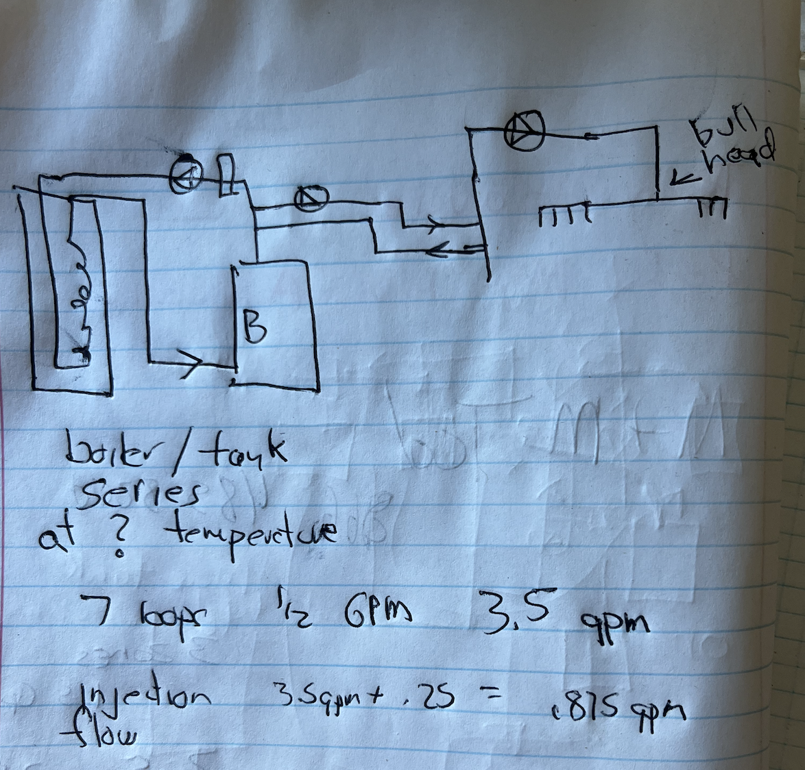
So that tank needs to be maintained at a temperature to provide the injection mix.
Use the tekmar example showing the boiler running 130/ 160°
So the tank will reach @ 160°, correct. Protect the DHW from leaving the tank at those temperatures!
Now on a call for heat the boiler pump needs to run, as it supplies the needed temperature across the close tees for injection. There may be times that boiler pump is running but the boiler is off, as the tank is hot enough to supply heat. So some of the tanks heat at maybe 160° is going through the boiler.
The radiant pump also needs to run, so 3 pumps need to be running to get heat.
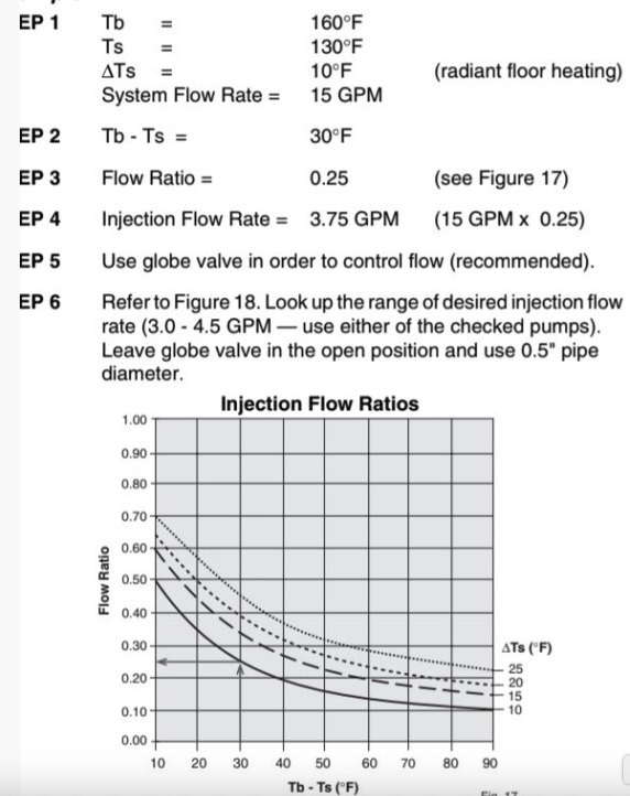
I see 7 loops of 1/2" pex. Typically we design for 1/2 gpm per loop, so you have a 3.5 gpm required flow with all loops connected. If you close off or zone off 4 loops the gpm requirement is 1.5 gpm. (short cycling will get worse not better if you zone the system)
Plug those numbers into the tekmar formula, looks like a .875 gpm injection flow required.
This example is for a system with 15 gpm system flow, I think you are around 3-4 gpm?
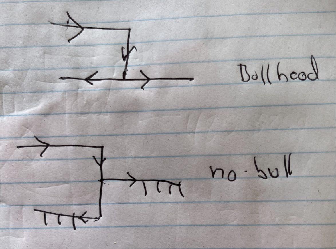
If you have not soldered yet, get rid of the bull head tee on the manifold piping.
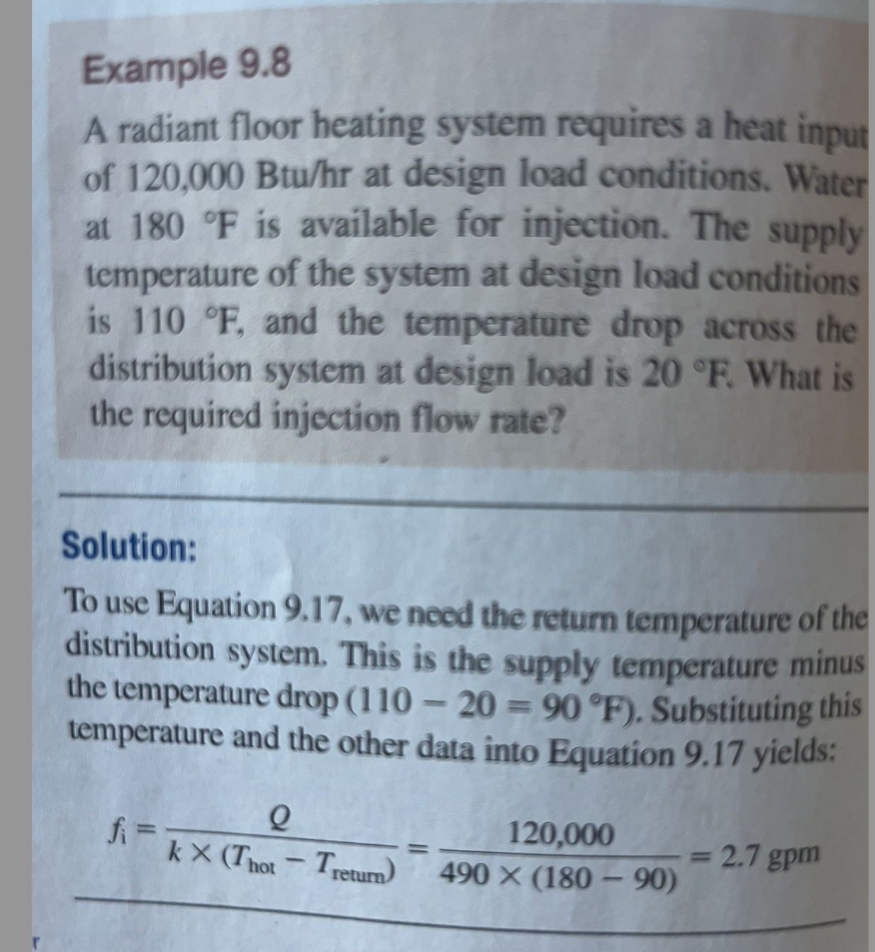
This injection formula, from Modern Hydronic Heating is a bit more precise
you have a 40,000 load, boiler at 160? supply radiant at 110, return at 100° (10°∆)
40,000÷ 490 (160-100) 1.3 gpm
Without a load calc and design I'm guessing at the load and required SWT to the radiant
 Bob "hot rod" Rohr
trainer for Caleffi NA
Living the hydronic dream0 -
Great information.
Yes the boiler is piped in series with the indirect just as your sketch. There is also a bypass to either bypass the indirect entirely or do a mix. I figure I could use the same piping to zone the indirect off with a circ in the future if there's a need.
As far as getting rid of the bullhead tee in the manifold piping, what do I put in place of that?
I will for sure put a tempering valve on the indirect when that gets plumbed into the dhw. No need for hot water for a while until we have septic next year.
0 -
plenty of discussions over the years regarding bullhead tee installation, some steam some hydronic. ME a former hydronics instructor explained it well here.
Caution..... Educational Rant ahead....
Bill, One of John Siegenthalers very first articles had to do with the use of bull head tees in a closed loop circuit.
It causes hydraulic imbalance because the direction of flow, and subsequent pressure drop, which affects flow continually changes. Not good.
Lets say you have 10 GPM going into a bull head tee, with each branch of the tee requiring 5 GPM. As the water starts flowing initial, it seeks the path of least resistance. As more water starts flowing through branch A, the pressure drop in branch B becomes less, and it becomes MORE in branch A, so the flow slows in branch A and increases in branch B, until it's pressure drop increases, then it starts all over again.
Remember, water is wet lazy and stupid, and has a really hard time making up its liquid mind. If you had balance cocks on each branch, you MIGHT be able to somewhat stabilize the flow, but it would be tricky. The code use to disallow the use of bull head tees in hydronic systems, but due to inspector confusion over primary secondary piping, and pumped priority, they abandoned that clause of the code completely 2 code changes ago.
The ideal way is to split flow to two branches by drawing from the run and the bull. This way, the hydraulics "lock in" and flow remains stable, until interrupted by a zone control device. I've actually felt the back and forth surging associated with bull head tees using the OHHhhh AHHHhhh method. If you had flow meters in each branch you'd be able to physically see it.
 Bob "hot rod" Rohr
trainer for Caleffi NA
Living the hydronic dream0 -
Got it. Makes sense now. I guess I was piping with the thought process of an electrical circuit which is more up my alley.
Is it ok for the manifolds returns to both be running into the runs on the tee or should I try to configure that similarly? Sort of a reverse bullhead if that's a thing...
0 -
Maybe like this?
 0
0 -
There are places where a bullheaded tee piping cannot be avoided, like the injection mixing tees. But to avoid them when possible on other piping.
 Bob "hot rod" Rohr
trainer for Caleffi NA
Living the hydronic dream0 -
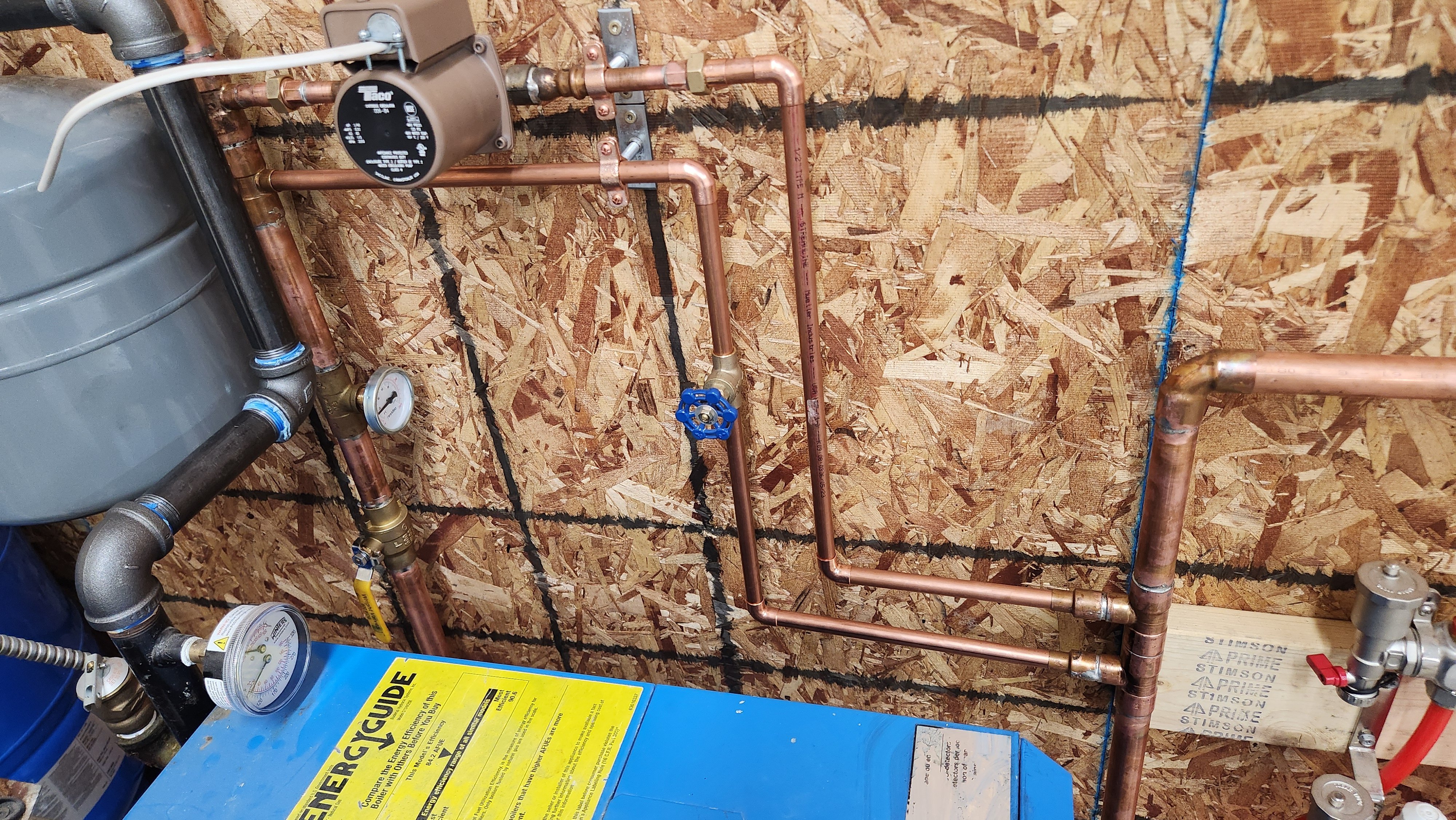
Ok I did some rearranging to get rid of the bullheads and relocated the dirt separator to the boiler loop and have that side all soldered up. Need to pickup a couple more elbows, I plan to finish the plumbing and soldering on the system side tonight and pressure test. I have some automatic air vents to put at the high points.
What can I use to flush out the system from flux and and other junk before filling with glycol? It looked like the boiler itself could also use a cleaning there was some bright orange/brownish looking mud in the return when I pulled off the old pipe that was on it.
 0
0 -
Looks much better. I would still put something like a Taco airscoop right before the floor heat pump to allow for simple bleeding of the setup. The floor heat pump should also not point down, you want the motor shaft always to be horizontal.
0 -
Oh yeah thats just a dry fit the circulator turned down on me when I was rearranging the pipes, shaft will be horizontal when it gets soldered.
My plan was to put a tee where the elbow is before the floor pump with one run pointing vertically with an auto air vent on it. Would that work or do I need the scoop?
0 -
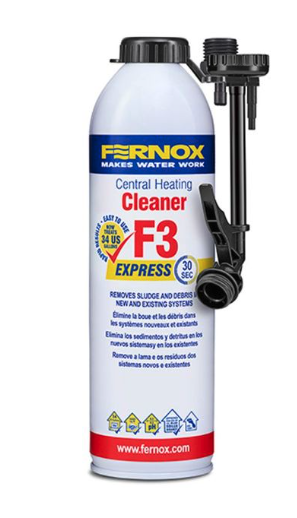
Yes you want to get all the flux and oils out of the system or it will compromise the glycol.
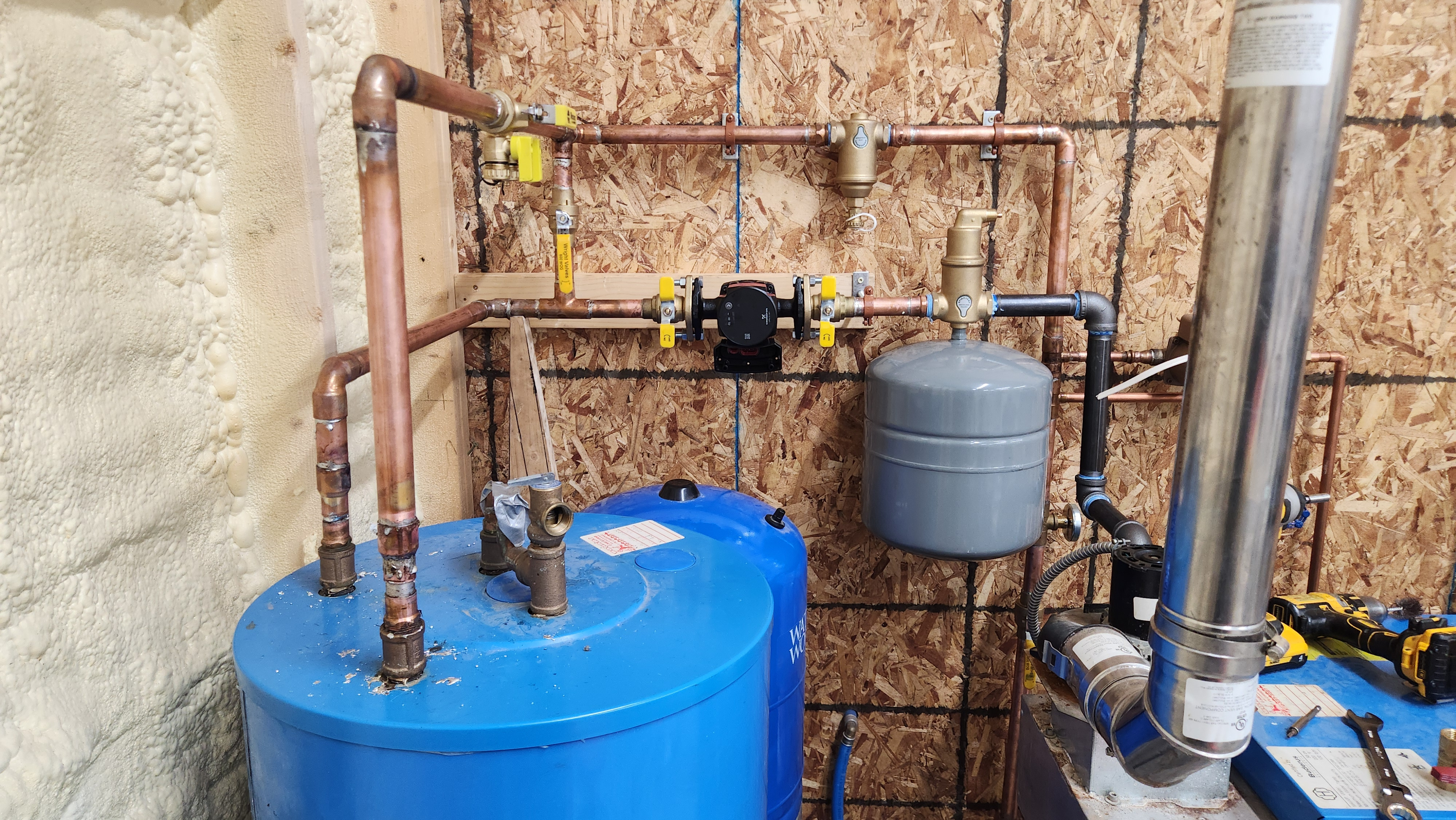
Rhomar, Axiom, Fernox all sell these easy to use cleaners. Screw tightly onto a hose connection and pull the trigger. Run the system to temperature so the cleaner works well. Flush completely before adding glycol.
Pressure test with water before you add the cleaner, in the rare unlikely case you have a leak :)
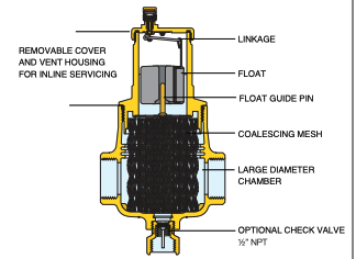
Caleffi air and dirt seps use a composite screen to deal with glycols best. Very easy to disassemble and service.
 Bob "hot rod" Rohr
trainer for Caleffi NA
Living the hydronic dream0 -
Sounds good I'll see if I can find one of these cleaners.
I had planned to pressure test with air in the event that there was a leak and would be much easier to fix that way. Is there any harm in doing that? Honestly I'd be shocked if there wasn't a leak 🤣
I already did the manifolds independently before running any copper and they held 15psi over several days with no drop.
0 -
Air is a good first step. I have seen systems hold air, then water and cleaner flushes out the flux and leaks appear.
Air test, fill run cleaner, if leaks appear deal with them then, maybe.
Unless you isolate the boiler you are limited to about a 25 psi pressure test, due to the relief valve.
Bob "hot rod" Rohr
trainer for Caleffi NA
Living the hydronic dream0 -
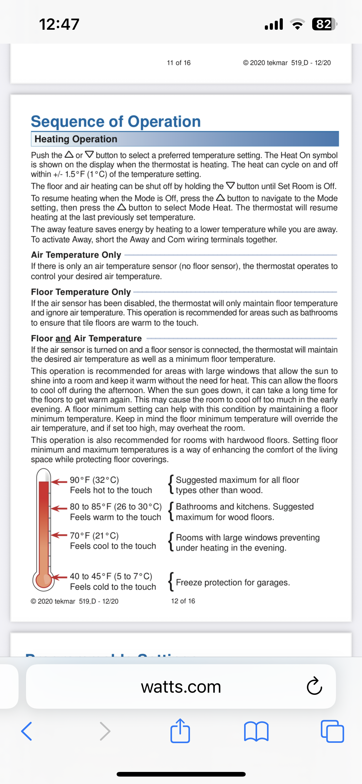
I haven't purchased a thermostat yet, from what I gather with the slow response of a radiant slab it's basically a "set it and forget it" system rather than trying to program up and down for day/night.
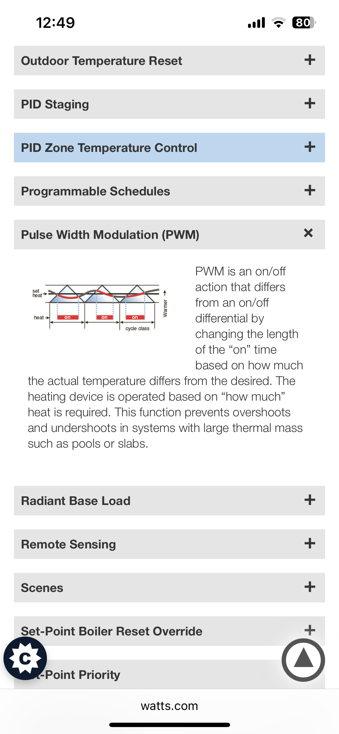
I do see Tekmar has a thermostat with a slab sensor. What would the benefits of this be? And could you accomplish the same thing by just putting a regular thermostat on the floor? Tekmar is touting that it uses pulse width modulation, I understand what PWM is from an electronics standpoint but I don't see how it would even apply to switching a boiler on and off, PWM is usually a very high frequency.
0 -
Slab temp is only needed if you need something like min slab temp for freeze protection or max temp for flooring like hardwood. You don't have either issue, so slab temp won't help.
Any standard thermostat that can be configured for high mass will work. I use a couple of Honeywell th115 that can do either air or air and floor. They are programmable, but I just run them on fix temp.
0 -
the 519 is my favorite stat for slabs, if you don’t want WiFi
The tekmar website has all sorts of info on the how and whys of their controls
Ideally you would have a sensor well poured into the slab to best apply the slab sensor function
The pwm is a good feature for slabs especially if you don’t have ODR capability
It takes the stat beyond a basic on/ off switch
 Bob "hot rod" Rohr
trainer for Caleffi NA
Living the hydronic dream0 -
Ok I have the system up and running. Everything seems to be working perfectly. It's impressive to watch the control ramp the injection pump up and down to maintain temps. It's keeping the return within a few degrees of target temp which I currently have set at 140f. I started with the globe valve on the injection pump fully open and the control shows it working around a 10 to 50% load most of the time.
It's unseasonably warm here, high 70's so not great for testing heat. I haven't mounted the outdoor sensor yet and just have the control set for mix setpoint value for testing. I cranked the mix temp target up to 120 just to see the system work. I don't have any water in the indirect/buffer tank and have it set to bypass so it's not in the loop. I only had time to run for about an hour before it was bed time and the boiler never shut down in that period and my mix temp had gotten up around 115.
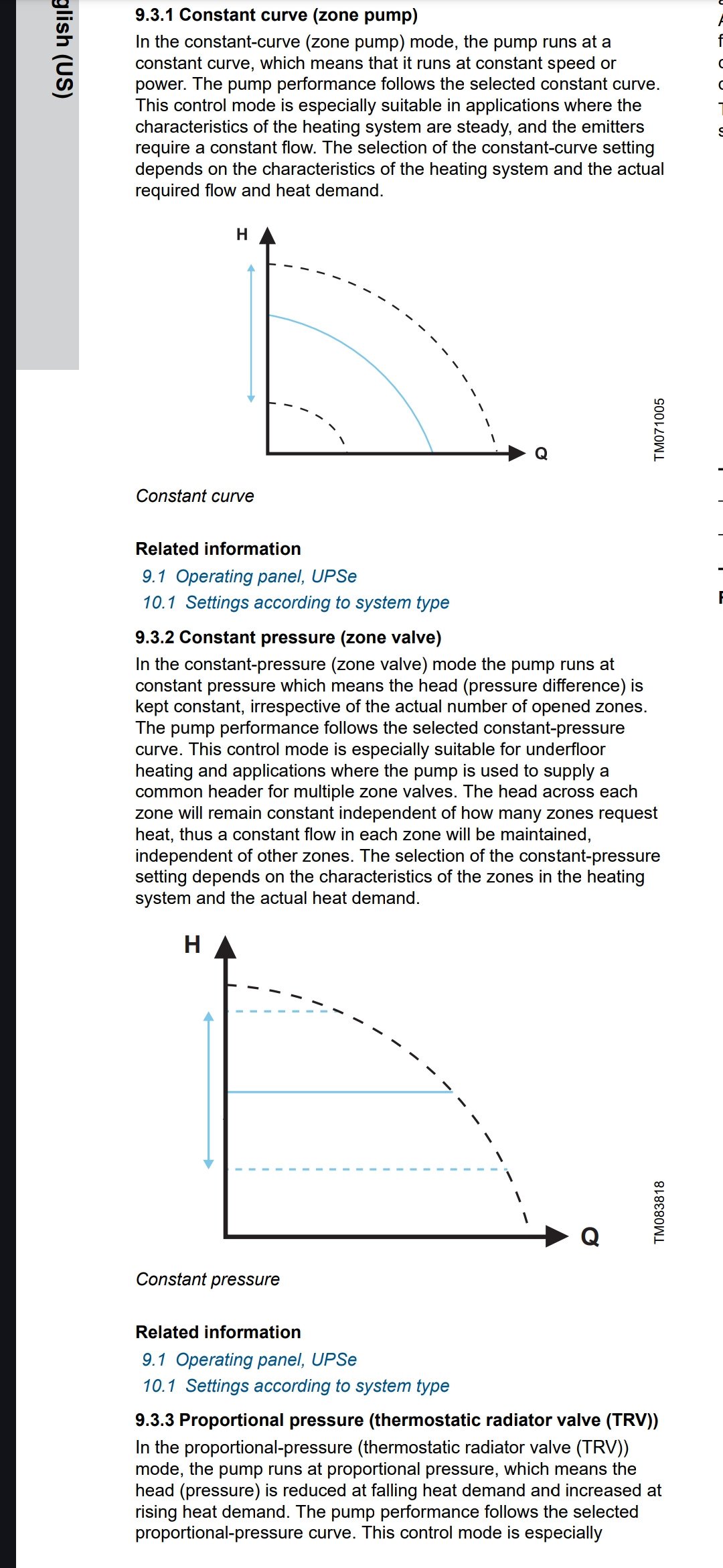
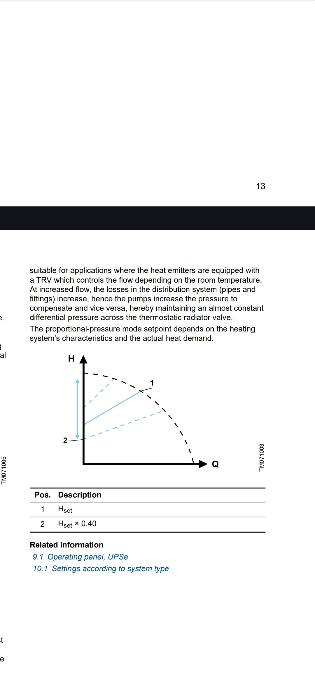
I have the Grundfos 3 speed ECM pumps on both primary and secondary. They have 3 modes, constant curve, constant pressure and proportional pressure.
Which mode would be best for my application and how do I know what speed to use?
 0
0 -
With ECM circulators and the tekmar controller you might get a power conditioner, UPS, to protect all the microprocessors
Bob "hot rod" Rohr
trainer for Caleffi NA
Living the hydronic dream0 -
Good job getting it all setup and running, nice clean install.
General rule of thumb is you want to pump as little water as needed. On the boiler loop run the Alpha in fixed speed. Adjust the speed to get about a 20deg delta across the boiler when firing in steady state. More flow (lower delta T) doesn't hurt, less can create issues.
On the floor heat site, set the pump to delta P mode. Open all the loop adjusters, turn on the pump and adjust the delta P setpoint until you have above design flow on all your loops. From there, adjust each loop to get the design flow, don't adjust the pump setting.
This way when you do zone in the future, the pump will then automatically adjust to keep design flow rate through the loops regardless of which zones are calling for heat.
0 -
I think I got things setup pretty well, just have to wait for the weather to drop to see how it runs.
Thanks to everyone for all the help.
I have one last area of concern. I was looking up into the draft hood and saw it was significantly corroded and the flue damper under the draft inducer was siezed in place about halfway open. I reached my arm up in there to try to move the damper and I could smell the flue gas and it had a strong sour smell that clinged to my clothes all night. Is this normal? Maybe why the draft hood was so corroded?
I don't smell anything while it's running, just when I was up close in the draft hood right after shutting it down.
My brother gave me a some spare parts woth the boiler, one being a brand new draft hood that has the swinging damper built in so I will get that changed out tonight.
I have two CO monitors in the shop and neither of them have went off.
Just wondering if the smell is normal or not and what a sour smell might indicate.
0 -
Update:
After some research I see that methyl mercaptan is added to natural gas as an odor identifier as natural gas is otherwise orderless, and that the burning of methyl mercaptan produces sulfur dioxide which has a pungent odor of burnt matches. I would say that pretty closely resembles the odor I smelled. So it should be normal?
0


Categories
- All Categories
- 87.6K THE MAIN WALL
- 3.3K A-C, Heat Pumps & Refrigeration
- 59 Biomass
- 429 Carbon Monoxide Awareness
- 124 Chimneys & Flues
- 2.2K Domestic Hot Water
- 5.9K Gas Heating
- 119 Geothermal
- 168 Indoor-Air Quality
- 3.8K Oil Heating
- 78 Pipe Deterioration
- 1K Plumbing
- 6.6K Radiant Heating
- 394 Solar
- 16K Strictly Steam
- 3.5K Thermostats and Controls
- 56 Water Quality
- 51 Industry Classes
- 50 Job Opportunities
- 18 Recall Announcements