Water to Water Geothermal heat pump replacement with lp boiler
Comments
-
The wells were checked the flow is way below the MFG spec. The pump you have will only pump the flow you need if the head does not exceed 24'
How many more opinions are needed?
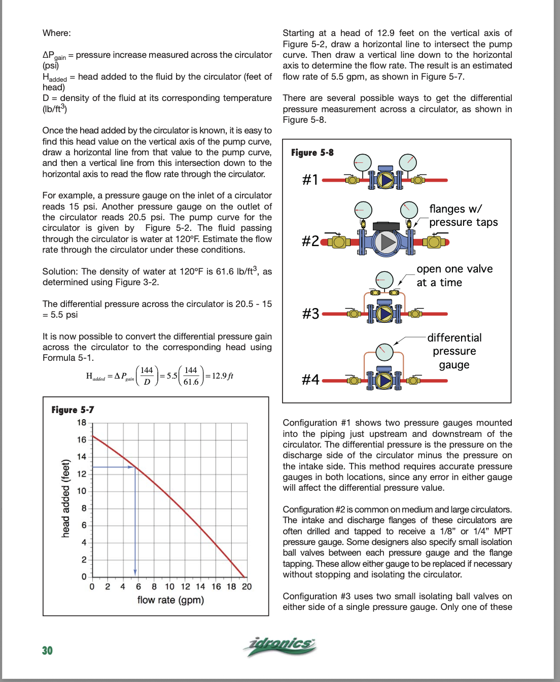
Put pressure gauges across the pump and convert them to ft of head this will give you and approximation of the system resistance.
Looks to me like your way under pumped and need a larger circulator but pressure gauges will tell you the system resistance or at least an approximation of it.
0 -
Depending on how far you want to go with data collecting and number crunching?
Here is the math for calculating system flow, from Idronics 16. You need a pressure gauge and a means to connect it on both sides of the pump. I prefer method #3 so gauge error is eliminated between two gauges.
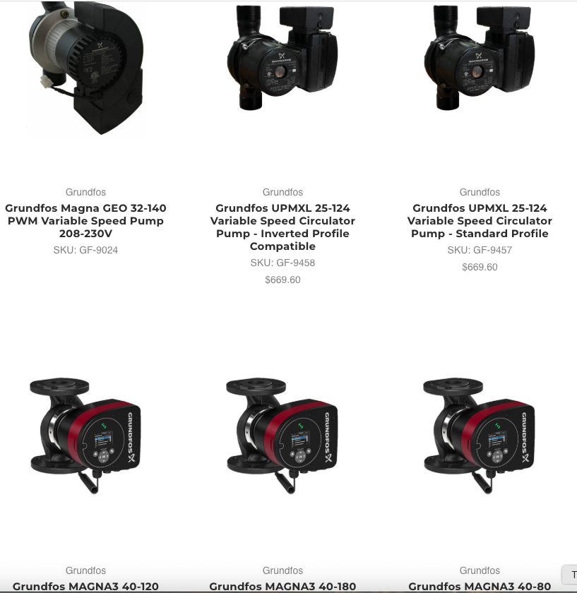
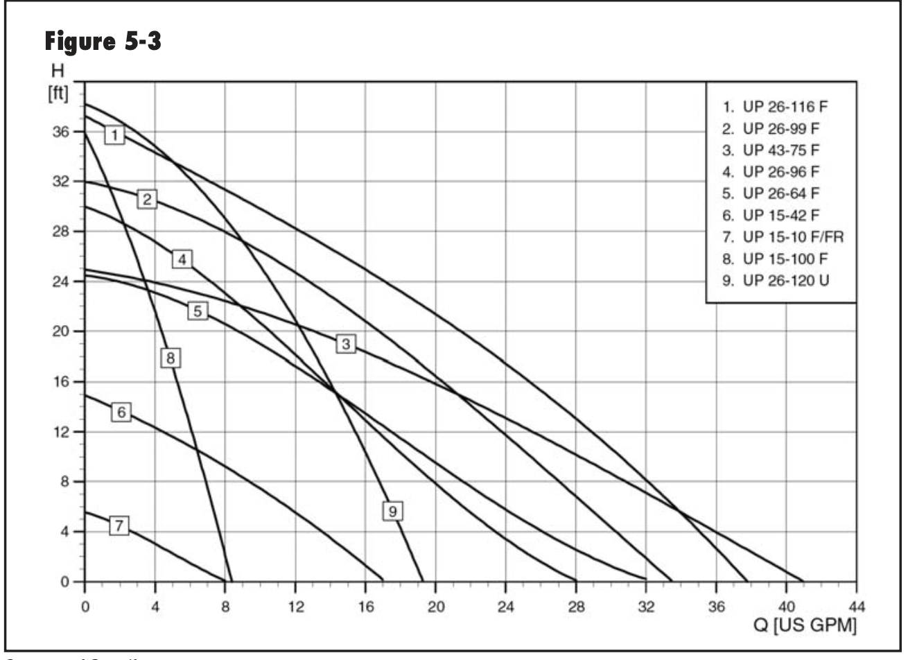
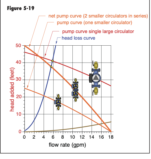
Attached a pump graph showing various Grundfos pumps. You can series pumps, this is often done in GEO pump stations to keep costs down.
If you need more flow I would series another pump to the one you have. Two Grundfos 26-116 in series, Fig 5-19 below, get you 16 gpm at 50' head. Use pump curve #1 on the chart showing all the pumps
Or if you want a low power consumption an ECM geo pump, like the Grundfos Magnas, is an option. But they don't come cheap.
 Bob "hot rod" Rohr
trainer for Caleffi NA
Living the hydronic dream0 -
And keep in mind the measured GPM will be the current conditions and not the theoretical. If the service guy was able to get all the crud out then they would both be close, which is a good sign that builds confidence. It's good to get confidence with the theoretical model and the measured valve. It just seems pretty wild to me a geo contractor would install the field system without knowing the load to service and the pump calculations to make that happen, which is why when I saw your comment about 55ft of head and seeing that number came from the default selection of pipe material in the drop down menus, it made a flag go up. It's important to get the material selection right in the model as a "3/4" nominal schedule 40 vs copper pipe selection have different inner diameters and roughness. This is actually one of my biggest gripes in the plumbing industry. Sorry if all this is Capitan Obvious but want to get to basics.
If you determine you need two pumps and you are confident in the model and measured values, you can potentially then optimize for price. Some of these beefy high head pumps are costly and pull some serious watts. Let's say you wind up needing 35ft or 40ish, that might put you in the realm of using 2x smaller Grundfos UP series pumps which are decently less money; then sell the 26-116. Or maybe 2x ECM pumps will work technically and economically. The good news is you are getting close to confidence on the ground loop side and we will guide you once you confirm the model and actual measured values.
I also agree the piping on the load side looks odd in the pictures. How many thermostats do you have in the house and what kind of radiators do you have? The poor mans solution might be to turn every zone valve on and off based on a single thermostat if that is comfortable enough. This might require some "operational" family changes like keeps some doors open to avoid small room overheating. It's really tough for me to the design of the loads from the pictures. Post some more zoomed out in high resolution from multiple angles with some notes.
0 -
We have 5 zones with thermostats. 2 are imbedded in 4" concrete and 3 are imbedded in 1 1/2" gypcrete. Each zone has its own circulator on the supply side. The heat pump circulator is on the return side right before entering the heat pump.
0 -
Small zone loads are probably the main issue now that the source loop is cleaned up a bit. So all radiant heated floors it sounds. I glanced at the heat pump specs. Manufacturer says it will run with like 5 gpm on the source loop side but for “open loop” applications where the heat source is much more constant, like a lake. In closed loop application in dirt and stone you are essentially chilling the ground and the return source temps might trend colder as you extract heat from the soil due to higher thermal resistance of the surrounding soils. A lake would stay at a much more stable temperature. When the unit is off it takes time to conduct heat back around the wells in soil, so the manufacturer says to pump more gpm’s to harvest more heat when the ground cools and the loop temps decrease. With cooler temps you need to pump more to extract heat from cooler temps.
You addressed the source loop fluid contamination so that is a step forward and was needed.
I would still confirm the loop side design and total pressure drop. How far is the equipment room from the geo field? Is there a hatch on a manifold section where you can find a factory marking on the piping used for the well loops to refine the loop pressure drop model? Or can you share all docs you have from the installer?
You said you are short cycling and have a bunch of zones. At 30F source fluid temps you are still transferring like 25 to 35kbtu/hr, total, based on the heat pump data sheets- more btus/hr with warmer soil temps. That is a decent amount and probably overpowering at least one zone- so not surprised you notice rapid on/off cycles.
Do you think you can accept combining some zones together? Honestly it might improve comfort depending on your home layout and solar gain / lack of solar gain. This would be a low cost solution.If you want to keep all current zones, I suspect you need a buffer tank as others said. We need more information on your zone square footage, and sun exposure. You could trim each zone with manifold or valve adjustments. The down side is you have a bunch of pumps running. The optimal way is to have one constant pressure ECM pump feeding all the zone valves for each zone. Five pumps is unnecessary. Maybe not a be big deal if kWh’s are cheap for you. In Cali it adds up.
How do you heat your hot water?
0 -
I currently have an electric water heater with desuperheater on the heat pump with circulator tied to it
0 -
Can you further isolate the three wells and flush them with high strength vinegar to break up any more deposits?
Until you flush the wells more and tie all of the zones together to create a single zone and add hot water storage I doubt seriously you will see any improvement.
0 -
Agree with Leonz; but hard to say 100% not being on site. Take a look here:

Confirm the model number above, if wrong the concept of the below still applies:
Ok, for the max heating application given for the EW042 in the spec tables (approx. ~120F given to load circuits), for a given ELT (entering load temperature), if you look at the HE column (heat extracted) for each EST row (entering source temp) and Source flow (5.5, 11, 16.5 gpm), the kbtu/hr increase is minimal / in the noise band. But as EST increases, the kbtu/hr increases significantly.
So, I would take another pressure reading at the heat exchanger to estimate your source flow rate now that you had it flushed. If around 11 gpm, I would call it good. Going to 16.5 gpm just burns pump kWh's for not much / nothing. You can see the note in the image above that water furnace says below 11gpm source flow is only for EST's of 50F and above, usually for a lake loop or something with consistent temperatures. In a ground loop with source temperatures below 50F they want you to have more flow to extract more heat from cooler (<50F) source loop temperatures. Depending on your parcel geology you might be able to get away will lower than 11gpm, but Water furnace says minimum of 11gpm. Keep in mind that as EST increases, the heat extracted (HE) rises quickly, so if you have warm source loop temps, even at 5.5 gpm+, you might be trying to shove a ton of heat into one of your 5 smaller zones.
A buffer tank in a radiant application would be a bummer in my opinion unless its a low "mass" application like staple up that doesn't have a lot of storage capability to increase run times. A buffer tank will help but keep in mind capacity and run times are determined by the cycle beginning temp/energy level and the cycle end temp/energy level of the tank, and not the total tank potential energy storage. The difference is lost on shutdown depending on insulation levels of the tank. Mild weather run time min. target is ~15m, cool min. target ~30m, cold is 30+. These are approximate.
Depending on the layout of your zones, you might increase comfort if you change some of your low voltage thermostat wiring so a strategic thermostat activates a couple of your zones. I would probably try to combine any lower mass (staple up) radiant with higher mass (thin/thick slab) to buffer the low mass zones. With 5 zones I can imagine a situation where the smaller / lower mass zones are fighting one another and interacting negatively; you want a slow reacting and stable control system.
0 -
I did test again after wells were flushed and still getting a 2psi pressure drop and 8 degree delta t. I talked with the guy that flushed the wells and he thinks that the geoflo circulator size, the amount of wells and unit size are not completely compatible and thats why the pressure drop is so low and output has never been as it should of been. He said he is only interested in putting in a new geo unit, buffer tank and geoflo so it will work as it always should have. I'm not up to doing that all over again because it is really expensive even after Federal rebates. I am just going to switch over to air source heat pumps and a small boiler to keep the radiant slab heated in the basement and backup for the other zones it case of emergency. This setup is half the cost. Id like to go with geo but I'm over it.
0


Categories
- All Categories
- 87.6K THE MAIN WALL
- 3.3K A-C, Heat Pumps & Refrigeration
- 59 Biomass
- 429 Carbon Monoxide Awareness
- 124 Chimneys & Flues
- 2.2K Domestic Hot Water
- 5.9K Gas Heating
- 119 Geothermal
- 168 Indoor-Air Quality
- 3.8K Oil Heating
- 78 Pipe Deterioration
- 1K Plumbing
- 6.6K Radiant Heating
- 394 Solar
- 16K Strictly Steam
- 3.5K Thermostats and Controls
- 56 Water Quality
- 51 Industry Classes
- 50 Job Opportunities
- 18 Recall Announcements