What would an “Expansion Tank Relay” been used for historically?

Hello,
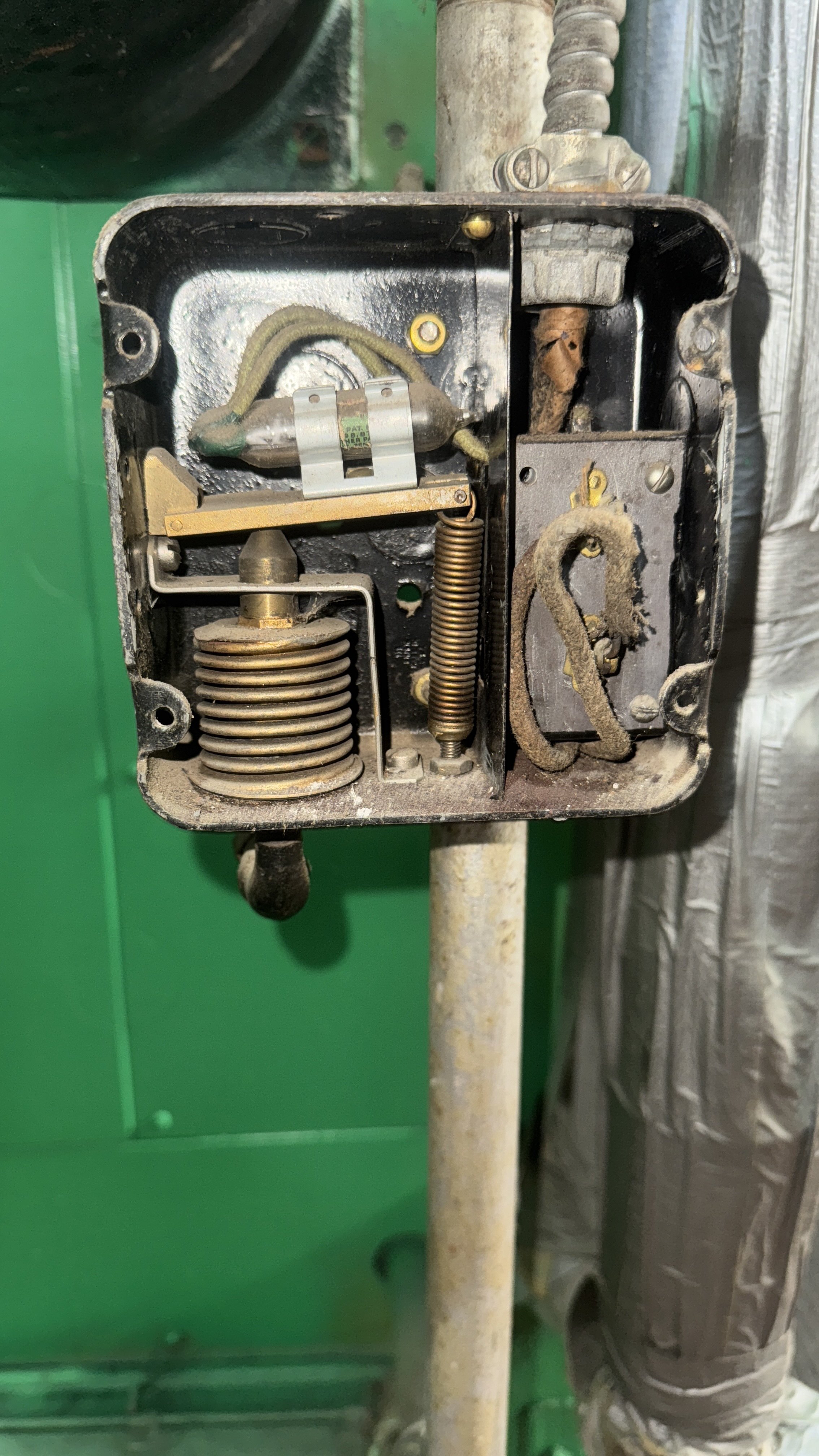
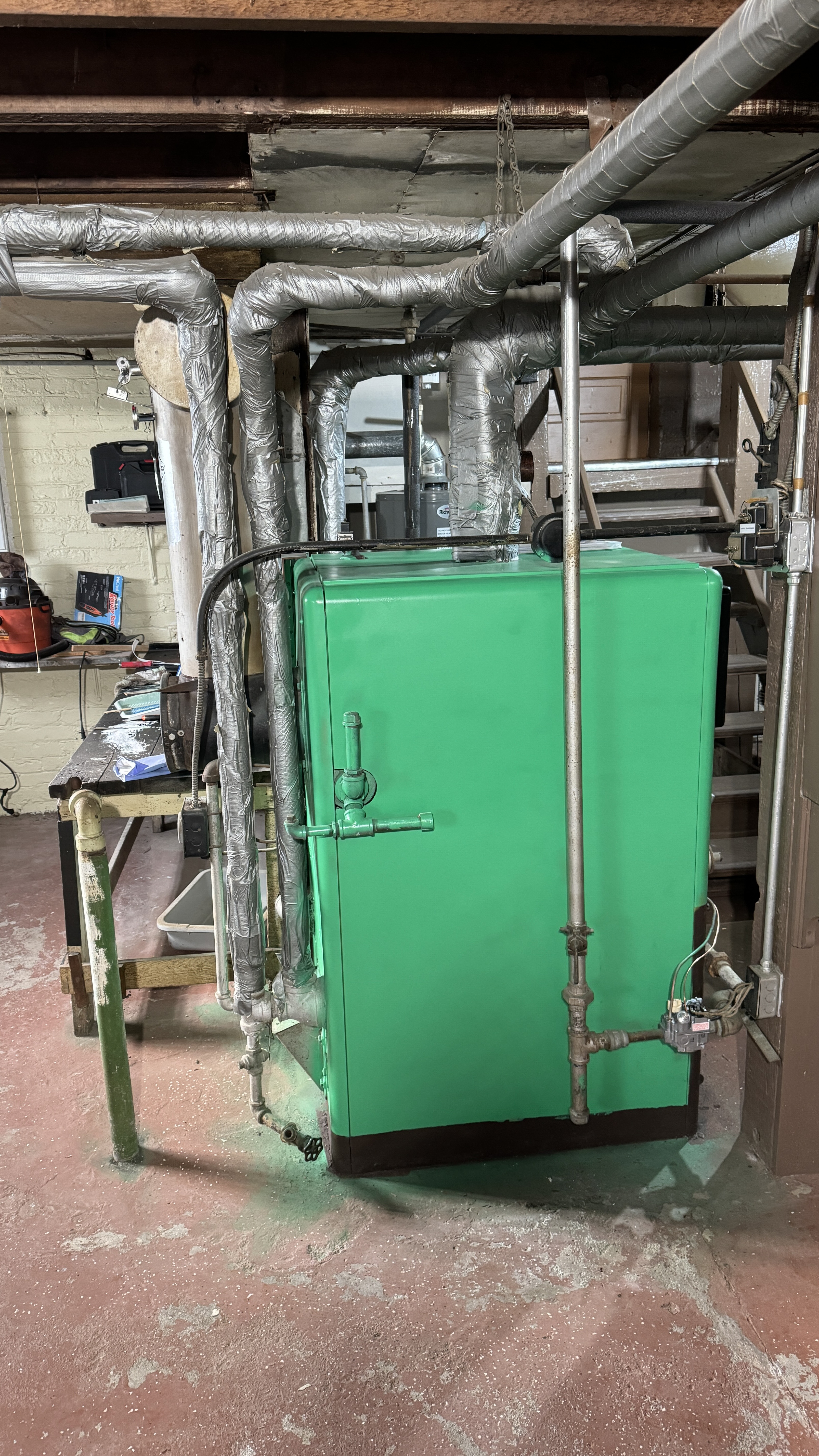
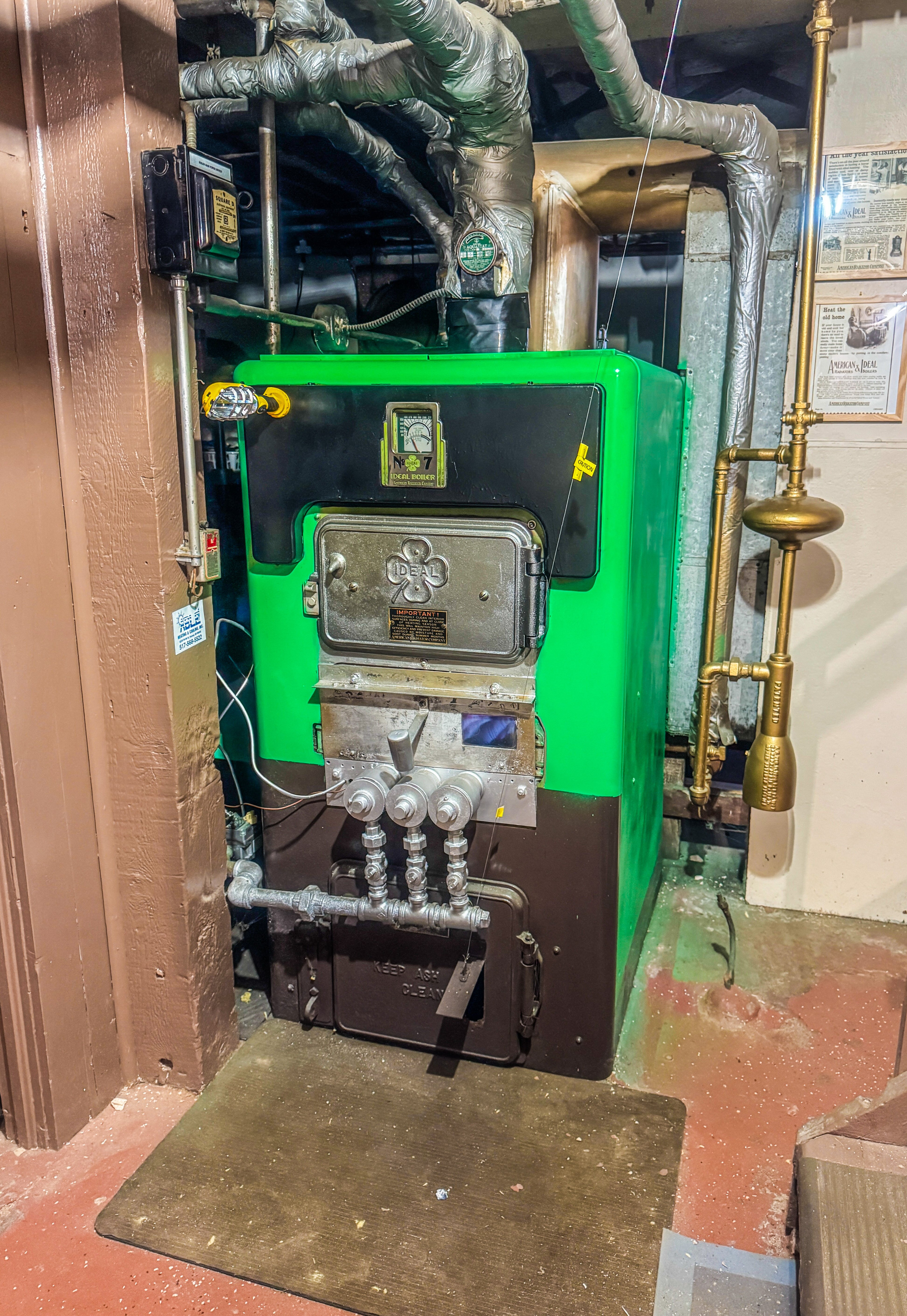
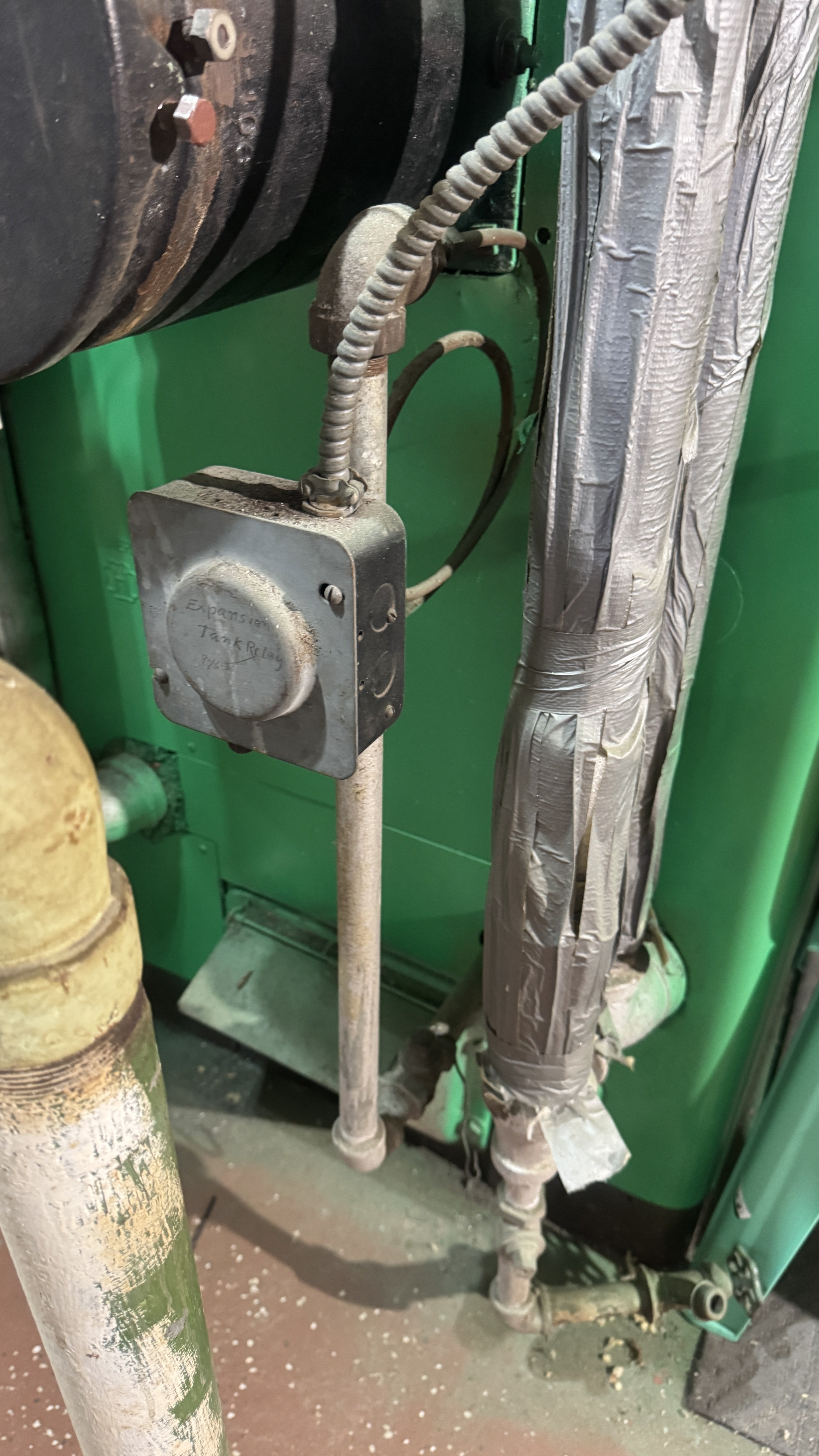
I have always wondered what this box is on the back of my 1937 ARCO hot water boiler No.7 was used for. Written in pencil on the cover is “Expansion Tank Relay” and a date of April 1937. It is fully defunct. Although there are electric wires, none of it is live. My home is still fully 100% gravity with no circulators. My expansion tank is in the attic and there are no type of wiring up there. This is also where I fill the system with water.
Please see my virtual tour in pics here. It’s takes you on the full path from this mystery box in the back to the front main shut off. In that picture you can see some old wires that are disconnected inside and taped. Once again, using my non contact voltage tester the taped wires are not live.
Btw, I’m in Michigan and I have already fired this beast up a few nights. We have already been experiencing some 39°-42° nights.😅
Thank you!
Lifelong Michigander
-Willie

Comments
-
looks like a pressure switch that determines if the system is sufficiently filled from the weight of the water in the pipe to the expansion tank. If it opened a feed valve or shut down the burner is another question.
 2
2 -
Pressure switch and the way the mercury switch is installed and the location of the spring and the bellows, it will function as a shut off on low pressure — that is, if the water level falls in the system, the switch will open.
Now how low is a very good question!
Br. Jamie, osb
Building superintendent/caretaker, 7200 sq. ft. historic house museum with dependencies in New England 1
1 -
I can't tell where the pivot is. it kind of looks like the bellows are cracked on the top left. Is there a label inside the cover?
0 -
There are no labels inside the cover.
Lifelong Michigander
-Willie
0 -
I think — and I could well be wrong! — that the switch is mounted on what looks like it might be a wooden arm which is hooked under something on the left side. The bellows pushes up on that arm, and the spring pulls down. But… without actually standing there fiddling with it, I could be all wrong!
Br. Jamie, osb
Building superintendent/caretaker, 7200 sq. ft. historic house museum with dependencies in New England1 -
That spring with the screw at the bottom adjusts the setpoint. I think the arm is some sort of phenoilc or phenolic soaked paper or cloth but i can't quite tell if the pivot is on the left or right or at some 3rd point we can't see. If you lift where the bellows contact it, it should tip. Where the pivot is will dictate if it is close on rise or open on rise. I am still surprised that there isn't a manufacturer's label inside somewhere. Even though it is in a 4 square box, it is clearly was made in a factory.
The lever might be ceramic or brass too, hard to tell in that picture.
1 -
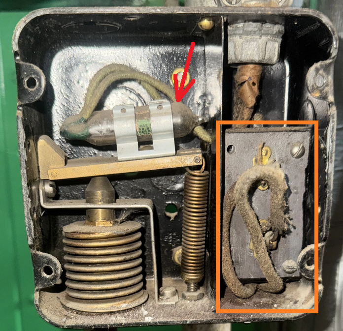
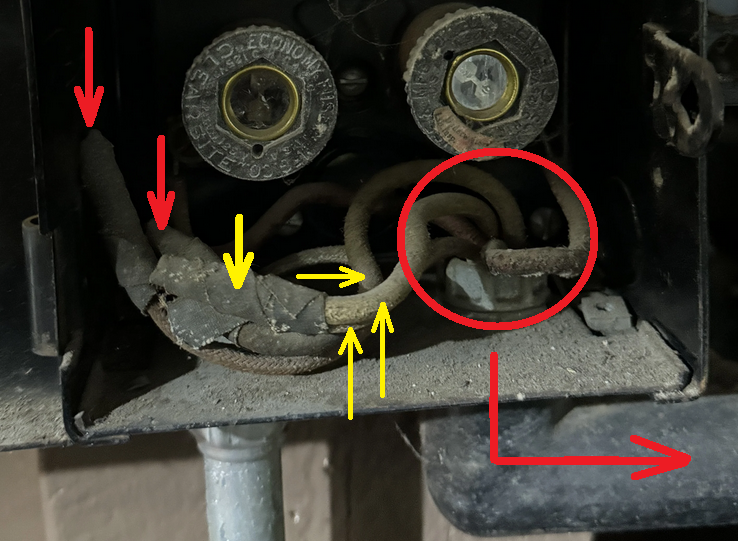
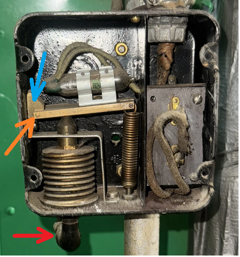
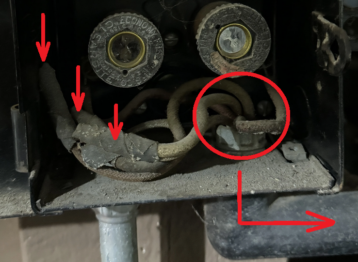
Depending on your level of curiosity. I'd clean off the dust (Red Arrow) on the Mercury switch to see which end the glass tube the contacts poke into the Mercury, probably the wire end but you never know.
Also the wire insulation changed between the Mercury switch and the connections inside the Orange box and the wires that enter the box. So is that a terminal strip, a fuse holder, a relay, other device?
Be careful with non contact electrical testers, if that Mercury switch actually switches the Neutral side of the circuit and the switch is closed (circuit live and active) the non contact electrical tester may not alert until the switch opens. I see taped wires AND also other wires. If you explore, Be safe, open the knife switch and remove the fuses !!!
 National - U.S. Gas Boiler 45+ Years Old
Steam 300 SQ. FT. - EDR 347
One Pipe System1 -
orange box is a terminal strip to connect the field wiring to the leads of the mercury switch. the contacts of the mercury switch are on the end with the leas. spdt mercury switches have a wire on the other end for the other contact.
0 -
I am leaving well enough alone lol. I’m not interested in reactivating or touching anything. It was obviously disconnected for a reason and I’m ok with that. But still was curious and knew some here would get a kick out of it and actually know what it did. 😃
Lifelong Michigander
-Willie
0 -
where does the bx go? perhaps there was an oil burner on there at some point before the gas. there would be no reason to use bx for a safety for the gas burner.
0 -
OK as long as you are sure " It was obviously disconnected for a reason and I’m ok with that. "
I see 3 taped wires and maybe 5 wires going into the conduit. To me it may still be in service. When I see something like that I assume it is live until proven otherwise. Taped wires in this situation is no proof.
" I am leaving well enough alone lol. "
If you don't touch it you will be good.
National - U.S. Gas Boiler 45+ Years Old
Steam 300 SQ. FT. - EDR 347
One Pipe System0 -
I only see one piece of bx with 2 wires going in to it.
0 -
Looks like it goes into a conduit that heads toward the knife switch disconnect / fuse box.
National - U.S. Gas Boiler 45+ Years Old
Steam 300 SQ. FT. - EDR 347
One Pipe System0 -
the 2 pole safety switch for a control transformer doesn't make sense either.
 1
1 -
For all I know about this situation they may have switched and fused the Neutral too. I trust nothing until I have proven it to my own satisfaction. Maybe 240, or two independent 120 branch circuits, who knows, and who knows where it actually goes ? It could loop through the Mercury switch on the Neutral side.
National - U.S. Gas Boiler 45+ Years Old
Steam 300 SQ. FT. - EDR 347
One Pipe System0 -
The BX which feeds the boiler master power switch travels up to the ceiling and across the basement to a junction box. Obviously being a junction box a few different areas are on that same circuit. Welcome to old house wiring.
My boiler is actually the only BX wiring in the house.Lifelong Michigander
-Willie
0 -
I think the BX that @mattmia2 was referring to was the BX that is going into the “Expansion Tank Relay” Box. And it looks to me that the other end of that BX it goes into a conduit that heads to a junction box and towards the knife switch disconnect / fuse box. The odd thing is that knife switch disconnect / fuse box has two circuits (apparently both are being used), when only one circuit is needed for a control transformer.
Yes old wiring can be strange at times. And there may have been burner changes over the years.
It all works, so your no touch policy is good for now.
National - U.S. Gas Boiler 45+ Years Old
Steam 300 SQ. FT. - EDR 347
One Pipe System1 -
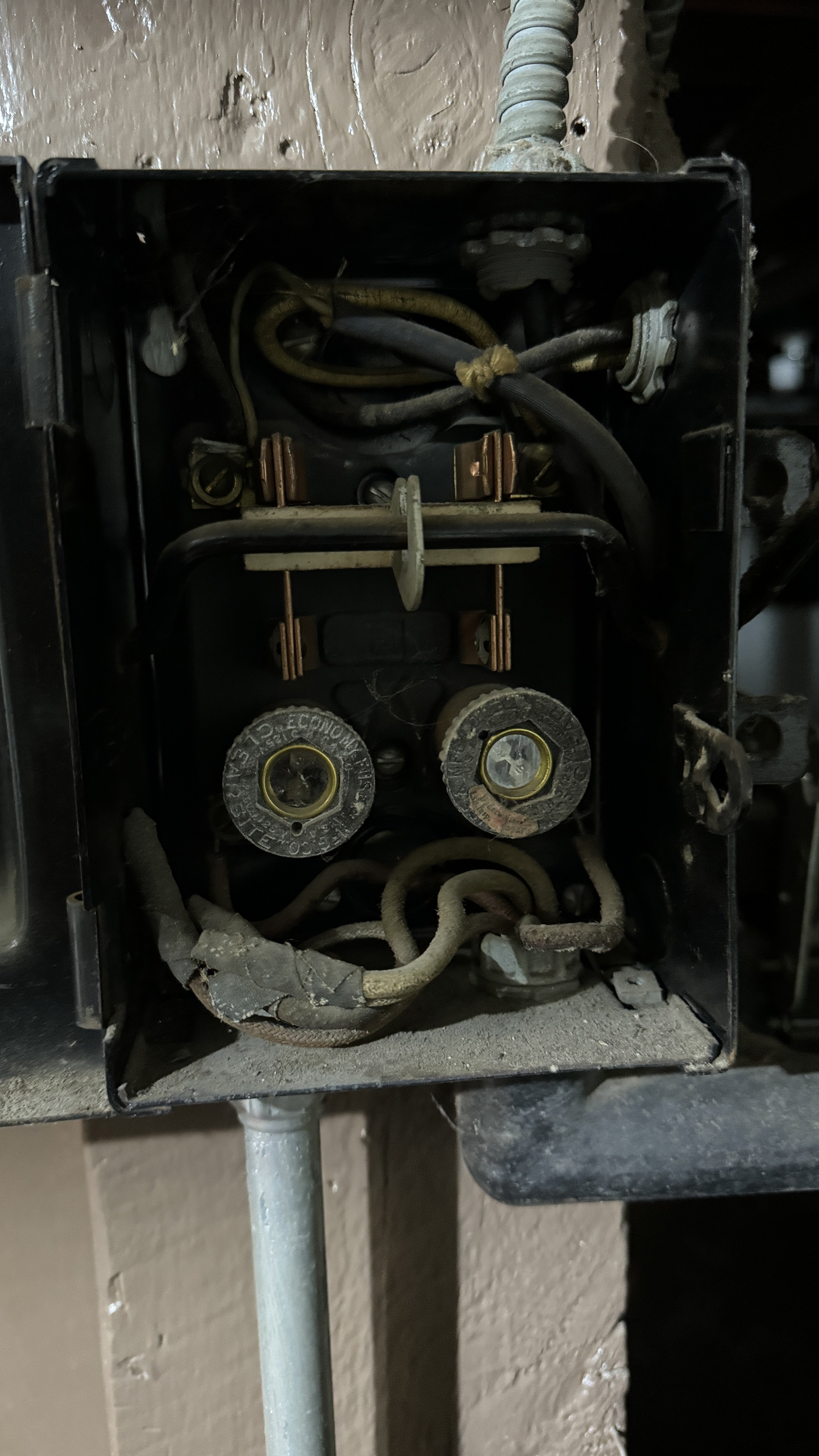
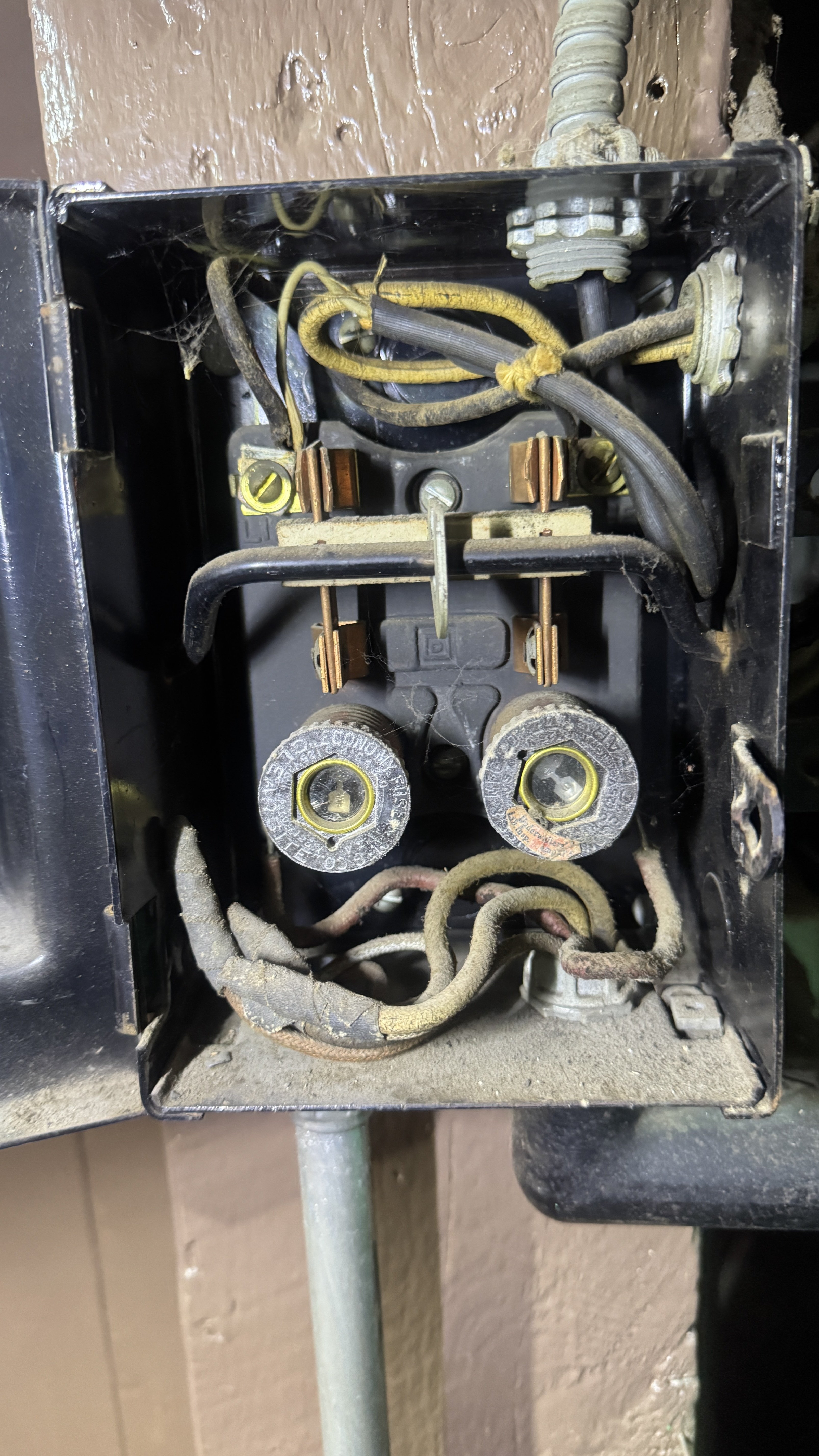
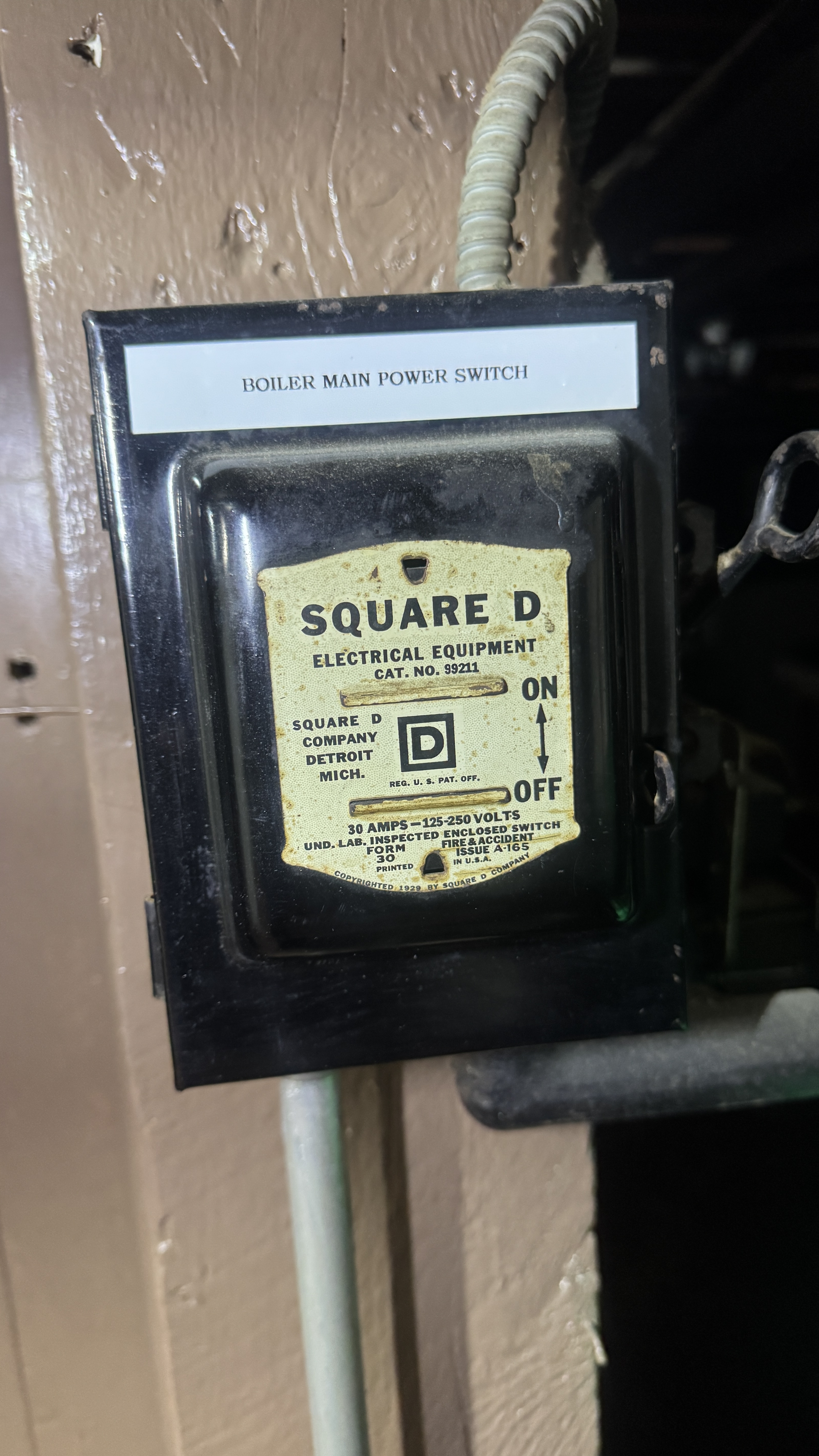
that is an enclosed safety switch, square d invented them, fused in this case. the d stands for detroit. they moved their remaining operations to chicago when we built an expressway through their campus.
they were commonly used as service equipment when 120/240v 30 a services were common.
1 -
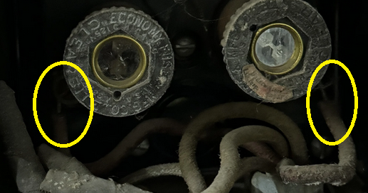
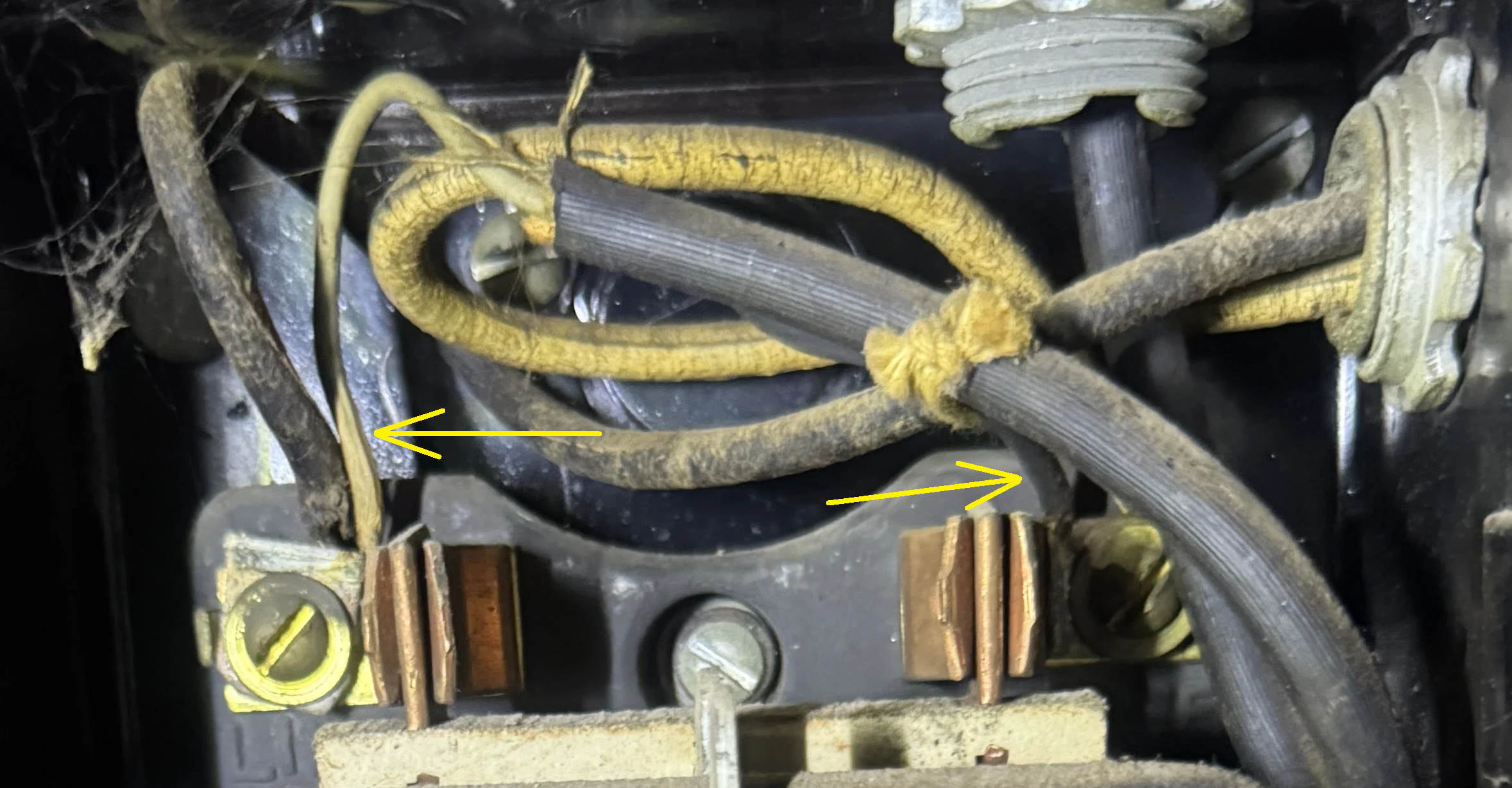
Looking at this closer at least one of the taped wires (Yellow arrows) is actually a connection of two wires, not dead ended.
 National - U.S. Gas Boiler 45+ Years Old
Steam 300 SQ. FT. - EDR 347
One Pipe System1 -
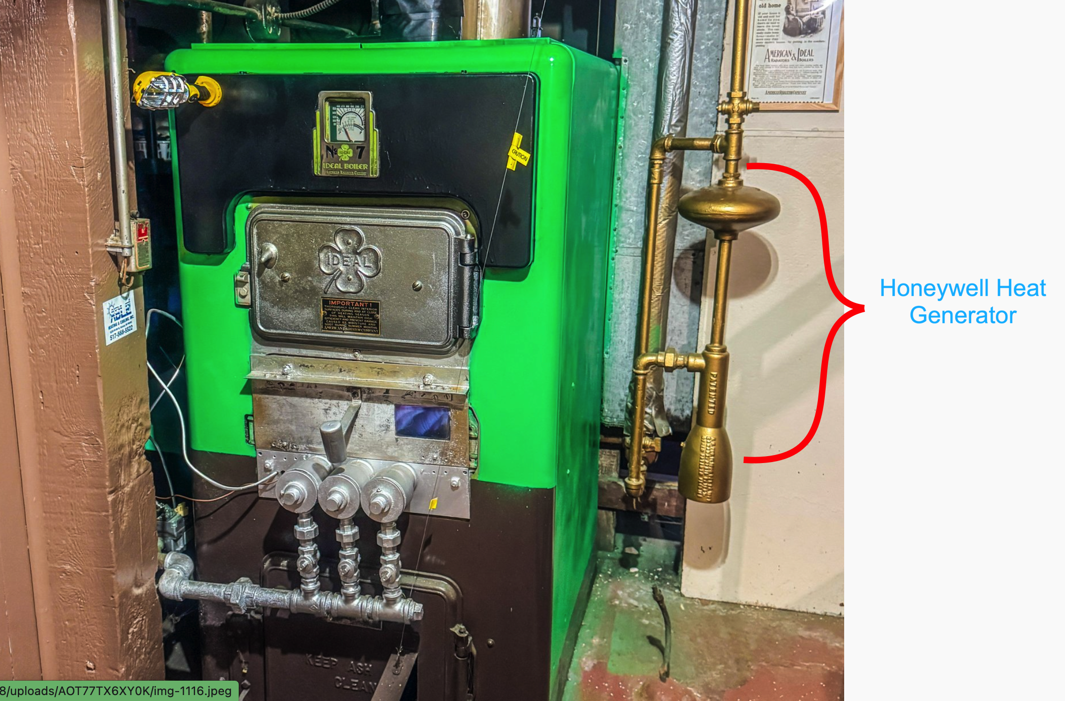
I believe you have a Honeywell heat generator. Don't make because this contraption is filled with mercury, and a lot of it! Click on the podcast link to learn about it.
The original expansion tank on that system was in the attic and may still be there. The Expansion tank switch was to make sure the pressure stayed at a safe level so the water temperature could get above 215° without steaming in order to use less radiators in order to compete with Steam boiler installers.
Edward Young Retired
After you make that expensive repair and you still have the same problem, What will you check next?
0 -
It would not surprise me if all the controls and limits are actually active. Looks like they are all tied together. It would also not surprise me if the Neutral is switched and fused and some of the controls and limits are switching the Neutral. Which it why you have to be very careful when using a Non-Contact electrical tester, they often don't tell the whole story.
 National - U.S. Gas Boiler 45+ Years Old
Steam 300 SQ. FT. - EDR 347
One Pipe System0 -
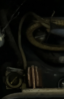
the baso switch is abandoned, it has a modern combination valve.
0 -
Yes I agree its functionality is abandoned, but the wiring through that switch housing may be tied together in that housing and could be on the Neutral side of the circuit.
National - U.S. Gas Boiler 45+ Years Old
Steam 300 SQ. FT. - EDR 347
One Pipe System0 -
looking at the other post and seeing that all the controls switch line voltage it likely had some sort of oil burner until the 50's or so when natural gas became available in the quantity needed for heating.
this looks a lot like a patch from a stack relay in the other post
the baso switch is normally in the low energy wiring to the gas valve.
0 -
Could have had a stoker too.
0 -
" the baso switch is normally in the low energy wiring to the gas valve. " That may be true but in this case it does not look like it was wired that way. And at least the newer ones are rated for the higher voltage.
National - U.S. Gas Boiler 45+ Years Old
Steam 300 SQ. FT. - EDR 347
One Pipe System0 -
It looks like there are some small wires in the safety switch too. the baso switch doesn't have a thermocouple attached so it isn't going to close but the only way to tell what is happening in that safety switch would be to trace it out in person without moving anything since that wire would likely shatter if you moved it.
0 -
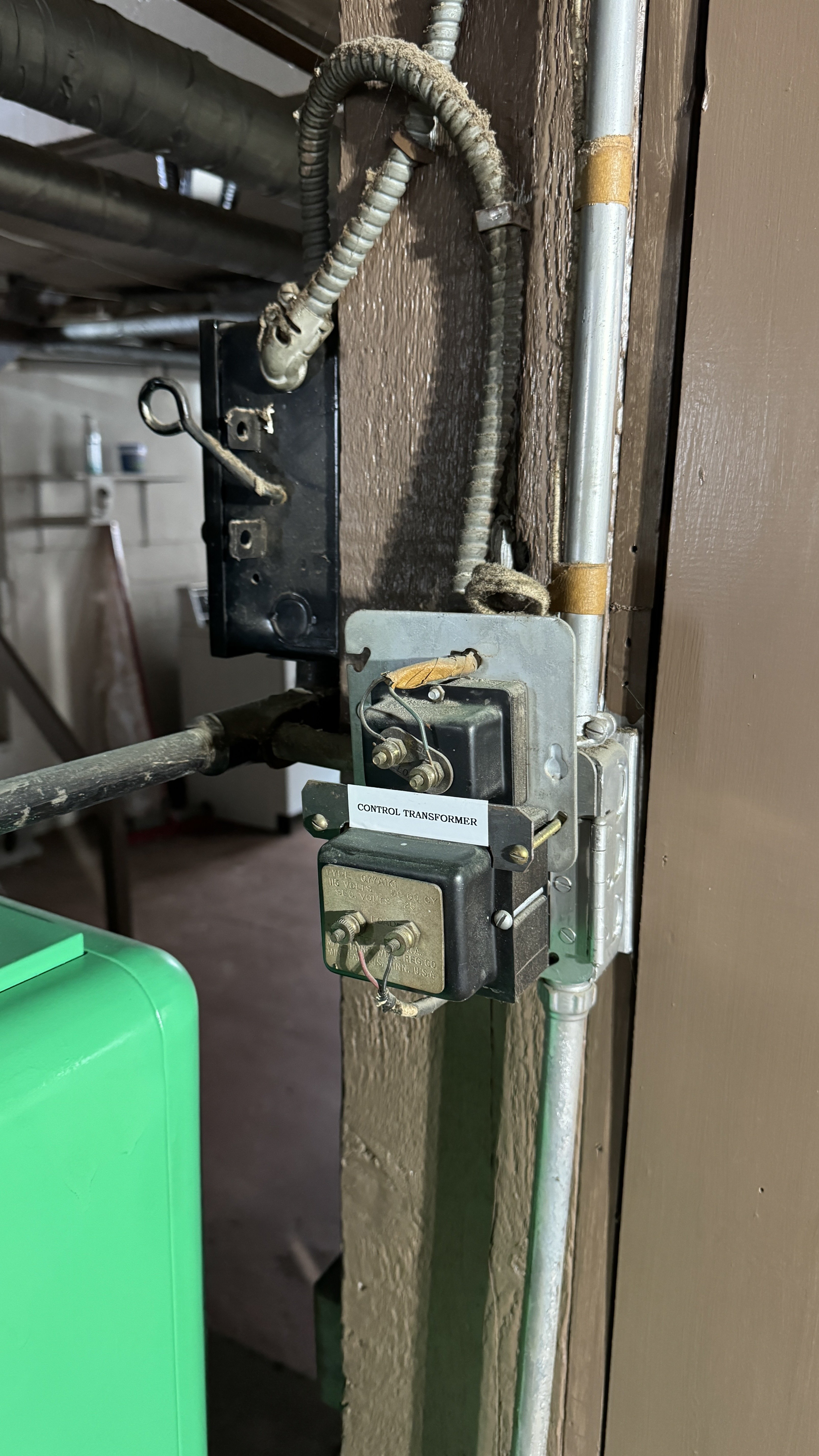
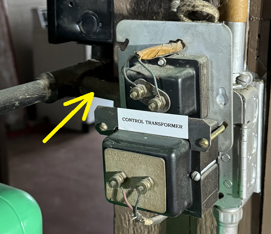
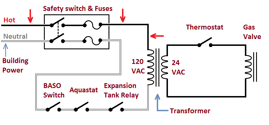
It appears to me the small wires in the upper part of the safety switch is a piece of SJ or appliance cord (Orange Arrow) that goes through a piece of flexible metallic conduit to the control transformer(s). I would say the thermostat and the Gas Valve are 24 VAC. The BASO switch (probably bypassed), Aquastat and the Expansion Tank Relay are all on the 120 VAC side of the circuit and part of the circuit.
What I am not really seeing for example, is if the Aquastat opens the 120 VAC circuit how does that shuts off the primary of the control transformer. Although it appears there is another path to the control transformer(s) through another conduit.
Yellow arrows, another taped wire connection, not dead ended.
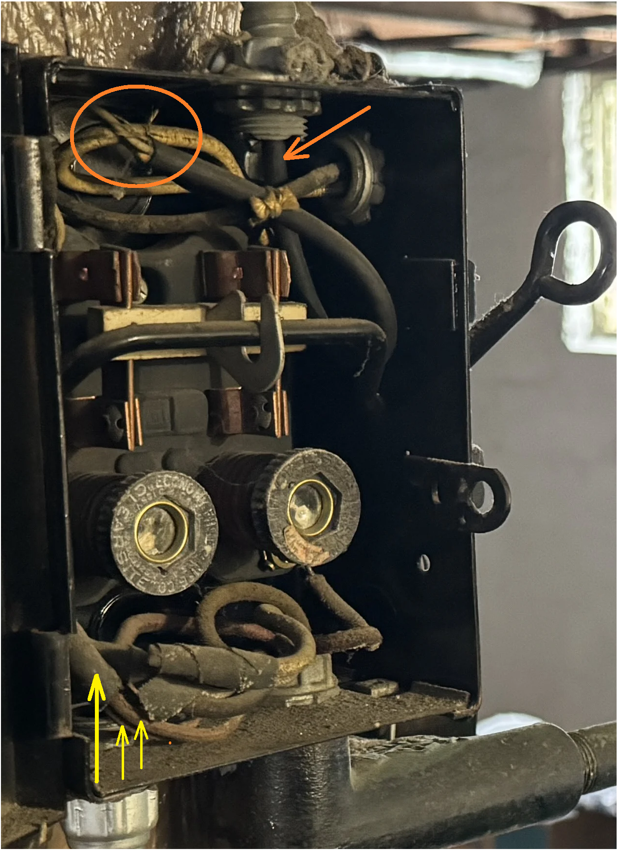
Also the Neutral looks Switched and Fused, at least some of the Neutral. It looks like the Neutral to the piece of SJ or appliance cord is under the screw on the line side of the switch.
 National - U.S. Gas Boiler 45+ Years Old
Steam 300 SQ. FT. - EDR 347
One Pipe System0 -
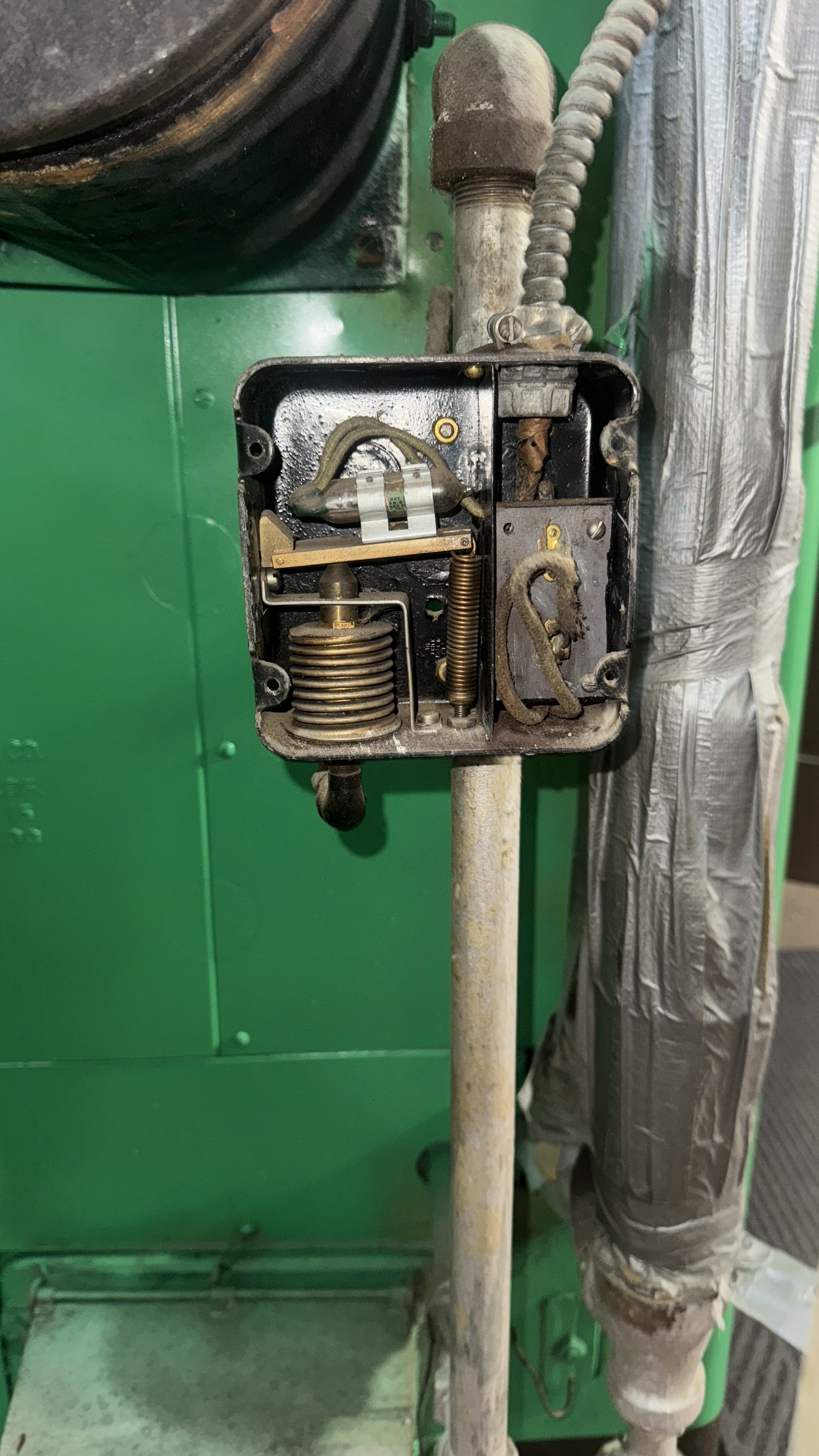
Back to the original question. I believe the Orange arrow is the pivot and the item the Blue arrow points to is secured to the box on the Left side. It looks like the system pressure (Red arrow) is still applied to the Bellows or Sylphon. As others stated, I believe it is a Low Water Cut Off safety limit. If the water level gets too low it should shut off the burner. Can you post a picture of the left side of the box ?
 National - U.S. Gas Boiler 45+ Years Old
Steam 300 SQ. FT. - EDR 347
One Pipe System0 -
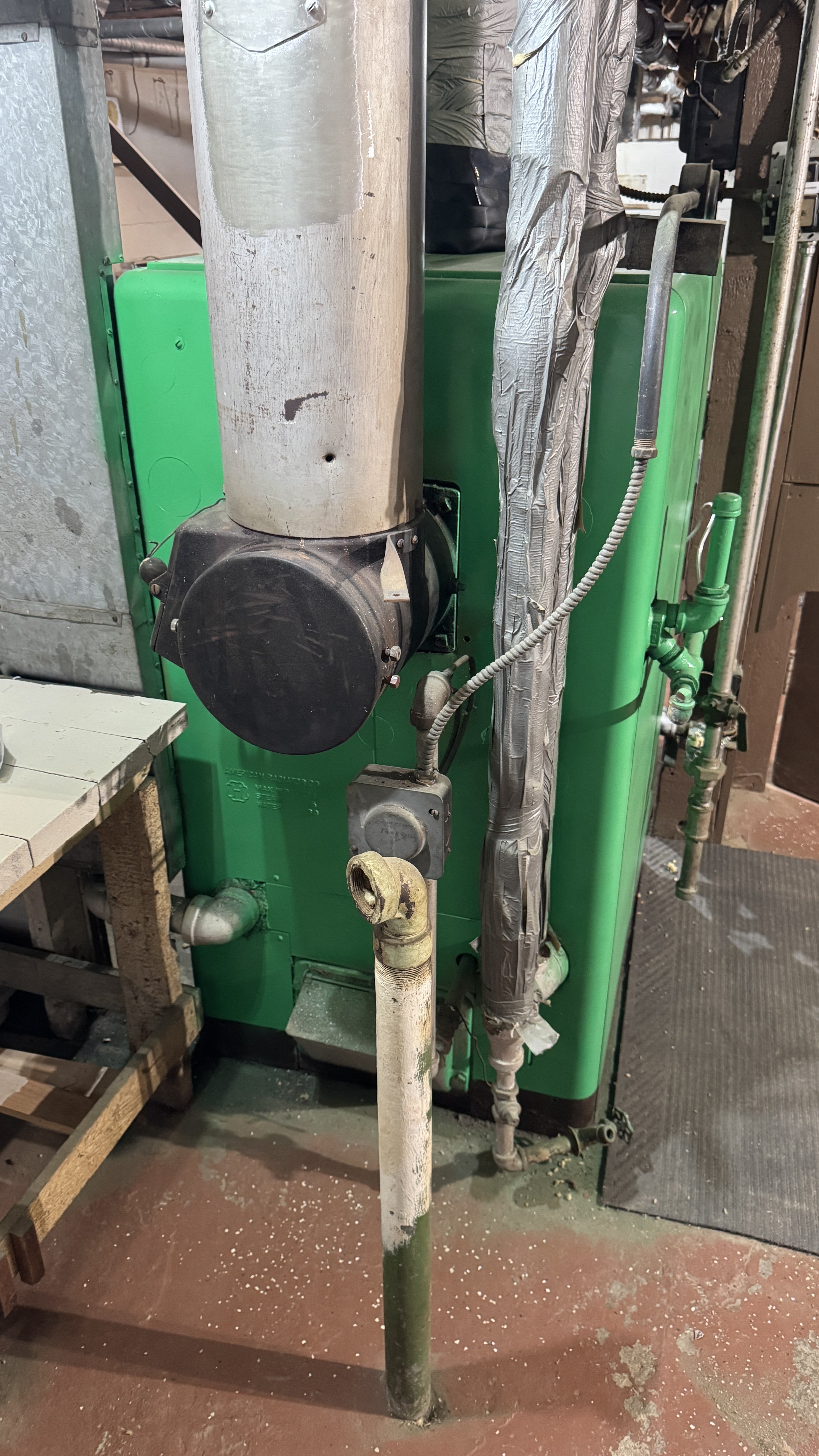
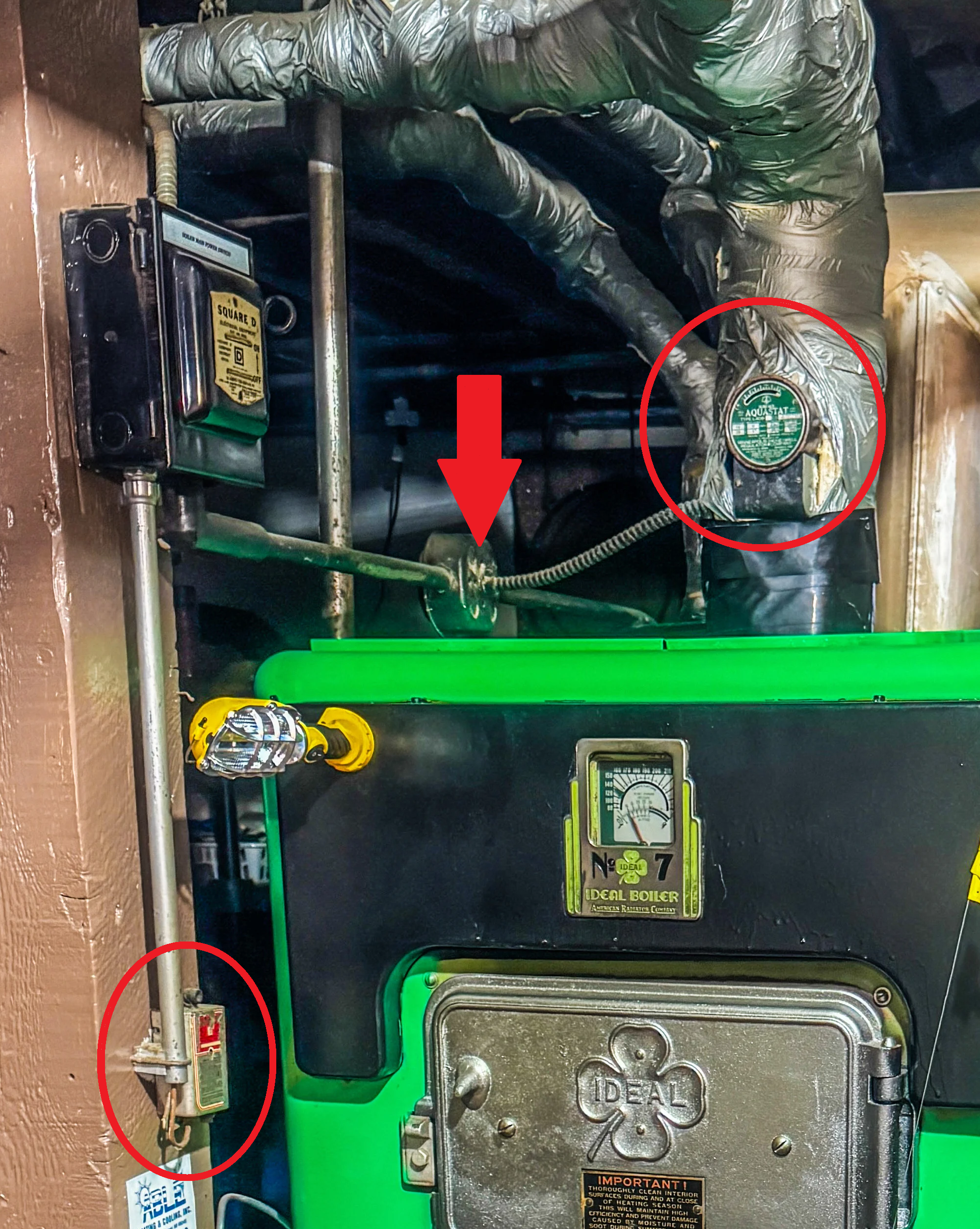
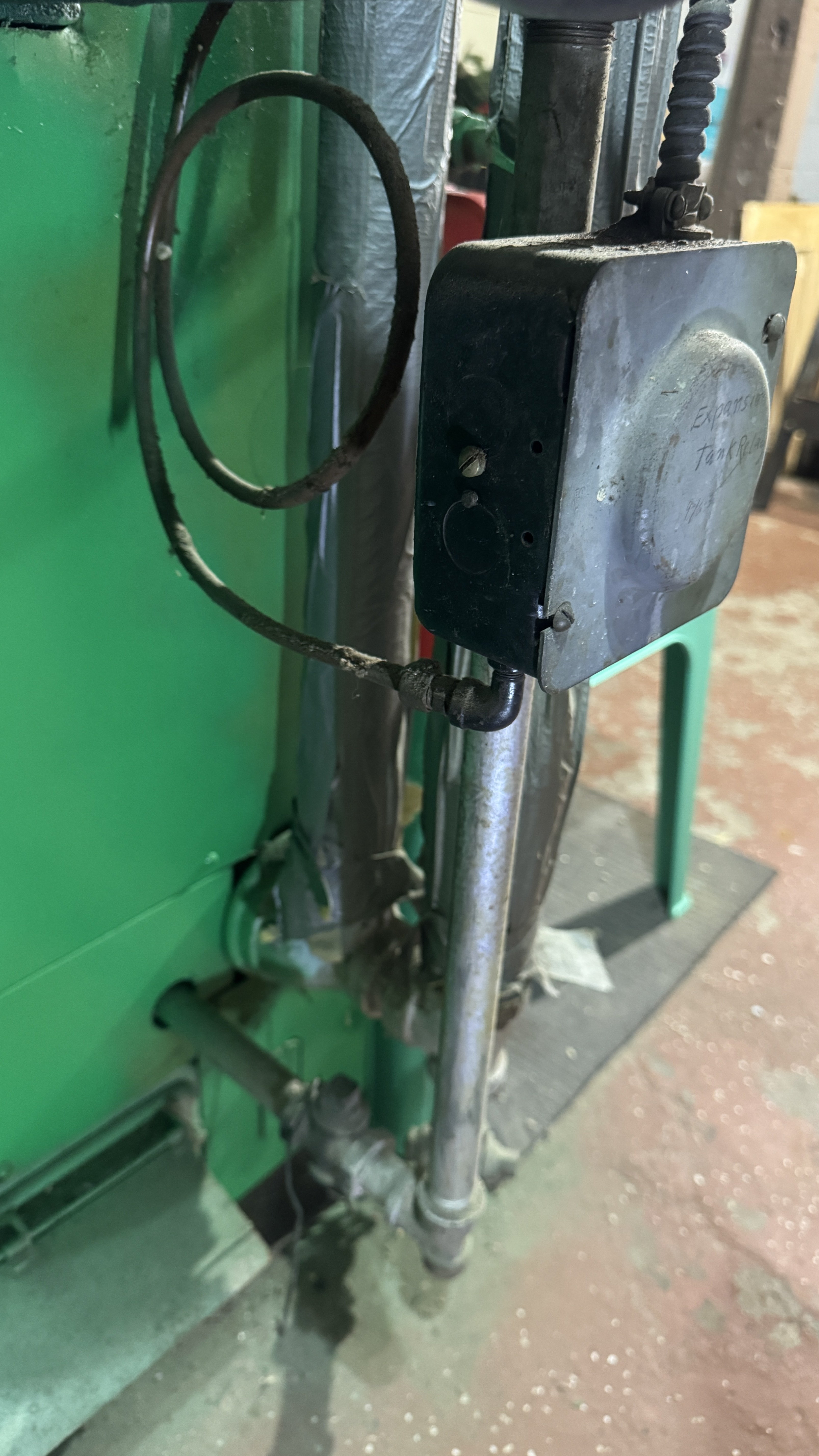
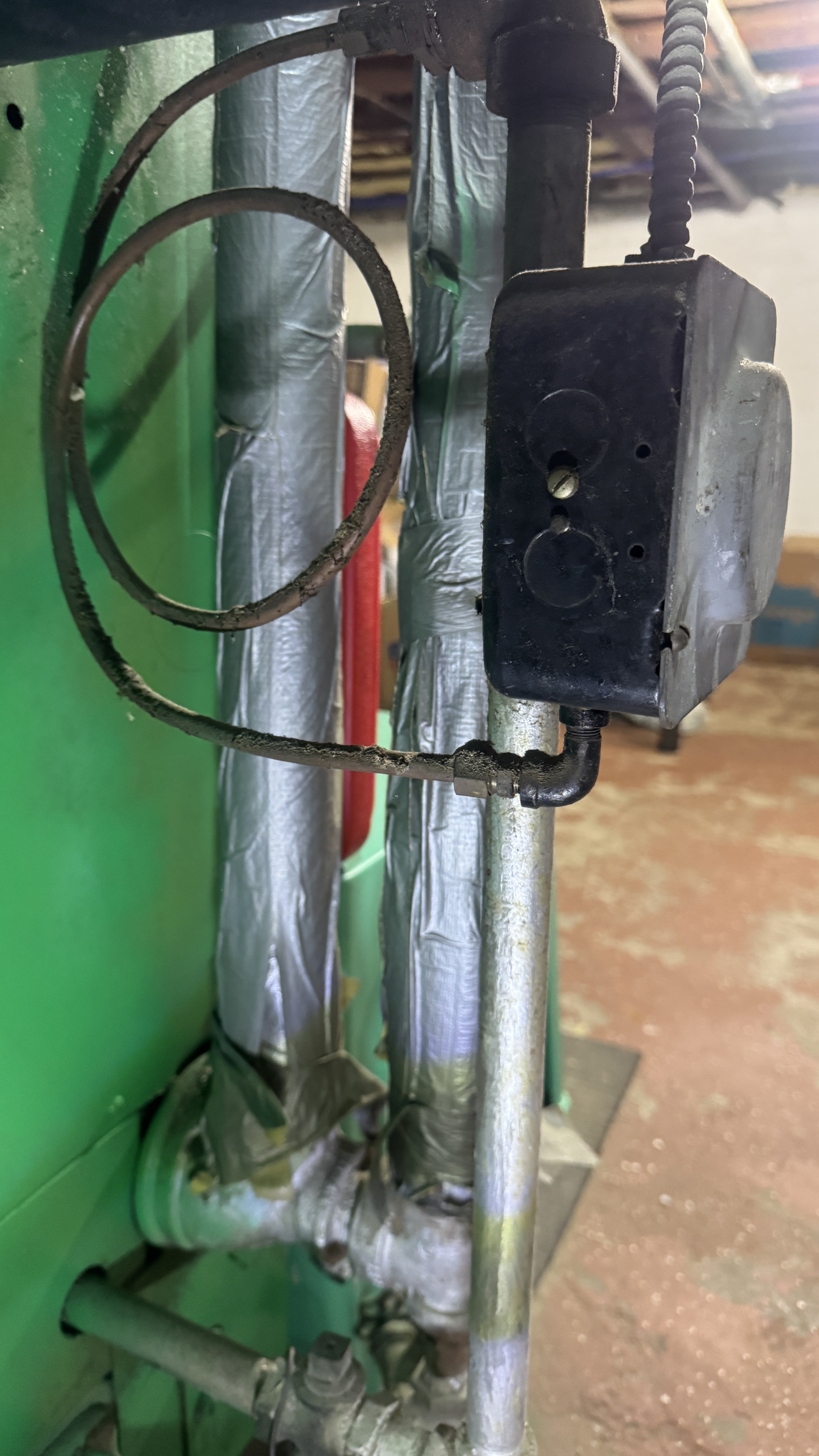
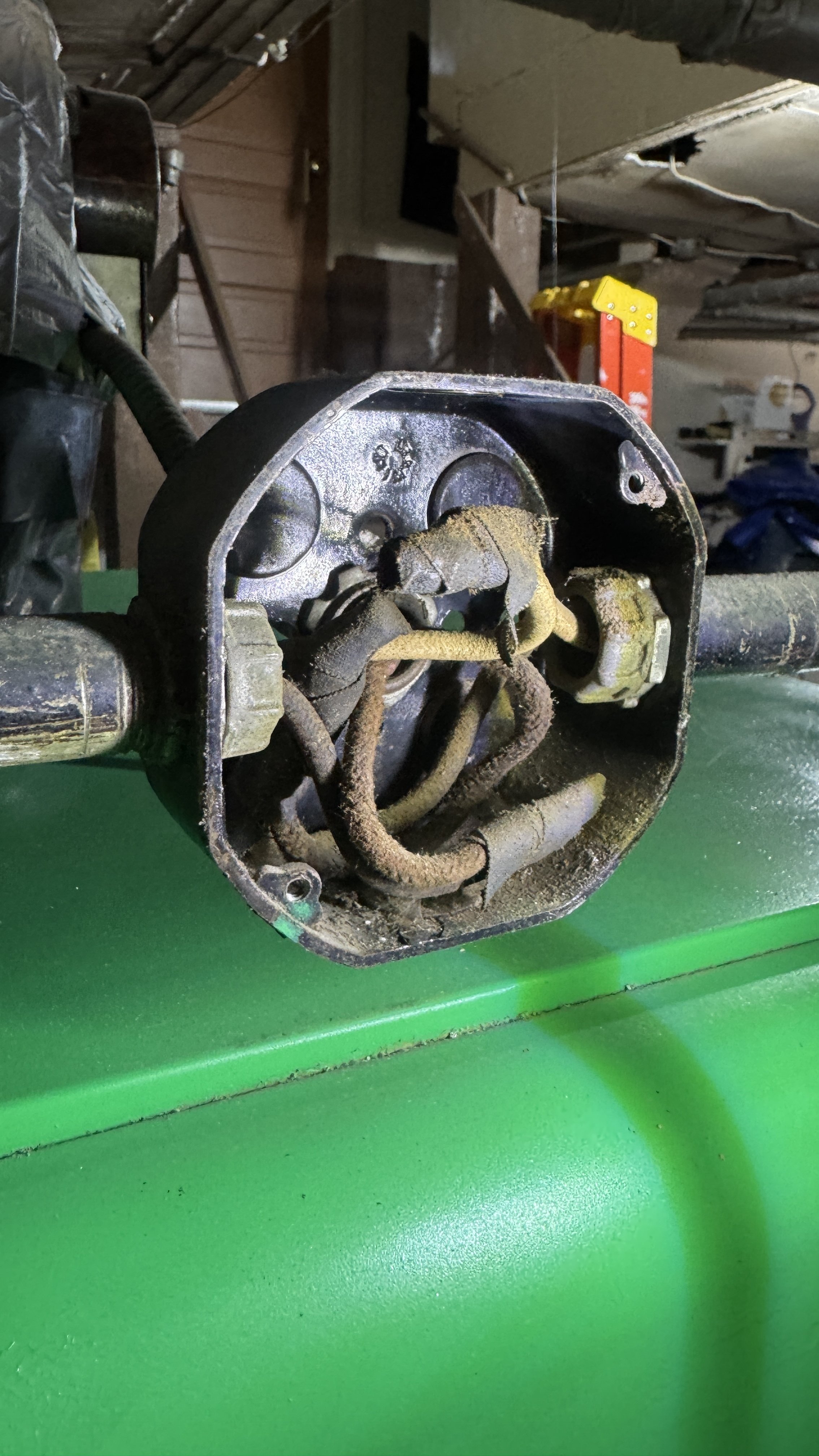
@109A_5 @mattmia2 I love this forum. Only here can make go down taking pictures of my boiler in the morning before heading to work lol. As requested here are a few extra pics of the relay area. Your suspicions appear valid that this was some type of low water cut off. Taking pictures this thing does feed into the boiler near the bottom. I'm not too concerned about low water though as my boiler has the working gauge letting me know how high the water is in the system.
I also confirmed that everything past the main shutoff is fully dead (see video link) including the aquastat. It's all just for vintage show at this point. And I am perfectly ok with that because the system operates marvelously. Even got it working with my Google Nest, so this baby is smart now lol and I get data and statistics!
This gravity system has been chugging along 116 years, and this boiler 88 years. This was an upgrade the original owner installed. Which makes me think the original boiler was probably one of the round tube boilers.
I recorded videos and got more pics of the main power switch with more lighting too!
Clips:
https://share.icloud.com/photos/087pyBy8iCO7BSuk16PGn75ZQ
The aquastat junction box:
Lifelong Michigander
-Willie
0 -
@EdTheHeaterMan Thanks! Dan (and you on my older post) got me all together early on when I bought my home teaching me about the Honeywell heat generator and gravity hot water heating with his youtube videos. I have also purchased his book How Come. The man (and knowledgeable others like you) are national treasures. So many techs today have no clue about any of this stuff.
I was able to find some vintage manuals on archive.org for the heat generator as well. I also believe the Heat Generator is way older than the boiler and was attached to the previous boiler that would have been installed. These ARCO No.7 boilers didn't get released until 1937 but my home was built in 1909 so there definitely was some other beast installed. 7 of my 11 rads are ARCO branded Rococos, so the original owner definitely had a preference in what he chose during construction.
Lifelong Michigander
-Willie
0 -
Thanks for the pictures.
Well I hate to say, the Non-Contact testing in the video proves nothing. If the Hot wire happens to go directly to the primary of the control transformer (the load) all the other wires connecting the Limit and safety switches would be at Neutral potential which usually does not alert a Non-Contact electrical tester.
Also (so far) I see no evidence that the wires to the BASO switch (probably bypassed at that switch), the Aquastat and the Expansion Tank Relay are disconnected and actually out of service.
If you are comfortable doing so, completely remove the Right hand (Neutral) fuse and repeat the test in the video. See if your dead wires are now Hot.
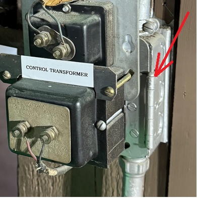
What is the upper transformer for, the Doorbell ? I suspect the thinner wire in the upper half of the box that the colors don't match the incoming power wires only powers the upper transformer.
Does the safety knife switch actually shut off the boiler ? If so the boiler's control transformer is not powered by the thinner wires in the upper half of the safety switch box, since the thinner wires are on the line side of the switch and are not interrupted by the switch or the fuses.
 National - U.S. Gas Boiler 45+ Years Old
Steam 300 SQ. FT. - EDR 347
One Pipe System0 -
Not sure if you are good with schematics / wiring diagrams. I believe your system is basically wired like this. In normal operation the Non-Contact electrical tester will typically only alert along the wires where the Red arrows are, the Hot wire. As a test, removing the Neutral fuse (only) effectively makes makes more of the circuit Hot through the primary of the Transformer (since the Neutral would be disconnected for the test).
 National - U.S. Gas Boiler 45+ Years Old
Steam 300 SQ. FT. - EDR 347
One Pipe System0 -
@109A_5 The knife switch does control the boiler. My doorbell transformer is at the front of the house. I’m not touching anything. As I said, I’m just happy with the vintage showpieces. When my thermostat calls for heat, it fires right up. That’s all I need. As the people who put this in is long gone, I already get the speech from local HVACs how I need to replace it because it’s old. Not because of issues, it’s just old 🙄. So I am not about to mess with something and it stops firing.
Lifelong Michigander
-Willie
 1
1 -
Well that is all up to you. I just find in life the better I understand something the better I can service it myself. Knowledge is power, as they say. I'm going with your safety's and limit switches are connected and operational since I see no evidence that they are not. They just switch the Neutral side of the 120 VAC, which will work, just not typical with today's wiring methods.
I encourage you to keep that boiler and the rest of the system as long as possible, I see no significant reason to change it.
I just hope whoever wired the system last maintained the integrity of the safety's and limit switches. They do have a purpose. Not just vintage showpieces. They are there to protect you, your family and your property. Boilers do fail and leak, and I would guess it would happen when you are not looking at the Gauge, rather when you are asleep or at work (both long periods of time). I've come home from work to find failed water pipes leaking into the basement, sadly it happens with older houses.
I do kind of wonder what the second transformer is for if it is not powering the Doorbell or the NEST, it looks a lot older than a NEST anyways. Maybe it is doing nothing. What appears to be a hinge is interesting.
 National - U.S. Gas Boiler 45+ Years Old
Steam 300 SQ. FT. - EDR 347
One Pipe System0


Categories
- All Categories
- 87.6K THE MAIN WALL
- 3.3K A-C, Heat Pumps & Refrigeration
- 59 Biomass
- 429 Carbon Monoxide Awareness
- 124 Chimneys & Flues
- 2.2K Domestic Hot Water
- 5.9K Gas Heating
- 119 Geothermal
- 168 Indoor-Air Quality
- 3.8K Oil Heating
- 78 Pipe Deterioration
- 1K Plumbing
- 6.6K Radiant Heating
- 394 Solar
- 15.9K Strictly Steam
- 3.5K Thermostats and Controls
- 56 Water Quality
- 50 Industry Classes
- 50 Job Opportunities
- 18 Recall Announcements