ECM pumps interfering with each other

I recently installed 3 Grundfos Alpha pumps in parallel. I noticed upon commissioning, that when 1 pump is running, it's pumping at 9 GPM. When the other 2 pumps come on, it drops to 6.5 GPM. Likewise, the 1 pump will also interfere with the other two. I'd like to keep all the pumps running at the higher GPM's. Have all my ECM pumps piped in parallel been acting that way and I just didn't notice? Is there a way to deal with this?
Comments
-
what do you mean by "in parallel"? are they actually in parallel or are they on a manifold feeding different zones?
0 -
 0
0 -
 0
0 -
The flow through any centrifugal pump — including ECM pumps — is determined by the relationship between head loss and flow rate. The head loss to flow rate relationship is fixed by your piping.
So, when one pump is running, the system balances at your 9 gpm or so, with a certain pressure drop (head loss). When you try to run two pumps more or less in parallel (and your system has sections where the flow of two or more pumps is combined), the flow rate will increase — in total — in those sections, but so will the head loss.
Therefore the flow rates will not simply add, and you will have less total flow (in your example, 13 gpm) than would happen if they simply added.
Is there a solution? If there is a pump control option for constant flow, set that at 9 gpm and if the pumps have the capacity to generate enough head to run 9 gpm (combined would be 18 or 27 with all three running) they will. I don't think that is a an option, though — I think you have delta P and delta T options, neither of which will do it.
Br. Jamie, osb
Building superintendent/caretaker, 7200 sq. ft. historic house museum with dependencies in New England0 -
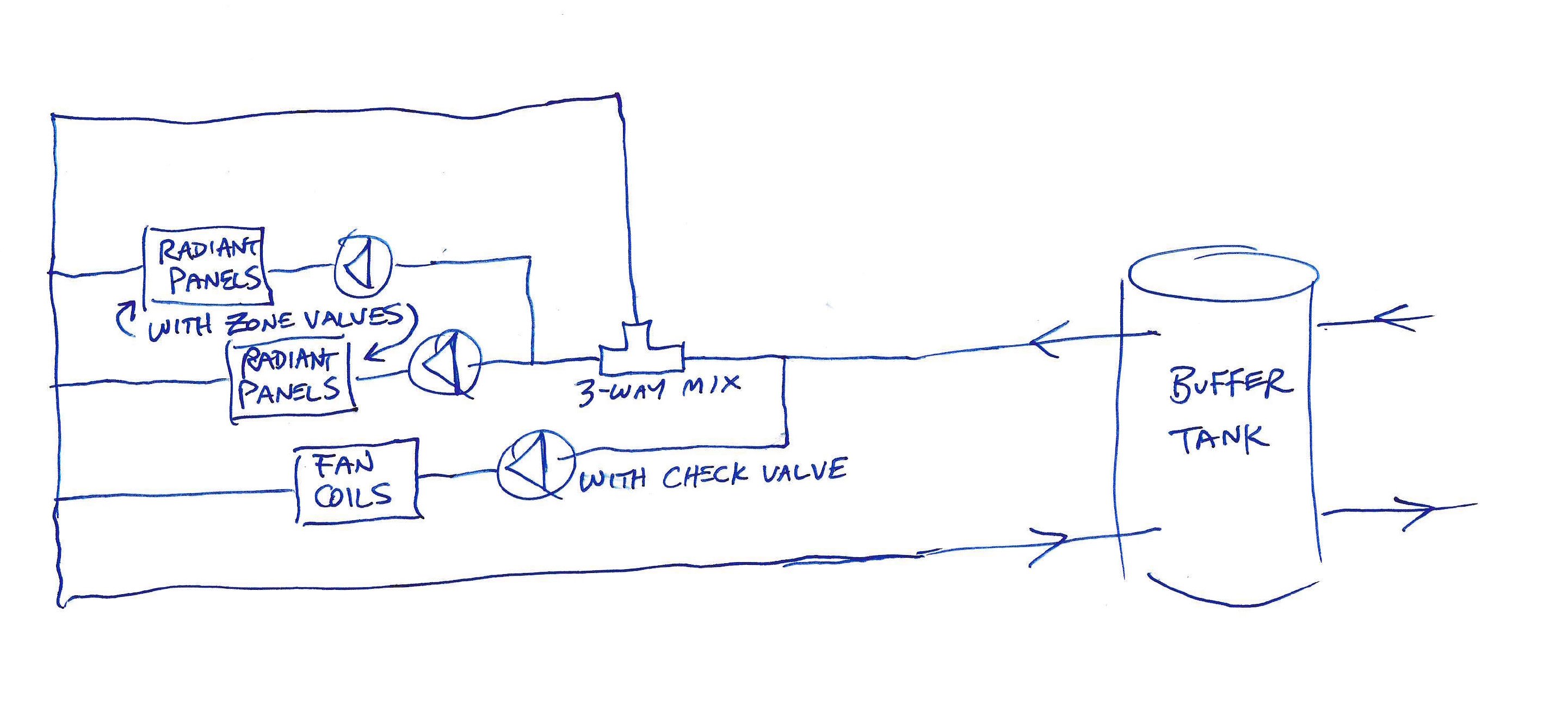
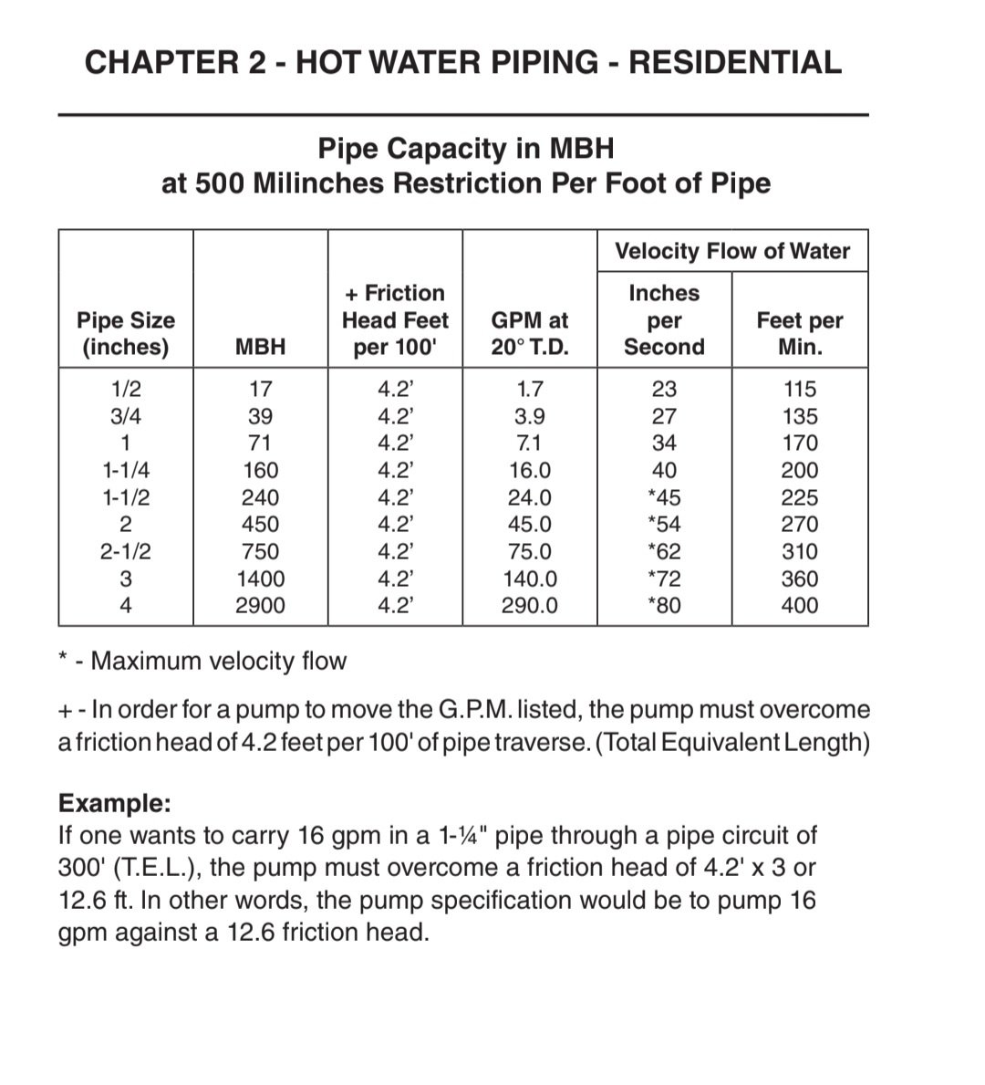
To put in picture form, you can get 9 GPM from all three pumps if you have the correct piping sizes.
With only one pump operating at 9 GPM you can use 1" copper and get all the flow you need. That is because 9 GPM can move freely and relatively noise free thru 1" copper. But 9 GPM is about the maximum you can fit in a 1" Copper pipe. more than that and the system will get noisy. (8 GPM is the recommended max flow for 1" Copper)
The problem happens when you try to move 18 GPM thru 1" copper. There is not enough room. So your original design needs to have 1-1/4" copper in order to accommodate the flow from 2 pumps. Even if some of the return water from the radiant loop goes back to the mixing valve there is still the chance that the return to the boiler will
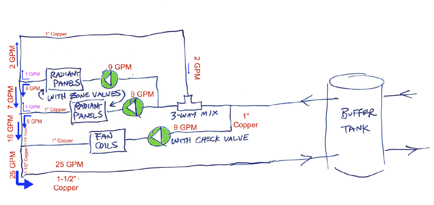
overwhelm the 1" return to the boiler or buffer tank.
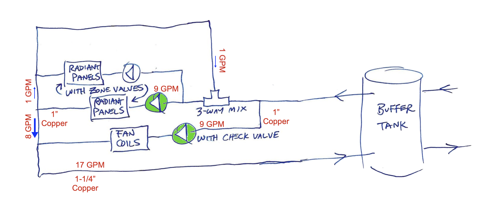
When you add a third pump, now you need to increase to 1-1/2" copper to accommodate 27 GPM in the shared piping.
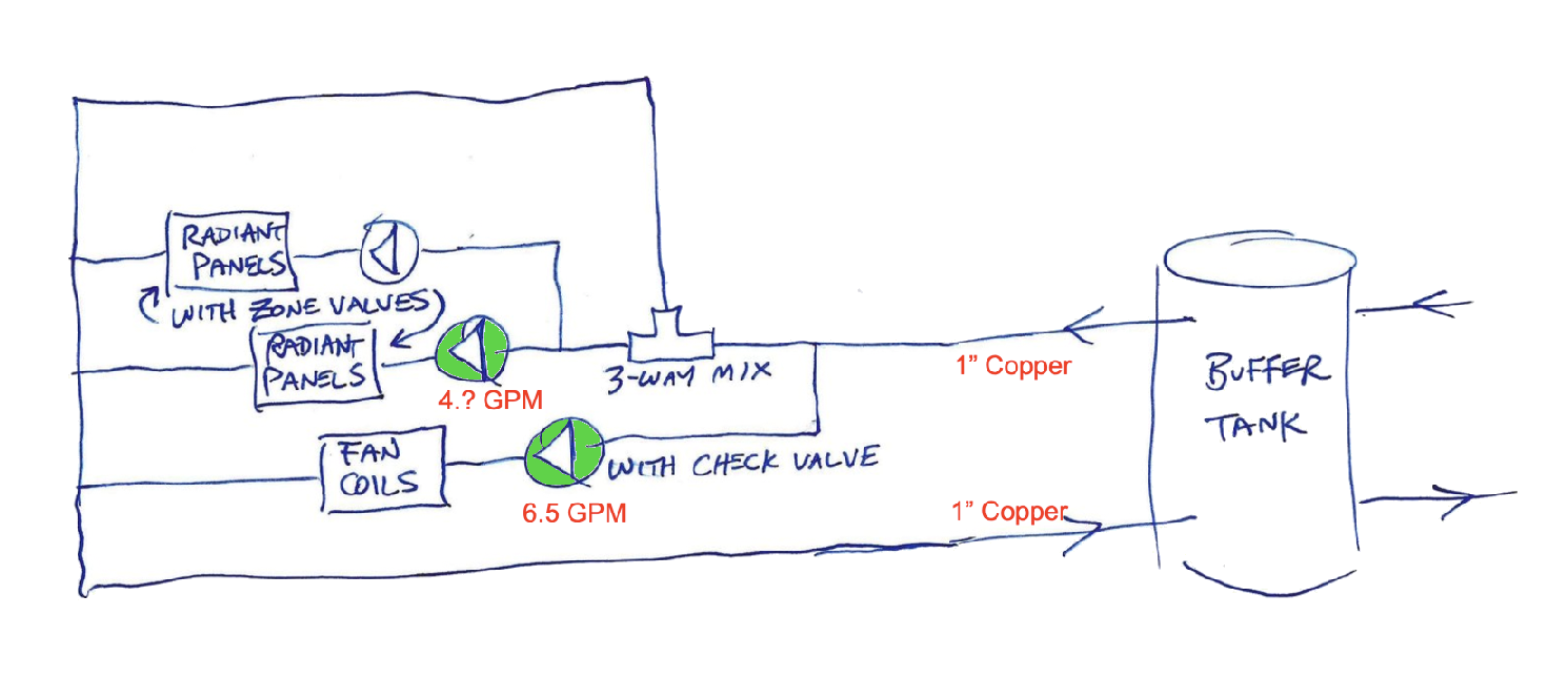
With 1" Copper shared piping, when more than one circulator pump is operating the pumps need to operate against a greater pressure drop or Pump Head as more water needs to move thru. the same space. So the pump curve will move from 9 GPM each, down to something lower, like 6.5 GPM as the other pump fights more friction from the mixing valve, radiant floor tubing, manifolds and the like. So pumps of equal capacity will move different GPM based on the friction loss of the zone it is operating.
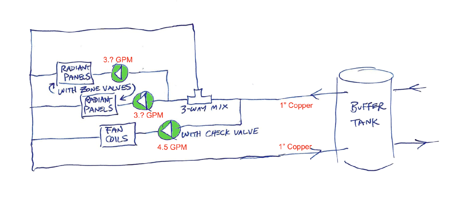
With all three pumps operating on smaller common piping, you will get even lower GPM from each pump. Designing piping systems you need to take into account the sahred piping and the flow rate under the worst case. All pumps operating at full capacity at the same time. If you don't take that into consideration, then you will end up with performance issues, short cycling, noise and many other. problems.
These diagrams should make things clear as mud for you
Edward Young Retired
After you make that expensive repair and you still have the same problem, What will you check next?
1 -
Follow up to my shared piping diagrams above. The numbers for GPM flow are estimated for discussion purposes only. The actual numbers may vary.
Edward Young Retired
After you make that expensive repair and you still have the same problem, What will you check next?
0 -
And the mixing valve has to be sized right they are a pressure drop to be considered and being on the suction side is more of an issue. Larger PB should be on the discharge side of the pump.
0 -
That makes sense. I installed 1-1/4" copper pipe from the buffer tank through the 3-way to the tee before the radiant pumps. The fan coils circuit is piped 1". I'm looking for about 7.5 GPM through the fancoils and about 6.5 GPM through each of the rad panel pumps. If I understand correctly, the pumps aren't interfering with each other as much as the piping from the buffer tank is undersized. If I had piped that in 1-1/2", then I wouldn't see the flow through one pump drop when another pump came on. Yes?
0 -
What gives you the illusion that you need this much flow? Also, the Alpha displays are a guess at best. Just because it says 9 GPM does not mean that it's actually 9 GPM. If you are actually wanting 20 GPM, that's 2" pipe territory but again, completely unnecessary
0 -
6 gpm per radiant loop sounds like a lot of flow?. You would want a high Cv mix valve for that.
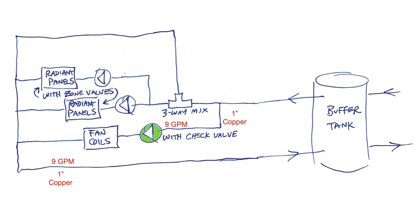
The piping from the buffer is your low liss header. It should be sized for 2-4 fps with all pumps running. So add all the gpm and size accordingly 1-1/4” should handle 16 gpm
type M copper? Here is 1-1/4 and 1-1/2”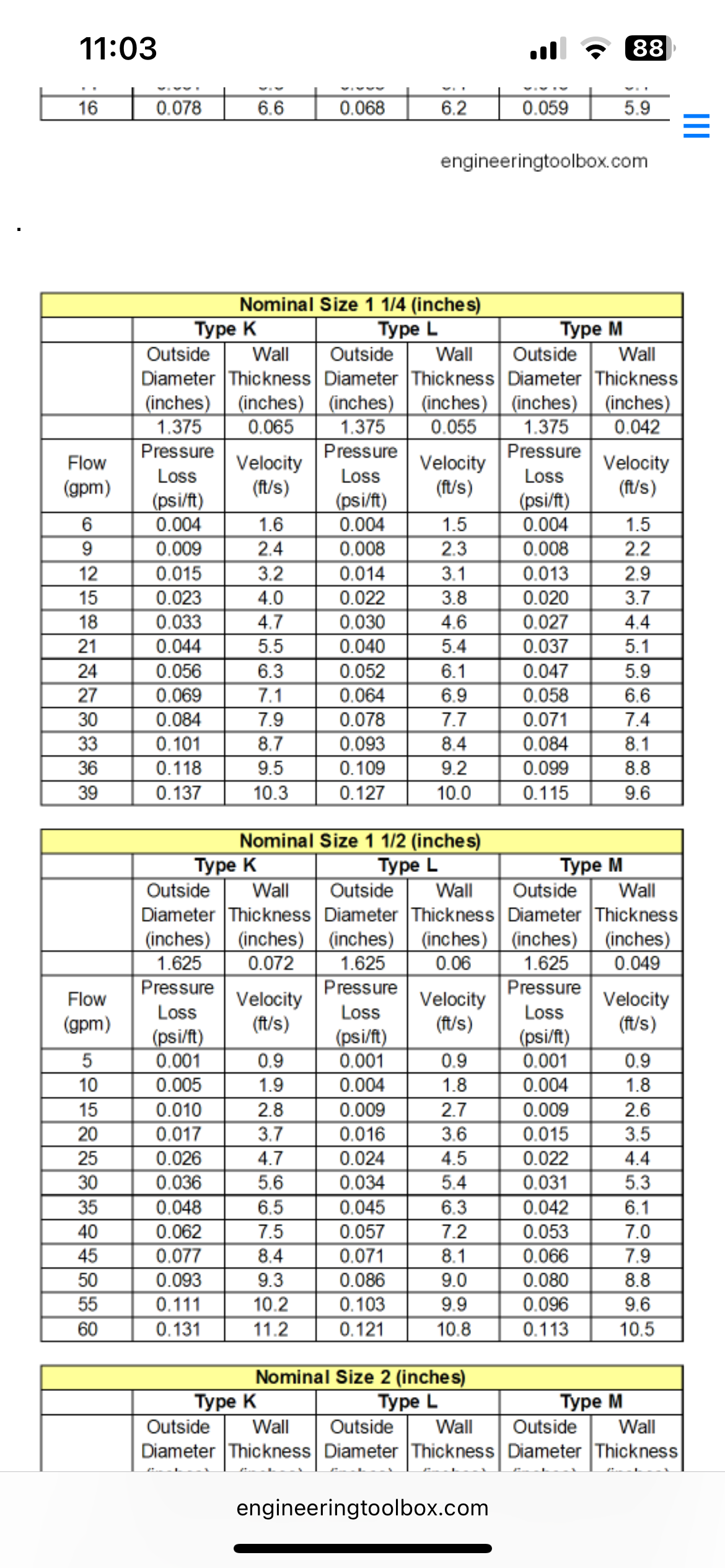
With a three way mix valve the pump pull from the MIX port
Bob "hot rod" Rohr
trainer for Caleffi NA
Living the hydronic dream0 -
Agree with this. But you may not be looking at the big picture. You may not need 7.5 GPM to the fan coil(s). by your diagram, you show only one fan coil. How many Fan coils do you have?
Next thing to consider is what output are your heat emitters? If you are only heating a 30,000 BTU space with one fan coil, you can do that with 3 GPM thru the fan coil, with a 20° temperature drop from the supply to the return.
You might find this booklet interesting: Zoning Made Easy. I used this as my text book for teaching a one day seminar. Page 4 and 5 will be helpful in understanding how GPM and Temperature Drop (∆T) all play a role in transferring heat. Knowing the numbers will help you know if your pipe sizes are large enough or not.
Also, if your boiler NET heating output is only 50,000 on its highest fire and you have a ∆T of 20° thru the radiant floor loops, then you will only need 5 GPM total for both loops. 10 GPM if you have a 10° ∆T. So knowing the big picture can save you on oversizing pipes and pumps. Just because a pump CAN pump 9 GPM, does not mean you NEED 9 GPM. Look at the entire system.
Edward Young Retired
After you make that expensive repair and you still have the same problem, What will you check next?
0 -
Each radiant pump is serving many loops. The fan coil pump is serving 3 fan coils. This is great information. Thank you.
 1
1 -
Are the many loops all operated by one thermostat? …or are you zoning from the manifolds with several valves? You can have 20 loops with 10 on one mix valve and 10 on the other mix valve operated by 2 thermostats. …or you can have 20 loops with a valve on each loop operated by more thermostats. This will help folks like @hot_rod select the right pump based on minimum and maximum GPM needed based on how the different zones call for heat. The bottom line is comfort, with a little "No Water Flow Noise" as a close runner up. Always keeping in mind that we need to keep short cycling the burner to a minimum.
Edward Young Retired
After you make that expensive repair and you still have the same problem, What will you check next?
0 -
It's a mix of zoning. 1 rad panel pump might serve one manifold with a zone valve and another with multiple actuators on the manifold. I'm getting between 1/2 GPM to 3/4 GPM to each loop throughout the home, with the Alpha pumps.
0 -
Regardless of what pipe size you use starting one pump and looking at the flow and then starting the second pump and looking at both flows you will see changes. Once all the piping is done and the system is filled and bled you have to run all the pumps to balance the flow in each circuit or zone.
Undersized pipe will make things difficult or impossible to balance. Correct size pipe will make things easier.
0 -
which Alpha do you have? The newest version allows more choices to keep flows stable. Balance valves can do that also. They are used to fix over- pumped conditions often.
Adjust the math when you design around different deltas. The 10,000 btu / gpm only works with a 20 delta. Your radiant may be designed for 10-15 delta?
As @EdTheHeaterMan mentioned, the boiler output, assuming it is sized properly, is the limit to btus you can emit, and the limitation to required pipe size. A 50k boiler should be able to move all its capacity through a 1” pipe?
1/2” Pex in a radiant look .65-.75 is about the max without needing a high head circ.
Bob "hot rod" Rohr
trainer for Caleffi NA
Living the hydronic dream0 -
The model number of your boiler, the total square feet of radiant floor, along with the total number of radiant loops and the total length of the tubing per loop would be helpful in looking at the big picture. We are all just guessing here as to the actual size. My 50,000 BTU was just an example for this discussion. We would like to know what you actually have.
Boiler size / model number is a good start before you start measuring everything else.
Edward Young Retired
After you make that expensive repair and you still have the same problem, What will you check next?
0


Categories
- All Categories
- 87.6K THE MAIN WALL
- 3.3K A-C, Heat Pumps & Refrigeration
- 59 Biomass
- 429 Carbon Monoxide Awareness
- 124 Chimneys & Flues
- 2.2K Domestic Hot Water
- 5.9K Gas Heating
- 119 Geothermal
- 168 Indoor-Air Quality
- 3.8K Oil Heating
- 78 Pipe Deterioration
- 1K Plumbing
- 6.6K Radiant Heating
- 394 Solar
- 15.9K Strictly Steam
- 3.5K Thermostats and Controls
- 56 Water Quality
- 50 Industry Classes
- 50 Job Opportunities
- 18 Recall Announcements