Connecting AC to Hydronic System
Comments
-
Also to satisfy my OCD, is it ok if I switch the RIB24P's NO poles and use Yellow/Orange for the Fan connections and Purple/Brown for the Taco connections?
Thank you again Ed and have a good night!
0 -
After doing some reading, but I'm not sure if this is right, is is it true that the Hydrostat 3200 Plus aquastat on the newer Peerless boiler has a built-in temperature sensor and low water cutoff (LWCO)? If so, does that mean it doesn't require a separate strap-on aquastat as it won't turn the fan on until the water temperature is at the appropriate temp?
It would make sense as the previous strap-on aquastat wasn't wired in properly and I didn't notice the fan blowing excessive cold air this past winter (however I may have just not paid enough attention).
0 -
the aquastat on the boiler controls the temp on the boiler, it keeps it from overheating if the system isn't removing the heat as fast as it is produced.
the aquastat on the air handler keeps the blower from coming on before the coil in the air handler is hot.
the blower speed has to do with the output you need from the air handler. at least in colder climates you usually need less airflow for heating to keep the air at a comfortable temp. with cooling you need a minimum airflow for the cooling power of the condenser to keep the refrigeration system at the right operating point. too little airflow and the coil can ice or it can flood refrigerant back to the compressor.
1 -
Yes, you can use the Prp and Brn as the low voltage.
I was concerned with the double wires on the Taco SR501 at the 5 and 6NO connections. You should only have one set of R and W wires there that go to the boiler.
Someone should really do what @EBEBRATT-Ed mentioned earlier. You need to have a master wiring diagram of the entire system from each thermostat to the zone controls to the AHU units to the Switching Relays to the boiler controls. Then when something dies not work, you can refer to the proper wiring diagram to see how they interact with each other. Saves time when someone is trouble shooting.
You don't know how many times my mechanics went to no heat calls to be baffled by some system like yours only to find that is was something simple like a fuse on the Power Vent system. They didn't even know there was a power vent system to begin with. When I get there to help them, (and also train them on the job) I find the power vent is not allowing the gas valve/ignition control to open and light the flame. the mechanic looking for 90 minutes with no luck. (I did that in the past) …only to find the problem in five minutes once I pointed to the power vent system.
I can help with that. Send me a PM message if you are interested.
Edward Young Retired
After you make that expensive repair and you still have the same problem, What will you check next?
1 -
@mattmia2 has the correct answer. The boiler temperature sensor connected to the HydroStat 3200 is measuring the temperature at the boiler. There is no provision in that control to operate one or two or seven different fans based on that near boiler temperature. in order to keep the fan from blowing cold air at the location of the air handler unit (AHU 3 for example) may have 80° water temperature when there is a call for heat while a different air handler has 160° water in the coil because there is a current call for heat. The boiler temperature may be 180° at that same time and actually turn of the burners so the temperature does not get to 190° (because the limit is set at 180°) at the boiler. If the AHU 3 is 100 feet away from the boiler (via the piping) it may take about 4 minutes before the water is hot enough at AHU 3 so is not blowing cold air.
Perhaps later today I can draw you the easiest way to connect the Strap On Aquastat. I'm heading to breakfast now. TTYL
Edward Young Retired
After you make that expensive repair and you still have the same problem, What will you check next?
0 -
Sometimes a job needs another set of eyes because you can't see the forest through the trees.
When I was in business my partner was an excellent tech. This didn't happen too often as he was a calm guy but he would call me up and he was pissed.
"you better get over here with your tools. I have been working on this all day and can't find the problem". I would walk in the door and he would explain the problem and I would say "did you check this or that" and the job would be fixed. Of course he would then be more pissed.
But the situation was reversed plenty of times when I couldn't find the problem

 3
3 -
Here is the updated wiring diagram for your Air Handler Unit for zone 6 (AHU 6). I have added some features to the diagram to include:
- The L6006C strap on aquastat to keep the fan from blowing cold air on start up. the fan will not operate unless
- The Fan Relay os in the Automatic or off position (thermostat set to Fan Auto)
- The Heat relay is on (thermostat calling for heat)
- And the coil temperature is at least 120°F (setting adjustable)
- The ability to use two speeds on the Fan motor. By routing the heat relay through the NC contacts there will be no problem with using a different speed on the fan motor for heat and a different speed for cool or Fan On.
- Changed the Heat relay colors to use the Prp and Brn to activate the Taco SR501.
These three changes will be a better design for future use by others in the event that someone decides that you may have a more efficient operation with a different fan speed on the blower fan motor or cool only but the leave the heat at the existing speed (or vice versa).

Note: AHU 6 and the outdoor condensing unit CU 6 may be fed 220VAC from separate circuit breakers. Make a note of what circuit breakers feed each unit on this diagram for future reference
I recommend this diagram be followed to ensure proper operation of the heat and cooling system. After completing this project and testing this system for proper operation, post this wiring diagram near the AHU 6 appliance and a second copy near the boilers. A third copy can be kept on file with other important papers.
PS. I know that we are using the L6006C Strap On aquastat is on the line voltage side of the system. This is for a good reason. If you try to use the low voltage side of the system to control that fan speed, you will end up with a "Catch 22". You need the aquastat to turn on the 24 VAC relay to heat the water, but the boiler needs the hot water to satisfy the aquastat. That is why you can't use the low voltage wires at the relay. The Heat Relay still powers the Taco SR501 but the fan won't operate until the water in the coil is hot.
Edward Young Retired
After you make that expensive repair and you still have the same problem, What will you check next?
 2
2 - The L6006C strap on aquastat to keep the fan from blowing cold air on start up. the fan will not operate unless
-
Nice that's very informative and extremely helpful!! Yes I was planning on printing the diagram out and taping it to the handler itself, in addition to saving a digital and hard copy for future reference.
I am very interested in creating a complete wiring diagram, will definitely help with future projects and troubleshooting. I'll send you a PM.
Also, I'll double check and see why there are 2 wires on the Taco 5 and 6NO connections and will report back.
I had a few additional questions:
- This zone that we have been working on (Zone 6) has an original similar design to Zone 7. There used to be an old zoning panel on each air handler (Trol-A-Temp) with 2 zones each (2 thermostats and dampers). The zoning panel for Zone 6 likely was discarded years ago and the zoning panel for Zone 7 seems to have failed within the past year. I recently installed a Honeywell HZ322 to Zone 7, which wasn't difficult as the Carrier air handler has a new and functioning control board. I was wondering if it would be difficult, or even impossible, to wire a HZ322 panel to Zone 6 due to all of our RIB relays and wiring? The reason I ask it because Zone 6 covers the entire front half of the main floor. However, each end of the home heats/cools differently and I believe would benefit from zoning. I don't believe a bypass duct was installed during the original installation, so to prevent a build up of static pressure, I wouldn't let the dampers completely close and keep them slightly open at 25%.
- I have an Aprilaire 500 whole house bypass humidifier. I originally had it connected to the coil of the RIB heat relay to turn on with a call for heat and the fan blowing. However, I unplugged it recently to work on the AC and wondering now what would be the best way to wire it back in now that we have changed the design?
- Your previous comment mentioned that Zone 7 had a convoluted sequence of operation. Are you suggesting that the system is complex but wired correctly or that the sequence of operation is improper?
0 - This zone that we have been working on (Zone 6) has an original similar design to Zone 7. There used to be an old zoning panel on each air handler (Trol-A-Temp) with 2 zones each (2 thermostats and dampers). The zoning panel for Zone 6 likely was discarded years ago and the zoning panel for Zone 7 seems to have failed within the past year. I recently installed a Honeywell HZ322 to Zone 7, which wasn't difficult as the Carrier air handler has a new and functioning control board. I was wondering if it would be difficult, or even impossible, to wire a HZ322 panel to Zone 6 due to all of our RIB relays and wiring? The reason I ask it because Zone 6 covers the entire front half of the main floor. However, each end of the home heats/cools differently and I believe would benefit from zoning. I don't believe a bypass duct was installed during the original installation, so to prevent a build up of static pressure, I wouldn't let the dampers completely close and keep them slightly open at 25%.
-
Also I'm currently rewiring the blower using the most updated diagram and have a question.
Previously the relays were connected to the thicker Black and Red wires that power the fan.
After a molex connector, the Black wire connects to a thinner Blue wire and the Red wire connects to a thinner White wire. The Blue and White wires run to the fan. In addition to the Blue and Red wires, there is also thinner black and red wires which are capped off from the fan motor.
Which 3 of the 4 wires running to the fan should I be connecting to (black, red, white, blue)? I don't see a white wire listing in the wiring diagram powering the Fan motor.

 0
0 -
@loamyroots11 asked: "I was wondering if it would be difficult, or even impossible, to wire a HZ322 panel to Zone 6 due to all of our RIB relays and wiring?"
There is no problem adding the Honeywell Zone panel to AHU 6.

To operate the Humidifier I recommend adding this Aprilaire current sensing relay to the Heat Speed of the motor (not the cooling speed). Even if you are using the same speed, you need to place this relay so it only is activated when the heat is operating. See diagram above. I have located the relay on the HEAT relay lead to the blower fan motor even it is feeding the same lead as the other FAN relay for cooling. (located between the heat relay and the aquastat)
In reference to the sequence of operation (SOO) on zone 7… it is the proper way to operate. There are actually several more sub-routines with the SOO like when the call for heat to the boiler happens, HydroStat has a SOO the send the signal to the ignition control that also has a trial for ignition, then a flame, then a proof of flame, then a main valve opening, This is all must be built in the the system so it happens flawlessly for the sake of safe operation and ultimately your comfort. when one of the steps in the SOO is not just right, then there is a failure and someone needs to figure out what caused the failure. Knowing the SOO will help to pinpoint the trouble.
If you need to take 90 minutes or more to understand the SOO, that is time wasted on finding the problem. having a map of the SOO will make troubleshooting go much faster. When each step is clearly described in a flow chart or diagram, then someone can see where the SOO stops and start looking for the problem at that point. You don't swap out a thermostat that is working just fine when the problem is in the exhaust vent prover switch that is keeping the boiler from operating. Read my signature tag line below. That is what I often asked my technicians when the ordered expensive parts for a repair.
Edward Young Retired
After you make that expensive repair and you still have the same problem, What will you check next?
1 -
Oh I really like the wiring of that current sensing relay, with this setup I won't have to worry about turning off the humidistat in the Spring.
You guys have been extremely helpful and education which I really appreciate. I think I'm starting to wrap my brain around thinking of these problems differently. Rather than just jumping to an obvious guess and working on a fix or replacement, I should spend more time trying to figure out the wiring and setup and see where there is a disruption in the chain.
Just to clarify one last thing, as I noticed your most recent diagram no longer has us connecting to the blue of the fan motor. Which Black and Red wires to the fan motor should I be connecting to?
I originally was using the Black → blue → fan and the Red → white → fan, but the Blue wire in our drawings is throwing me off now.
 0
0 -
Electric is colorblind. I used arbitrary colors to show different speeds. Red and black are usually the highest and lowest speed. I selected black to be the common and the red and blue as different speeds. Your motor may be different. You will need to look closely at the motor manual or labels on the motor wire leads.
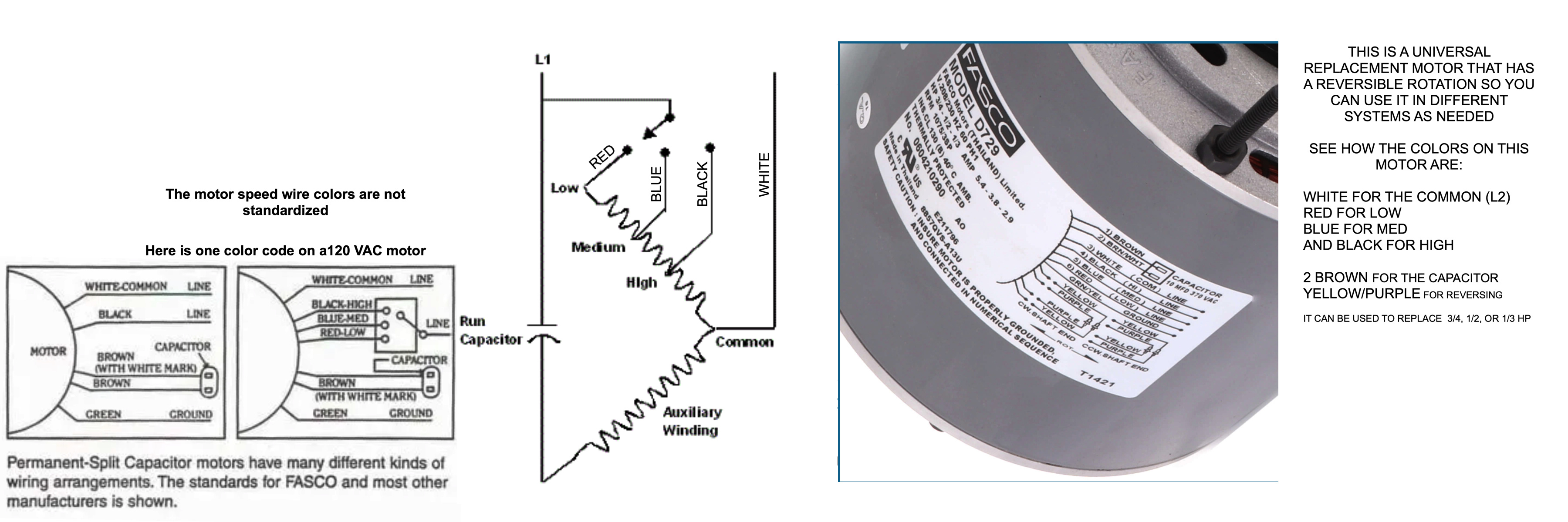
You may not have the original motor in this AHU. So don't use the motor colors I have on the diagram. Use the colors on the motor you have.
After taking a closer look, your motor may be FASCO or equal and it looks like the Red wire from the AHU is connected to the white wire on the motor and the black wire on the AHU is connected to the blue wire on the motor.
The red and black wires of the motor are capped off individually as they should be.
IMPORTANT:
You don't want to leave those wires hanging in the blower compartment. They are long enough to get sucked into the blower wheel. You will wantto trim them or at least bundle then up with wire zip-ties
Edward Young Retired
After you make that expensive repair and you still have the same problem, What will you check next?
0 -
it very much looks like the motor has been replaced
 3
3 -
Ah that hadn't even crossed my mind, that's why I was getting confused! Got it, I'll double check the wiring and make sure it's wired correctly. Yes those longer unused wires were previously zip-tied together, I had undone everything to make it easier to follow, but plan on tidying it up once complete.
0 -
Ok final question before I head down and work on the wiring, would you recommend I wire it with just 1 fan speed (medium) as your most recent diagram or should I wire it to have 2 speeds? If so, should I have low/medium/high for cooling or heating?
0 -
i'd probably try the second lowest for heating and fastest for cooling. there may be a chart on a lable in the air handler that gives speeds for cooling capacity or cfm pre speed, possibly with different esp. give it about 400 cfm per ton of cooling if it is rated that way, match it to the condenser if it is directly marked.
that vertical column of that chart might be cooling capacities with the 2 digit numbers cooling capacity in thousand btu/hr. i can't see all of it behind the wires
1 -
I found the wiring diagrams and charts for this handler online. I'll take better pictures of that chart/table too, thank you!!
0 -
Ok so got everything all hooked up and running!! Unfortunately, after 30 minutes or so I noticed that the system began to freeze up…😞
Filters were recently changed. I can check if the coils need to be cleaned, but I have a feeling that the refrigerant is low. It's a 5-ton York from 2003 with R-22, so not sure if it's worth, or even possible, to top it off for this summer and look into getting a new system next year.
2 steps forward, 1 step back
0 -
where is it freezing? is it just freezing the very bottom of the coil and the rest is warm or is the whole coil freezing and probably back in to the suction line?
1 -
The entire coil and back into the suction line was freezing. I also noticed that the air coming out of the registers felt cool, but not cold. So it likely was just circulating air that made it feel cooler, the temperature in the room did not actually lower based on the thermostat's reading.
0 -
what blower speed are you running for ac? is it turning in the right direction? It should be turning with the outer edges of the vanes in the blower wheel turning in to the direction of rotation. you may need to stick a phone inside the blower housing to take pictures of the label that shows which wires are which speed. looks like it might be missing a capacitor too.
1 -
if it were low on refrigerant you would get a few coils at the inlet freezing and the rest warm. you don't have enough airflow. did yo say there are zone dampers on this?
1 -
You could be running the motor in the wrong rotation. The blades should be scooping the air. You can change the rotation easily by switching the insulated factory connectors. They are the color pink. they are male x female so you can't mess it up.
1 -
You guys were exactly right and it seems as if the motor is not original and was replaced at some point. Seems to be a Century PSC motor model # F48SQ, RPM 1075/3, 3/4 HP, 5.5 amps
I connected it to the medium speed for now (was going to look into the cooling capacity/cfm speeds to see if I could optimize it later).
Based on the wiring diagram on the motor, that is the White and Blue wires (which were the 2 wires that someone previously connected to power.
I'll go turn the fan on and see what direction it's turning. I could also connect it to White and Black which is supposed to be high speed and see if that helps too.
Dampers are completely manually opened right now.
Is the arrow in the last picture the capacitor for the fan?


 0
0 -
yes, that is the capacitor. i couldn't see it in the rat's nest of wires.
try it on high and make sure it is the right direction.
1 -

Ok so blades seems to be spinning in the right direction. Just by looking at the blades, it seems to be "scooping" the air from underneath and sending it upwards which is what I would assume based on the layout of the ducts. In addition, the blades match the large yellow sticker on the blower that says rotation.
I'll try switching it to the high speed. Where should I be looking first for signs of freezing?
0 -
just look at it from time to time while it is running. you will first see patches of frost then they will get bigger as the frost restricts the airflow and the load on the coil falls further and the temp on the coil drops. not a terrible idea to check the current on the compressor and make sure it is at or below the nameplate rating too if you have a clamp on ammeter.
1 -
Wish I did, but unfortunately don't have a clamp on meter. Been running for 5 minutes, no sign of frost yet. Will go work on the the relay in my other air handler in the meantime and will check back in.
Hopefully that's all it needed! If that's the case, isn't it a little concerning that the "high speed" of this motor is the minimum required in order for it not to freeze up?
0 -
Typically the ac runs the blower at high speed. To some extent it will run correctly at whatever airflow the system was charged with.
1 -
Ah ok good to know. So far so good, no signs of freezing, thank you!!!
I thought I had read that running AC at a lower speed would help with dehumidification, but I guess that assumes that the lower speed provides enough air flow to begin with.
Guess I'll connect cooling to the highest speed and heating to medium. Thanks again!
0 -
Is that just a 3 speed motor? slowing down the airflow will drop the temp and dehumidify more but if you slow it down too much it will freeze. longer cycles at a lower capacity will increase dehumidification too
0 -
Hmm that's weird, my original post didn't get uploaded.
But yes, the motor is just 3 speeds, high/medium/low.So to achieve better dehumidification with longer cycles at lower capacity, if I like to have the bedroom thermostat at 72 degrees at night, would you recommend keeping the temperature just slightly above that during the day so it's constantly running (e.g. 76 degrees) or having the thermostat set to a higher temperature during the day (e.g. 82 degrees or higher) and only dropping the temp closer to bedtime?
0 -
The longer the compressor in the condensing unit (outdoor) operates the more condensation will be formed on the evaporator coil (indoor). So logically the lower you set the temperature for that zone, the morehumidity will be removed from the air in that zone.
If you choose a higher temperature during the day time, the evening temperature setting will not be reached for several hours, because the temperature can not drop from 82° to 72° until you remove enough humidity from the space to allow the temperature to drop. Depending on the amount of humidity in a space where the air conditioning system has been off for hours or even days as a result of a breakdown, or being unoccupied, that space may take as much as 24 hours of operating time before a 90°+ space will even get to the point where the thermometer will drop to 78° even if you set the thermostat to 72°. I have experienced this when summer residents return to the Jersey Shore vacation home and set the thermostat to 72° for the first time since the previous summer. The actual room temperature is 98° with 60% relative humidity at 3 o'clock in the afternoon on a hot summer afternoon. then i get a call at 5 o'clock saying the there thermostat is set at 72° for the last 2 hours and the temperature only went down to 95°.
"This is normal" I tell the customer "but if you want to pay for a service call I can come out to your home and tell you to wait until tomorrow and see if the AC is working. OR… you can just take this free advise and see if the AC is working tomorrow after all the humidity is removed from that house." It happens every year… at least 4 or 5 times around the middle of June.
@loamyroots11, Just leave the thermostat at 72° if that is the temperature you want to sleep with. That way there is a better chance that the bedroom will be 72° when it is time to go to bed. If 72° causes an excessive electric bill then you need to see if a higher temperature is comfortable for your family. You can try this experiment:
After installing my own central air conditioner in my own home, my wife and kids were very happy with the whole house comfort of central AC. I also used multiple air handlers with hydronic heat coils, so my system is very much like yours. I set the thermostats at 72° like most folks do. This was great until my wife received the first summer electric bill. Of course she wanted to know if there was something wrong with the new air conditioners because the electric bill was so high. I told her I would look into it. The nis set all the thermostats to 73° and left it there for a day. The next day I set all the thermostats to 74°, no complaints. I continued this process until I had the thermostats set at 79°. That is when my 14 year old daughter asked “Daddy, is there something wrong with the air conditioner in my room?”
The experiment was over… 78° there were no complaints, 79° there was a complaint. So I set all the thermostats to 78° for the entire home and everyone was happy, and the electric bill was much more reasonable. My electric usage dropped by about 18% with that 6° temperature change. Happy wife , Happy life! We all still use 78° for that home. My son lives there now, and has replaced all but one of those original AC units. That one is scheduled for next summer.
Edward Young Retired
After you make that expensive repair and you still have the same problem, What will you check next?
1 -
or if four reasons I to this day can not comprehend, you, like my parents, set the thermostat much higher at night and open the windows to let all the humidity in.
3 -
Nice love the anecdotes. In the past, we used to barely run our heat/AC to save money. But now with babies in the home, we've had to be more accommodating!
Just wanted to thank you all again for all your advice and help! The system is up and running, which is good timing as we're expected to have a heat wave this upcoming week.
0 -
Circling back as I started wiring up the Honeywell HZ322 zoning panel. I have the majority connected, except I'm getting confused in a couple of spots.
I'm having a hard time combining the HZ322 manual's diagram to the wiring diagram we previously laid out.
The zoning panel has separate R+C terminals for a dedicated 24V transformer. So I connected the zoning panel to its own separate 24V transformer that nothing else is connected to.
On the "Equipment" side of the panel, I connected "Rc" to the secondary 24 Vac wire coming off the RIB transformer (what Thermostat 6's R was previously connected to).
- Does the "Equipment" side of the panel not need a C terminal since it has a dedicated R+C to power the panel? If so, does it matter that I connected it to a separate 24V transformer or should I have connected it to the secondary wires of the RIB transformer?
- For heating, since W off the HZ322 is connected to the coil of the RIB24P heat relay, should I be connecting Rh on the "Equipment" side to the other side of the coil?
- In Honeywell's manual for hydronic water valve control, they have the dampers connected to Rh on the "Equipment" side and Th of the End Switch. My system is slightly different since we have a heat relay in place, but I'm wondering how do I go about wiring in the dampers?


 0
0 - Does the "Equipment" side of the panel not need a C terminal since it has a dedicated R+C to power the panel? If so, does it matter that I connected it to a separate 24V transformer or should I have connected it to the secondary wires of the RIB transformer?
-
There are several different applications that the HZ322 can be used. I believe the optional diagram you selected is a design to operate three hydronic zone valves. That diagram has nothing to do with duct work dampers. In our previous discussions posted back on June 7, the idea was to operate damper motors for duct work that was using a circulator pump to send heated water to one duct coil in one AHU and sending that heat (or cooling in the summer) into two different zones of duct work. The diagram you selected does not do that.
Just follow the normal zone damper wiring, the hydronic side is already taken care of in the air handler unit

Depending on the damper motor you have the M1, M4, and M6 terminals may be wired differently.
Edward Young Retired
After you make that expensive repair and you still have the same problem, What will you check next?
0 -
Ah ok, so Rh and C are not needed on the panel’s equipment side, thank you!!
1 -
Most people run there AC at too low a temperature. 76-78 is usually comfortable unless you in a location with severe humidity.
Its important the AC units are not oversized. They have to run a long cycle to control humidity. Oversized units drop the sensible heat (thermometer) and cycle off and the humidity is too high and you feel warm at 70 deg.
1


Categories
- All Categories
- 87.6K THE MAIN WALL
- 3.3K A-C, Heat Pumps & Refrigeration
- 59 Biomass
- 429 Carbon Monoxide Awareness
- 124 Chimneys & Flues
- 2.2K Domestic Hot Water
- 5.9K Gas Heating
- 119 Geothermal
- 168 Indoor-Air Quality
- 3.8K Oil Heating
- 78 Pipe Deterioration
- 1K Plumbing
- 6.6K Radiant Heating
- 394 Solar
- 16K Strictly Steam
- 3.5K Thermostats and Controls
- 56 Water Quality
- 51 Industry Classes
- 50 Job Opportunities
- 18 Recall Announcements