Confused by basement runs in school 2 pipe system

I have been helping manage facilities at a small school and recently started investigating the steam heat for the building.
Heating the building (about 10000 sf) has been expensive to the point where the teachers are running electric space heaters in place of using the central steam boiler and convectors. I'm eventually trying to figure out our medium-investment options for improving the comfort of the building (including changes in air sealing, better ventilation, and central boiler). For now, I am just in the stage of understanding how the whole thing is put together and how it was intended to work. I'd love some help with that, especially when I'm trying to understand how the basement heat is working.
Boiler pictures are first. I took one picture from the control side.
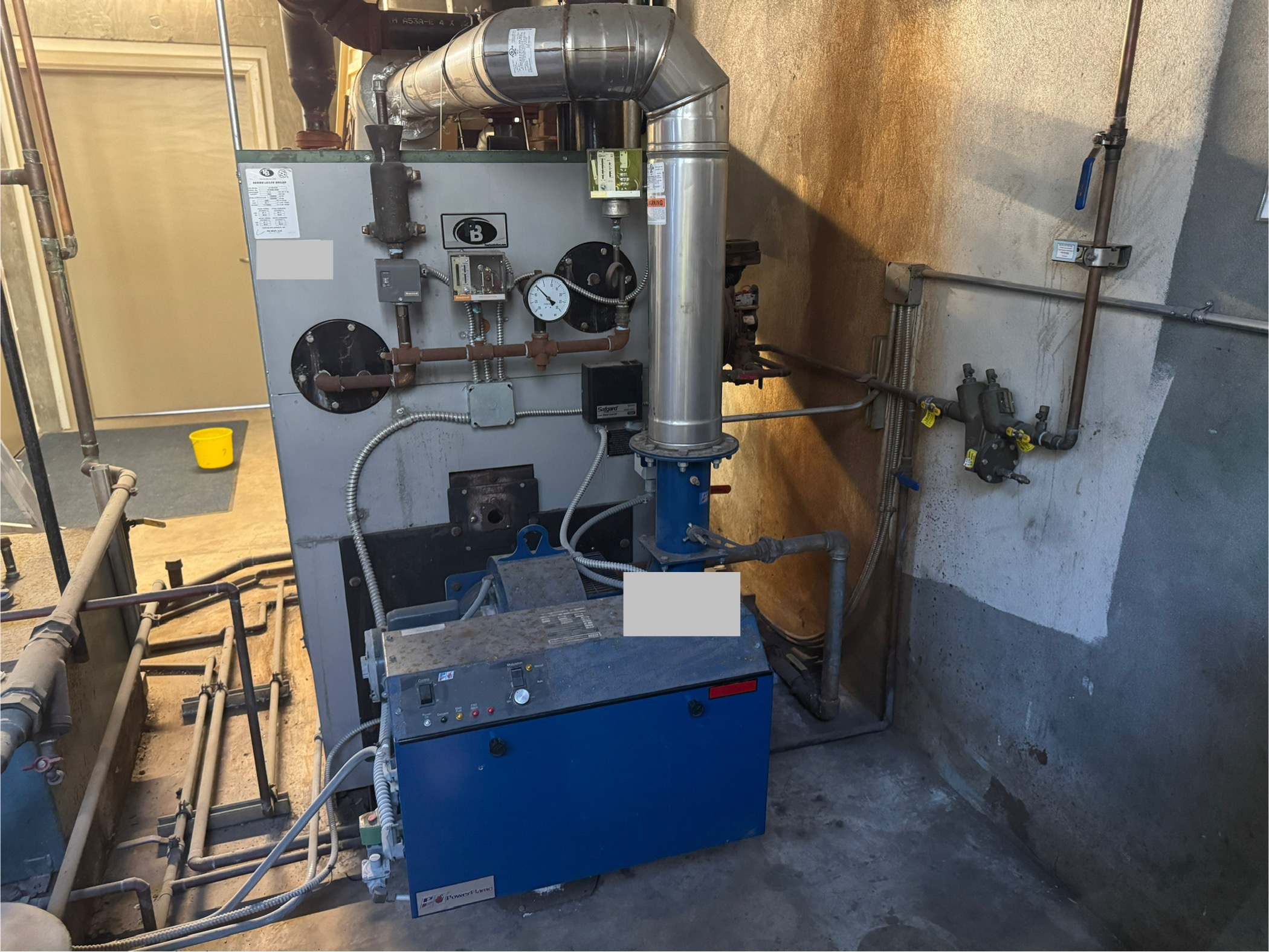
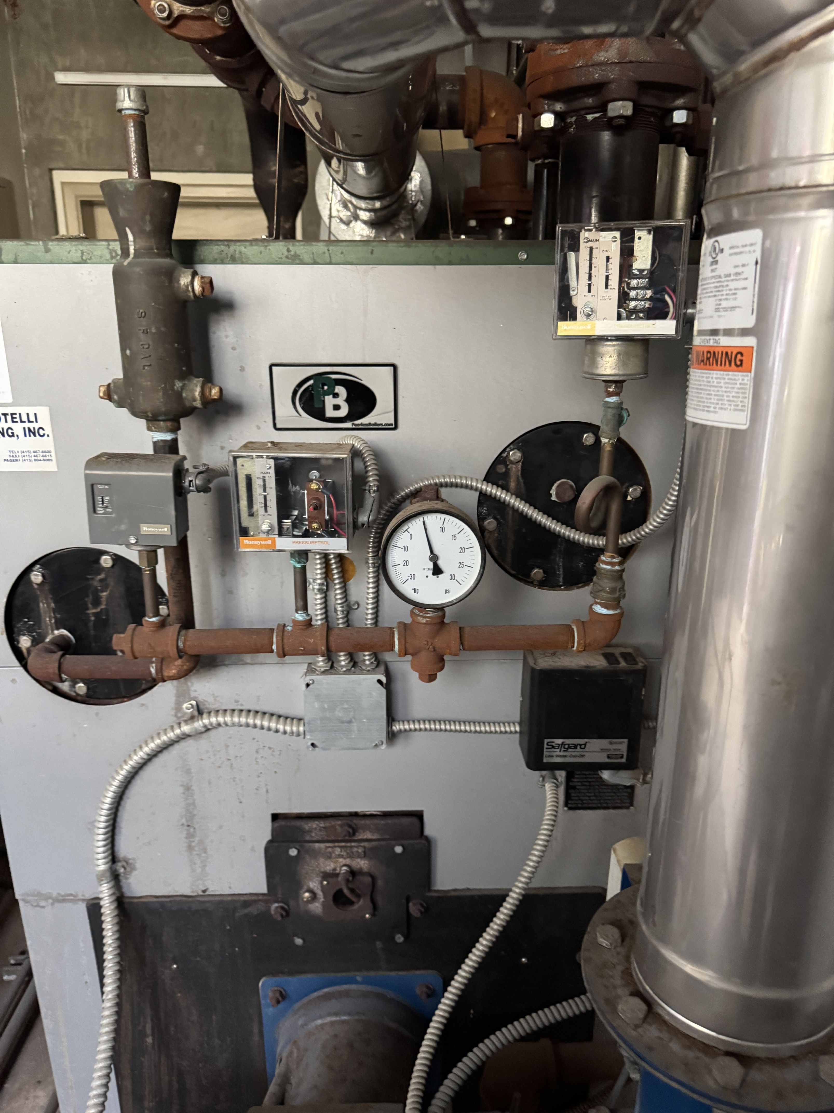
And zoomed in on the controls. I see the shutoff pressuretrol, the -30 to 30 PSI gauge, and the operational pressuretrol (It looks to me like a L91B?). The Safgard LWCO is below.
Against the wall (no good picture) are a LWCO/autofill valve and some other control I haven't identified yet.
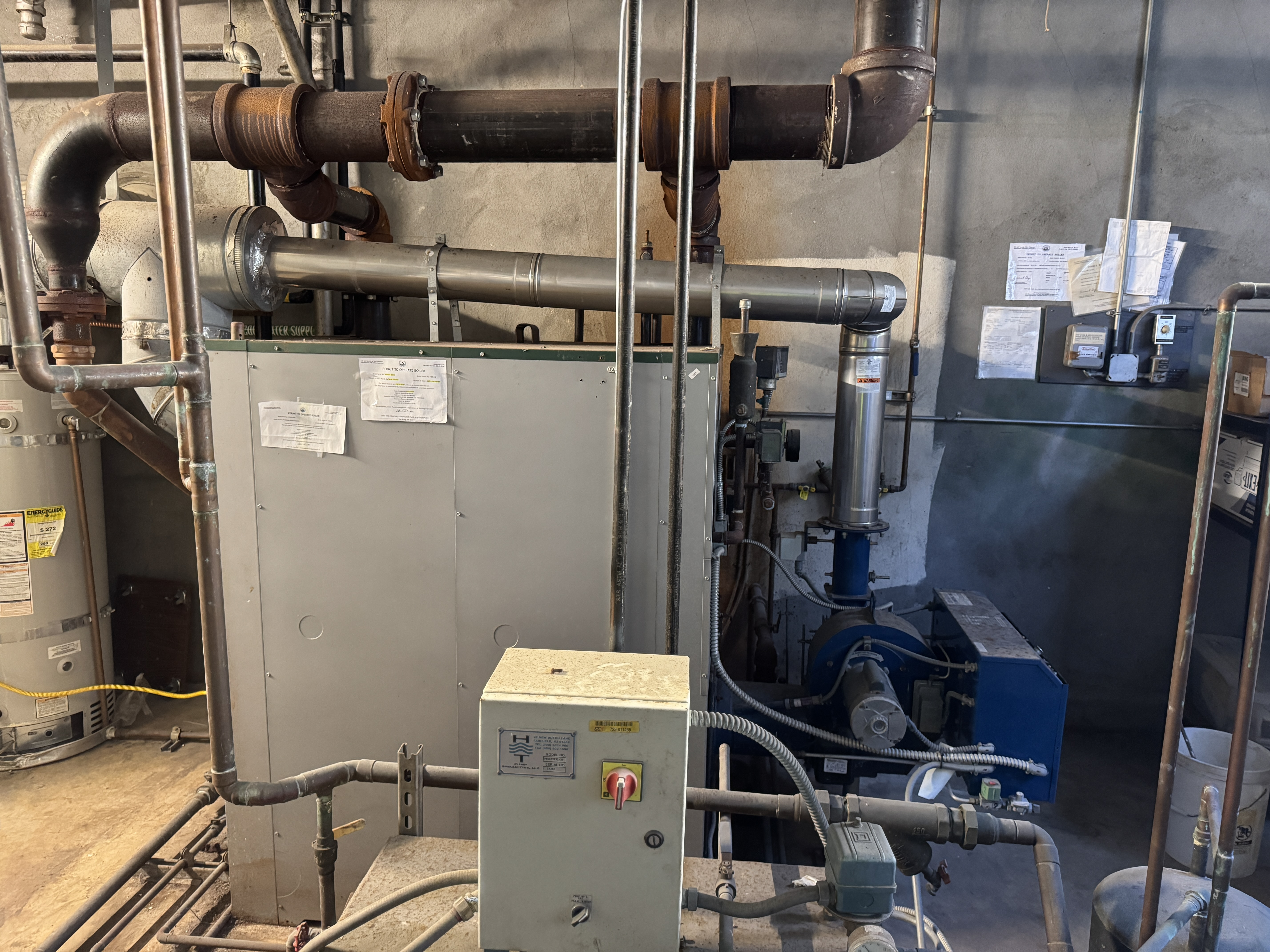
View from another side. I just realized I missed the mains in this picture. I'll go re-take this picture when I get back to the site. The steam main goes up another 24" or so before breaking off 2 main lines that go left and up to the ceiling of the room with some sort of condensate return coming back.
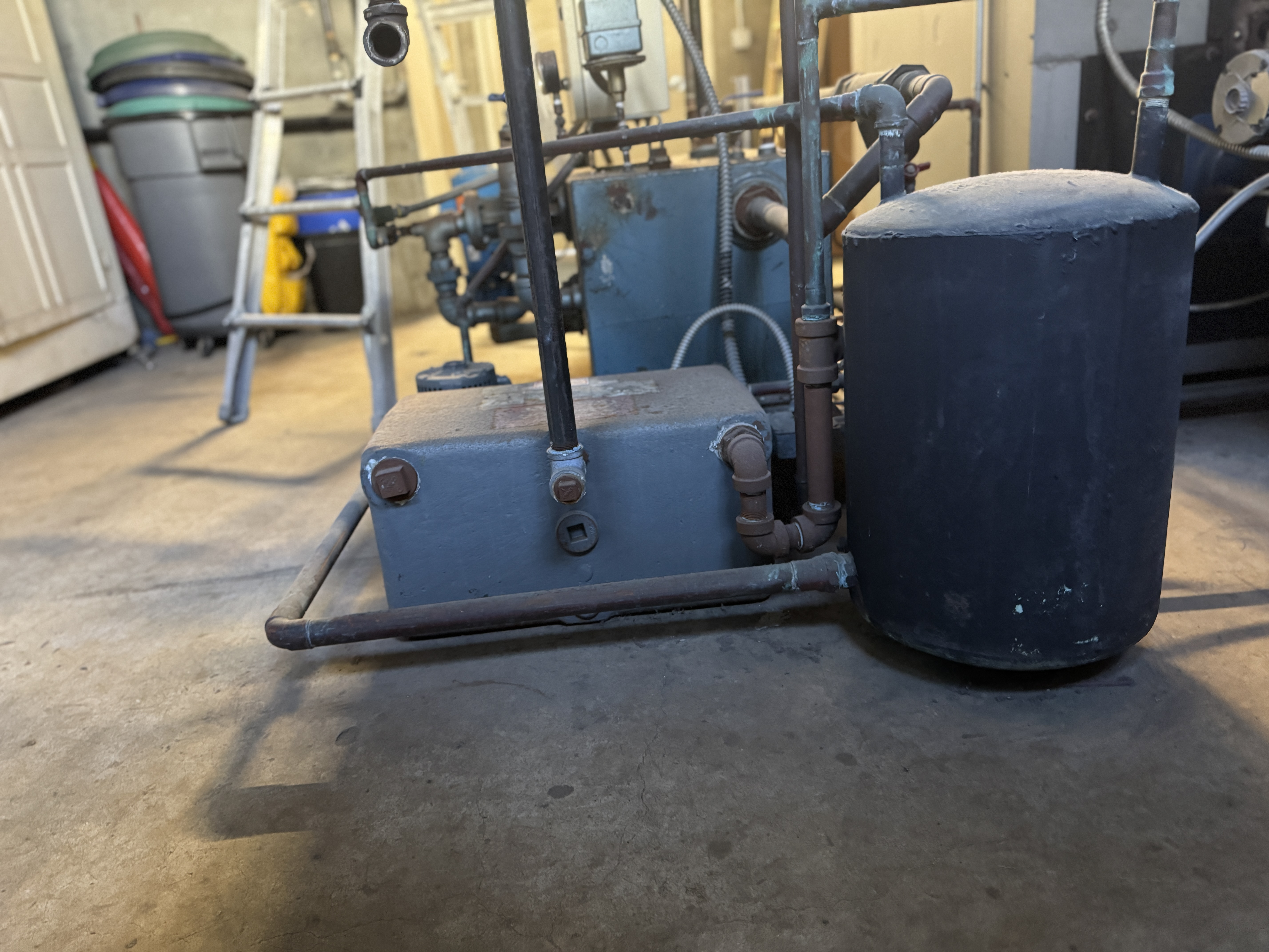
In front, I have what I assume is a receiver and recirculation pump. Better pictures here:

The mains look like they are heading up to convectors in the top 2 floors of the building (there are 3 stories, including the conditioned basement level that has a big auditorium).
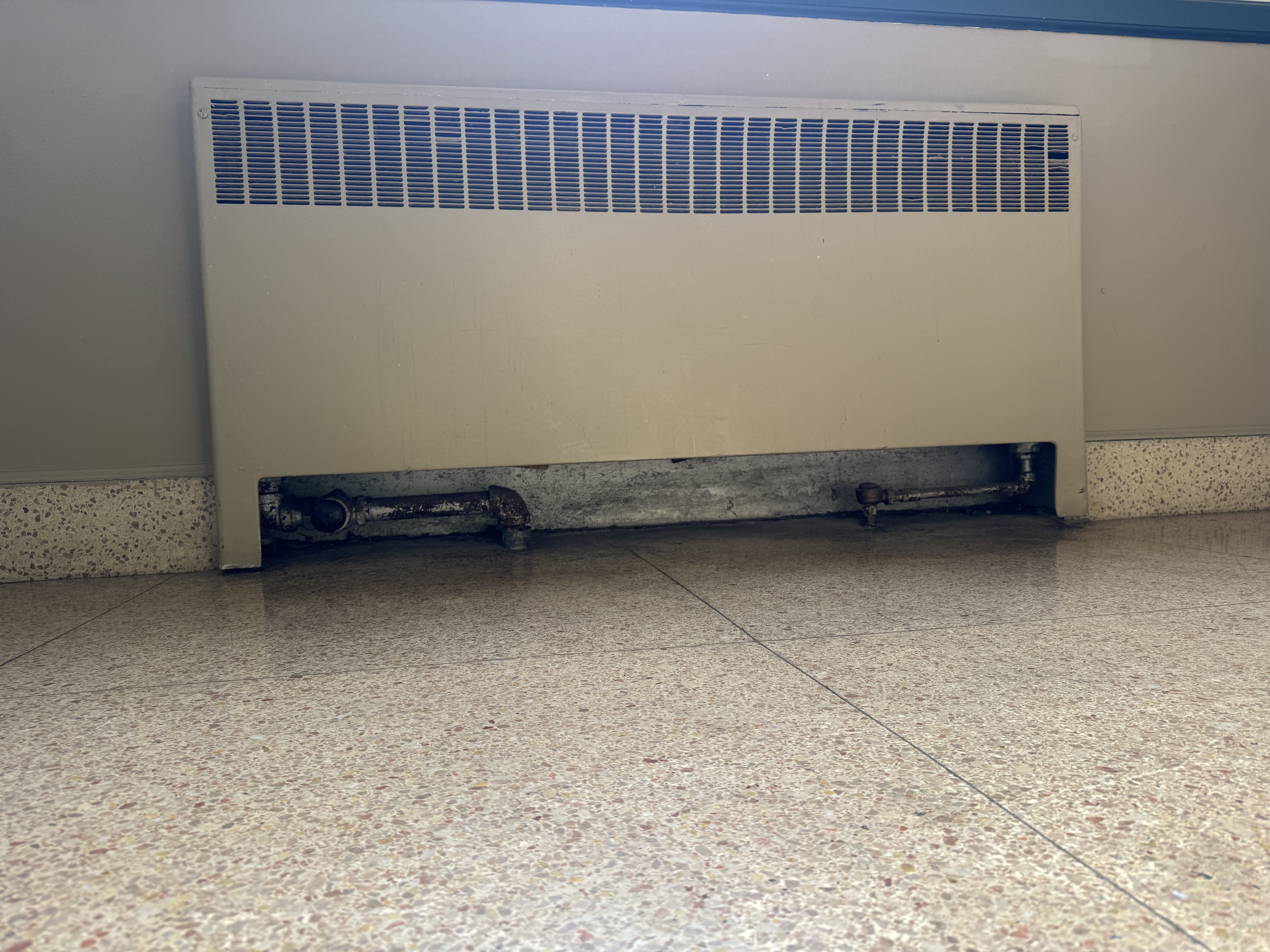
An example convector in an upper/main level of the building. This portion of the heating system is not terribly mysterious. Some of the steam traps seem to be broken (both sides at 212 F, but otherwise this seems like a fairly standard setup.
The return lines for the upper levels look like they are going to a standard dry return that is > 10 ft above the boiler's water level. This descends into the receiver and condensate pump assembly. I took pictures of the parts, but I don't understand the condensate system in full yet.
The part that is particularly confusing is the heating for the basement level. The same style convector are used, including the steam traps below the boiler & condensate pump. The returns for these convectors are then piped up to what I thought was the dry return for the upper portion of the building.
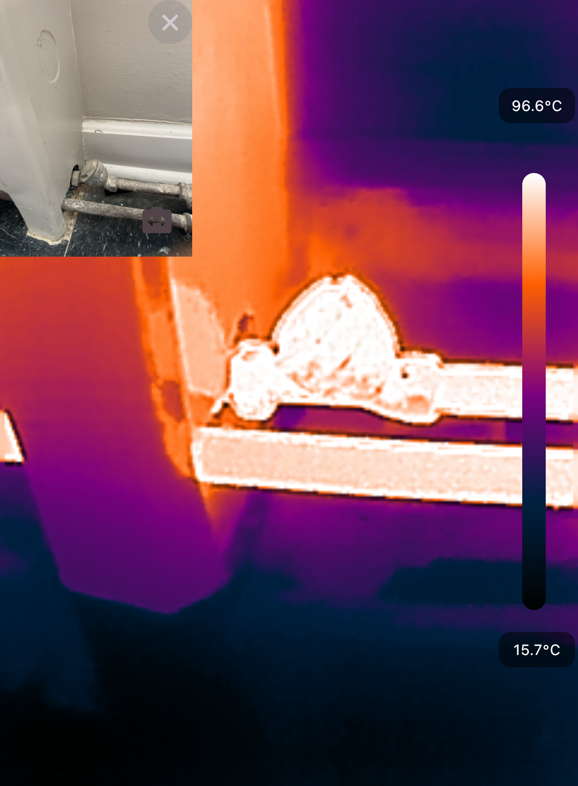
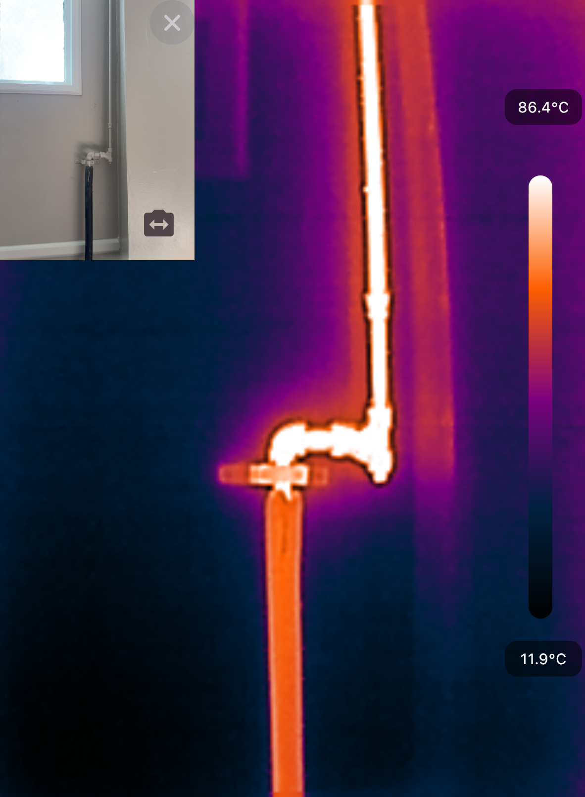
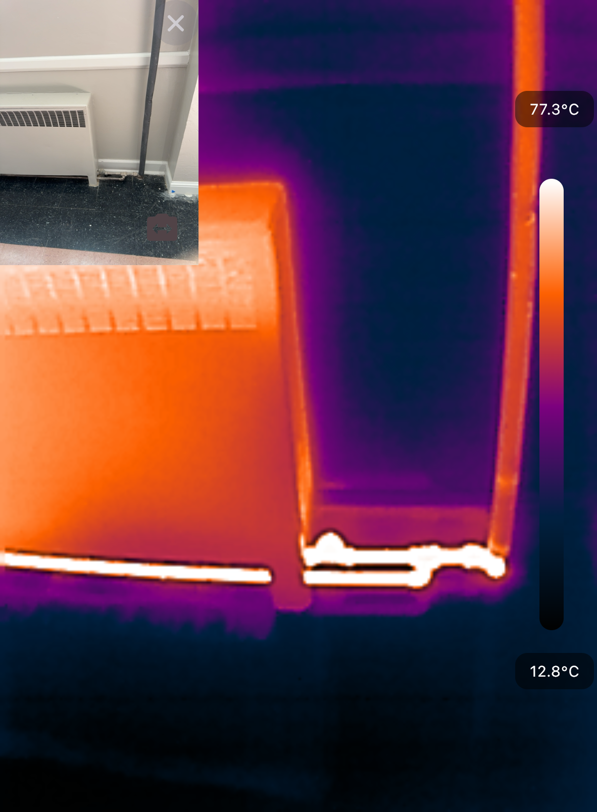
I took a picture of the return lines coming out of one convector with my thermal camera. To the right of this, the return line goes almost straight up to the previously described (dry?) return line that sits about 15 ft above the floor (about 11-12 ft above the boiler water level)
My first question: how should this basement system be working? Based on the discussions I've read on this site, I expected to find the top two levels of the building operating with steam and the basement level to be heated with a hydronic loop. What I see here, there are steam traps and plumbing in parallel with the radiators above. The convectors appears to get hot, but possibly just with condensate?
I see a similar design in a few of the staircases (with the return ascending 8 ft above the convector and source steam pipe). In one case, I found what appeared to be a disconnected, abandoned return that was below the convector in a crawlspace.
Other little mysteries I haven't figured out yet.
Short-cycling I am trying to understand:
- The boiler has very short cycles. The flame is on for 2-3 minutes, then off for 2-3 minutes for hours on end. The thermostat (a vintage round thermostat that sits in a drafty hallway) never reaches its setpoint so it isn't cycling on that. The pressuretrol looks like an L91B modulating control, maybe that is triggering the cycling?
- The pressure never deviates far from 5 PSI during operation. The boiler pressure takes 15 minutes to drop from 5 PSI to 3 PSI after I shut off the power. I'm not sure if that means I am or am not cycling on pressure.
- There is surging in the sightglass, about 3 inches up and down.
- Any hints on where to look? I'm not sure how to tune the pressuretrol I have. Maybe something is wrong with how it is adjusted?
- I don't see the actuators modulating the input much, just flame high or flame off.
Thermostat setup I am trying to understand:
- The thermostat is a line-voltage thermostat. It controls power to the entire boiler control system (e.g. when the thermostat is below temperature, the boiler control system has power, when the thermostat is above setpoint, the whole thing is unpowered). I am not sure if that is normal, but it seems kind of weird?
At this point, I mostly want to understand what I'm looking at so I can read the right books and posts in this site to do basic maintenance until our next annual maintenance visit, when I will have the time and budget to ask them more questions. Ideally I can get this system into shape enough that we can run it more regularly. We use space heaters instead of the central heat whenever possible because it is so expensive to run the steam.
The obvious things I think I should be trying to do to get more heat into the conditioned space for less $$$:
- Cleaning the convectors: the most obvious fix I've found. The fins in the convectors are caked in dust. Getting them cleaned off seems like it should help.
- Clean the boiler: I need to learn to skim the boiler and perform a blowdown regularly. The water in the sightglass goes surges noticeably. Nowhere near the top or bottom, but 3 inches from top to bottom. The water is also tinged red. I skimmed the boiler with very low water flow until the resulting water no longer retained bubbles when I mixed it up, but haven't seen an impact on the surging.
- Steam trap maintenance: I think I've found 2 steam traps in the building that are broken (> 95 C before and after the trap, no temperature drop). I probably won't DIY rebuilding them, but fixing them should reduce waste. I fear breaking the piping, especially near the finished floor, so I'll wait until we can afford a professional.
- Lower the pressure: everything I see from Dan Halohan says to run at 2 PSI or lower. Assuming the basement heating can still function at low pressure, I should be trying to lower the setpoint on the pressuretrol. I'm pretty confused by the pressurtrol right now though, I need to understand that unit better.
- Add a low-pressure gauge: I'd like to have an additional gauge on a pigtail that can give me a more precise reading < 5 PSI if I can get to lowering the pressure.
- Insulate: a small portion of the mains in the boiler room are insulated with some nice classic asbestos. Very few of the returns throughout the building are insulated. I'm not sure what the payoff for insulation is since most of the returns are in conditioned space and most of the mains are inaccessible, but some nice fiberglass insulation can't hurt the efficiency, at least.
Anyway, thanks for reading this.
Please let me know if I'm on the right track for understanding the system and in particular if you have ideas about how all of this works (or where to look for more clues). While it isn't as old as a lot of the systems I read about here, it still feels like a bit of time travel. Trying to understand the folks who put this all together.
Comments
-
- the steam in the returns will kill the pumps in the condensate/feed tanks. Not sure why there are both. Not sure whoever put the last boiler in knew what they were doing either but pumped returns is a little above my head.
- I am not sure how the basement is set up. Is there a pipe below the floor for condensate and a pipe up to the return for vent or just a pipe up? If there is just a pipe up it might need the 5psig to lift the condensate. If it isn't lifting condensate then the pressure probably can be much lower.
- If it is short cycling on pressure either the system isn't consuming the steam that is produced (likely because the air can't get out because your returns are full of steam) or the burner should be modulating or dropping to low fire.
- Figure out what is wrong and what needs to be fixed before adding insulation. Insulation will just make figuring out how it is piped and is supposed to work and making any changes harder.
 2
2 -
Show the t-stat please, If it is the old standard round those were usually 24 volt.
Take off the outer ring and look for a slide adjustment called a heat anticipator.
Set it for longer run time, that may be why you are short cycling.
Having both a condensate pump and a feeder pump sitting at the same level is unusual. A condensate pump just pumps when it is full to a certain level…..I assume it pumps into the larger feeder pump tank. And boiler level controls call the feed pump as needed to top off the boiler.
There could be several reasons for the short cycling besides the t-stat.
You may have a LWCO that is late in starting the boiler feed pump…..or the pump supplies too much water too fast and jiggles the water level to where it shuts the boiler down.
And it looks like if you have condensate lift devices for the basement convectors.
Show good close up of all 3 pressure controls you have there.
I had a similar school building with issues and it took a fair amount of time and money to correct 30 years of neglect…..so tell us more.
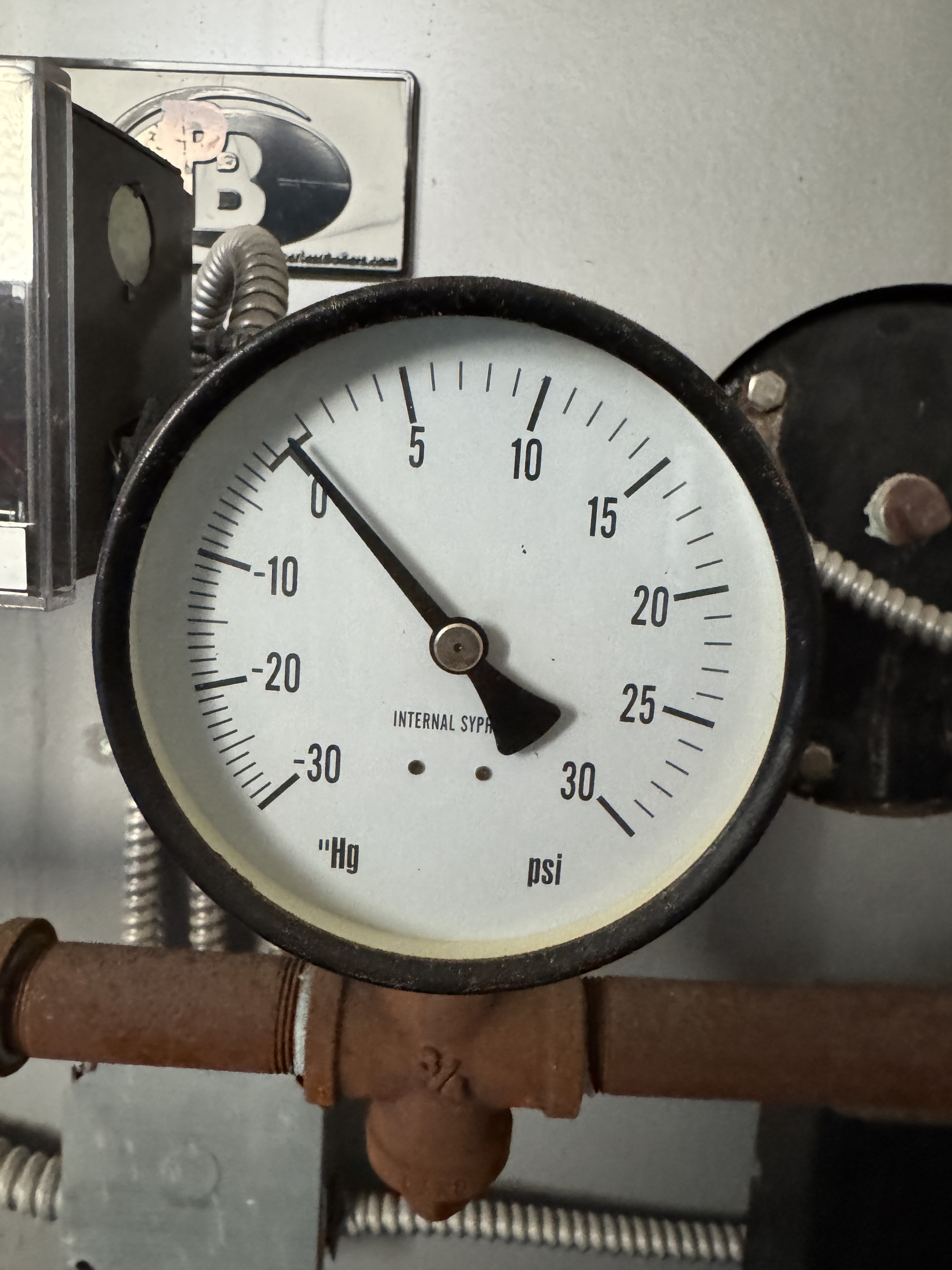
Also, when off and almost cold does the pressure gauge go to zero?
2 -
The pressure control on the left the PA404A is the operating pressure control
The middle control is a Manual reset high limit….it should be set higher than the PA404A it is a back up if that control fails.
The control on the right is a L91 A or B it does not start or stop the burner it only controls low-high fire
1 -
I'm almost certain this was designed as a Vacuum system, where a vacuum pump would draw the condensate up from those basement convectors and would also help pull air from the entire system. The receiver/pump with the box sitting on top is likely some sort of vacuum pump. @Pumpguy is our resident vacuum expert, hopefully he will see this.
All Steamed Up, Inc.
Towson, MD, USA
Steam, Vapor & Hot-Water Heating Specialists
Oil & Gas Burner Service
Consulting 3
3 -
Quick word of thanks to everyone who responded already. You all are great. I will get some better pictures when I get back on site tomorrow.
Re: PA404A. I see. This makes more sense. I misinterpreted that component. Thanks! I’ll read up on that one since it has the more standard differential settings available.
I think I made a mistake when describing the thermostat. I’ll get a picture of that too. It is definitely not the standard round one at 24V.
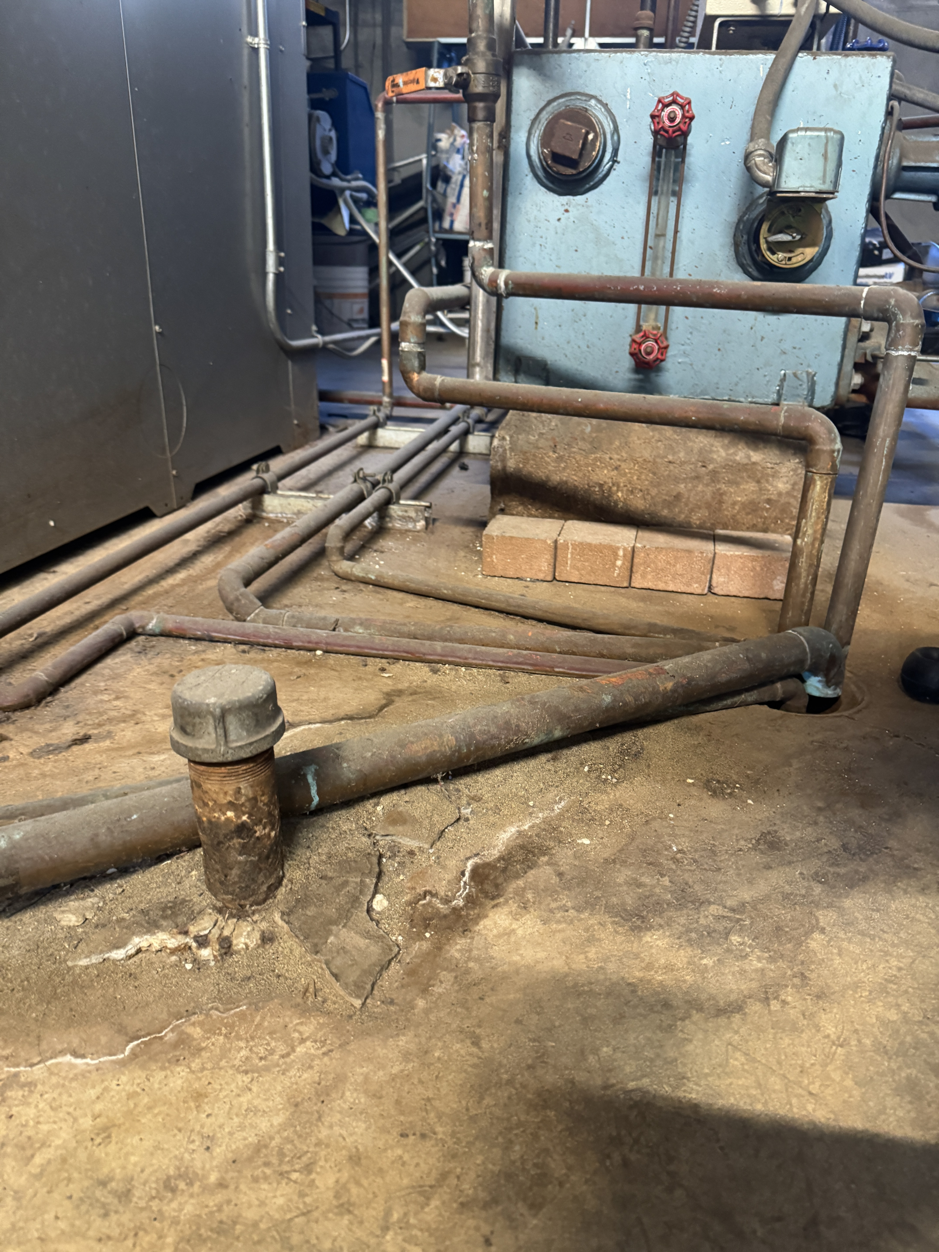
Re: piping: I can’t find any piping that currently goes under the floor in the basement. It looks like there used to be something coming out, but whatever it was is filled with concrete and cut off at floor level. I will try to get a picture of that too.
I will focus on getting pictures of all the control mechanisms I can find and make an inventory list so it’s easier to read for you all.
Re: T-stat. I am pretty sure it has nothing to do with the thermostat. I tried setting it to 90 degrees and I still saw the short-cycling.
thanks again!0 -
Could be the pipes under the floor were leaking and were retrofitted somehow.
0 -
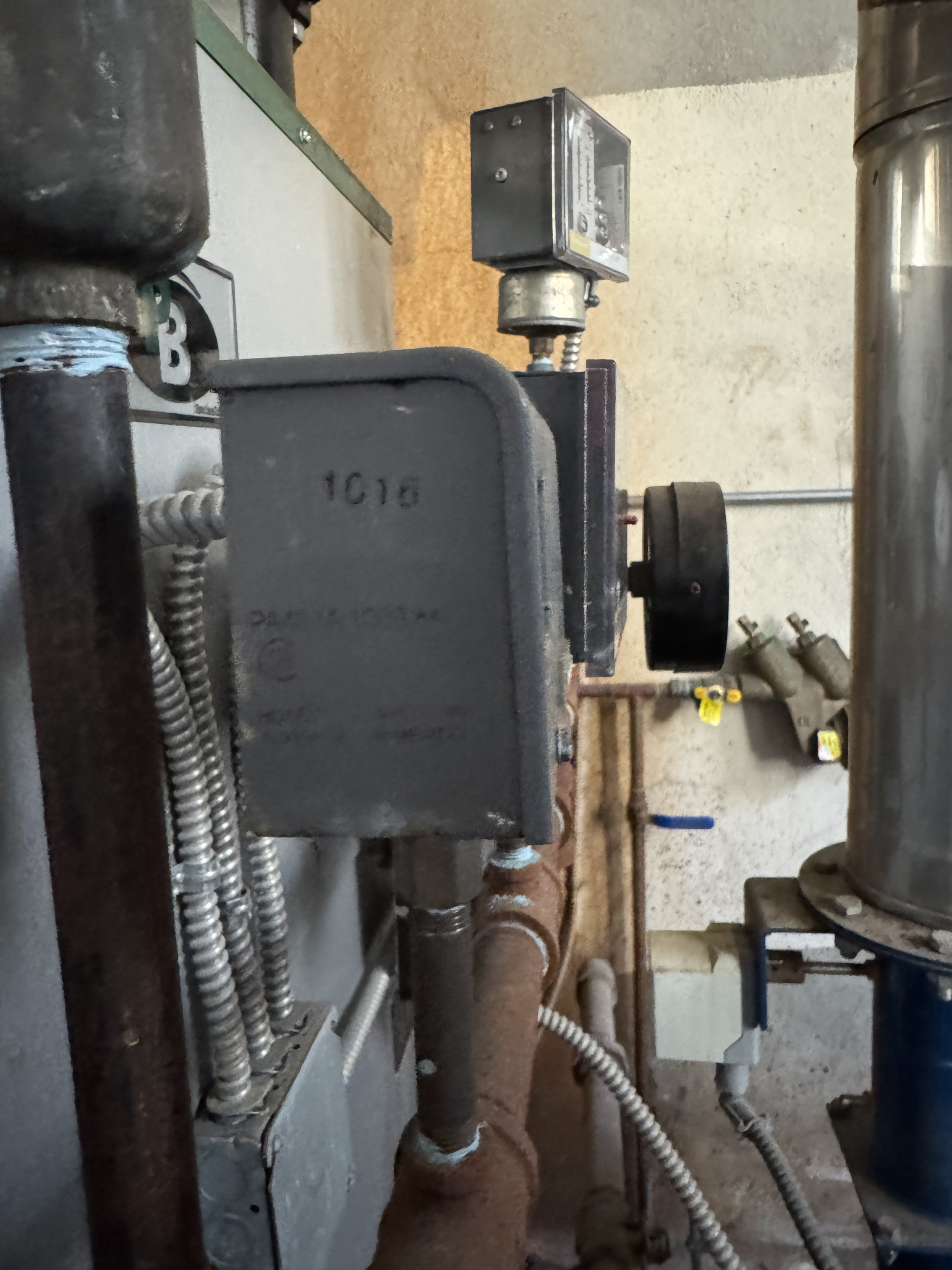
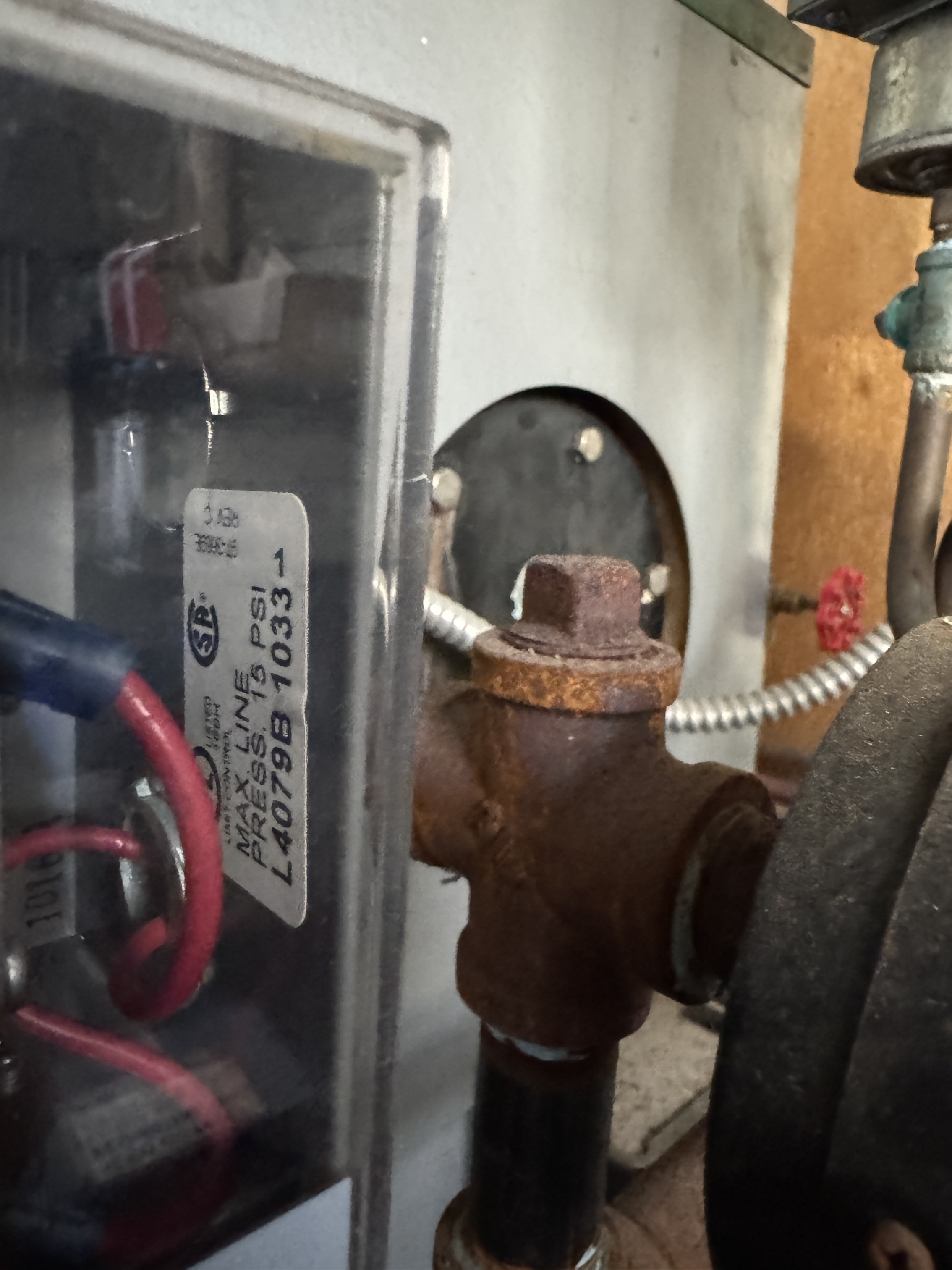
Posting some more pictures of the control portions. Starting off with the controls mounted on the boiler.
As @EBEBRATT-Ed mentioned. This is a PA404A controlling the flame.
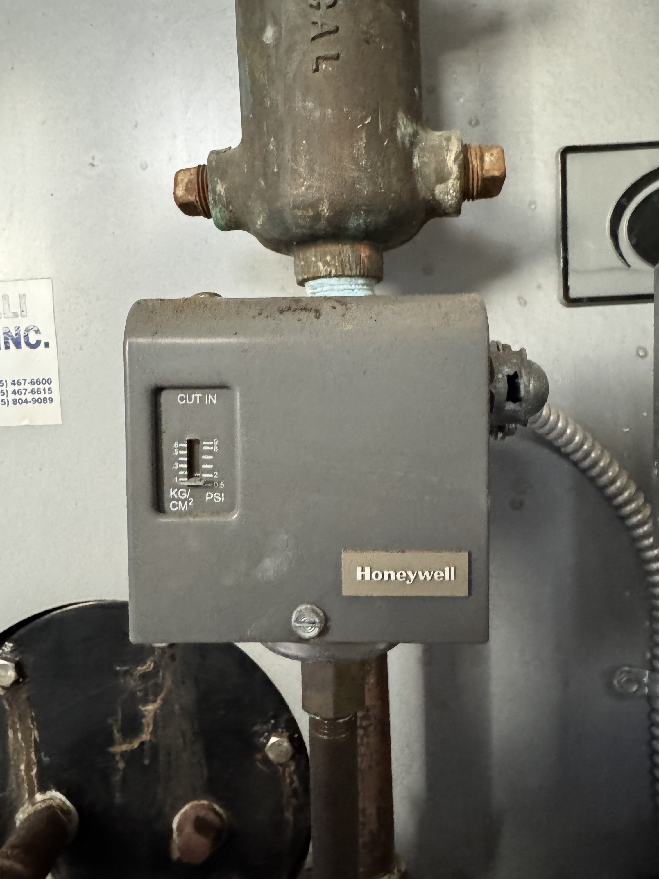
And here is the safety shutoff pressuretrol.
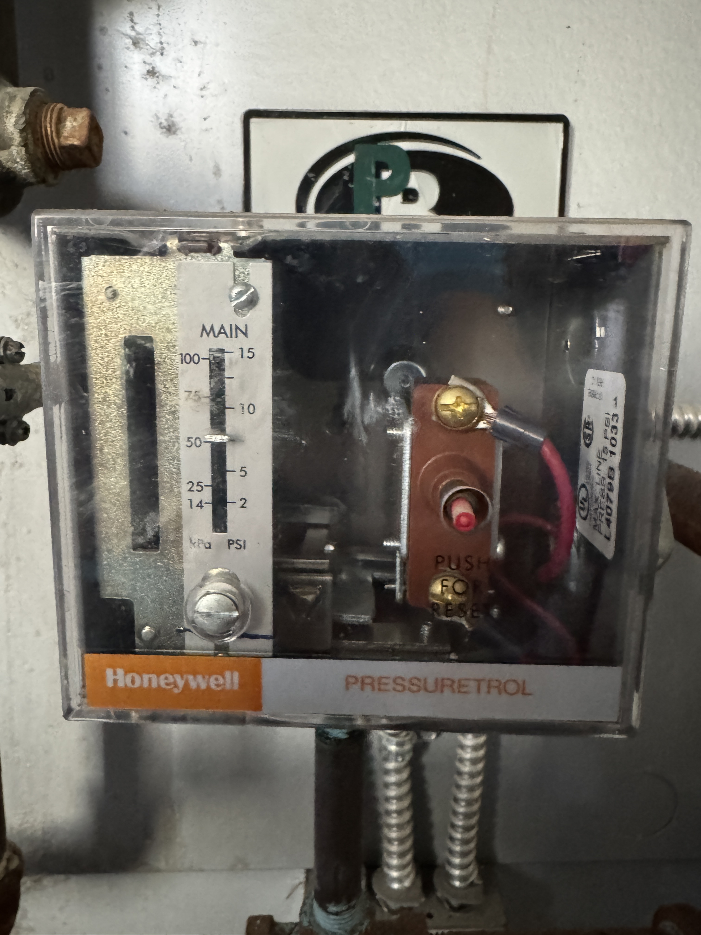

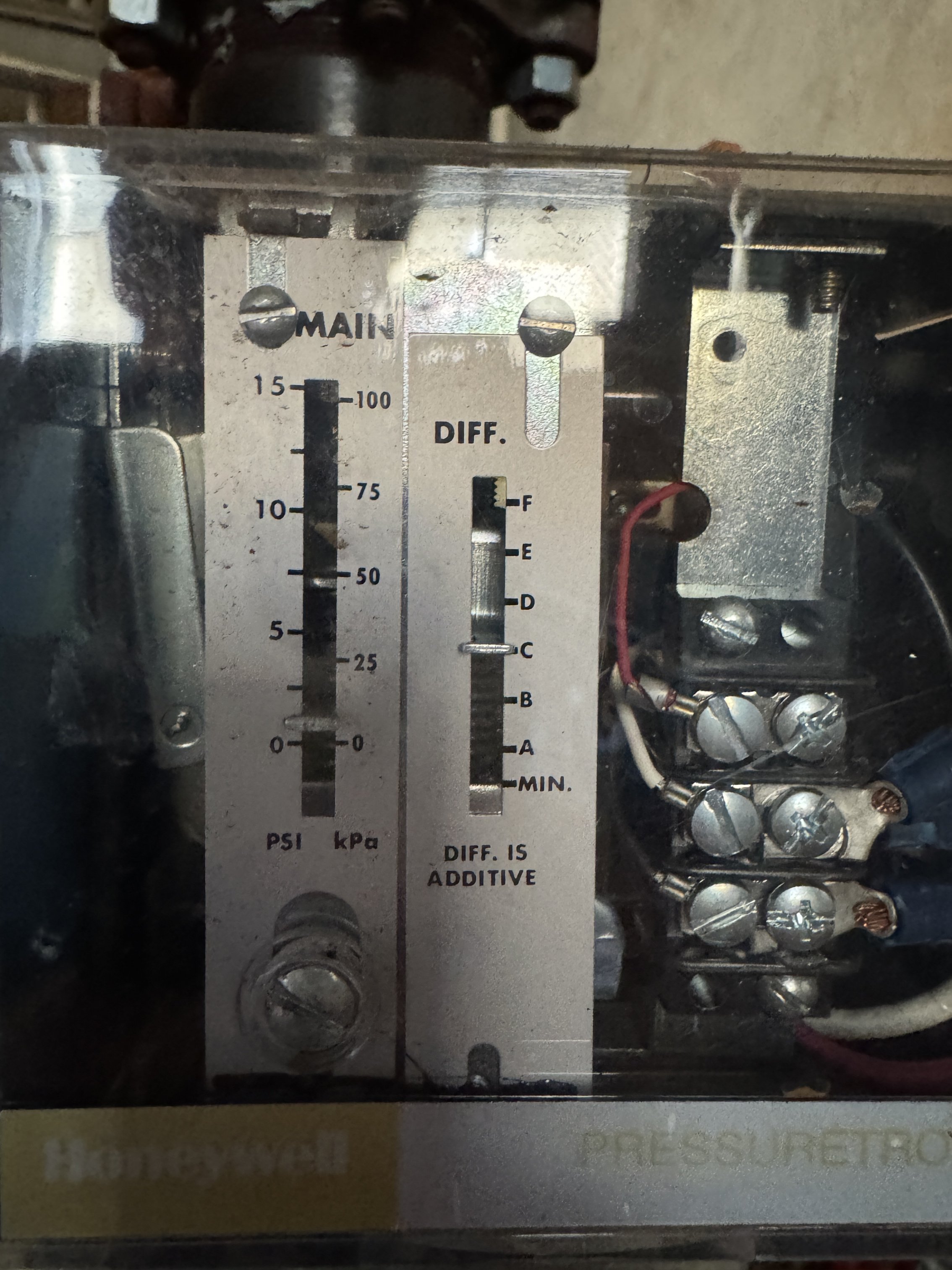
And here is the modulating pressuretrol.
And just for completeness, the pressure gauge. It goes to
Show the t-stat please, If it is the old standard round those were usually 24 volt.Here is the thermostat with the cover off. It's not the old standard round, it's something else entirely.
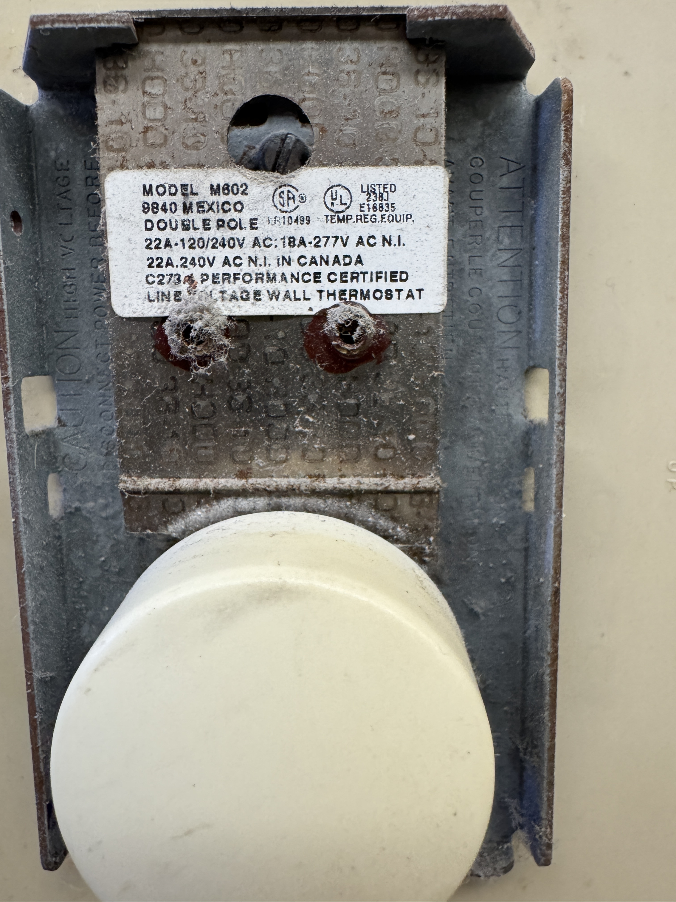
When the temperature is above setpoint, the entire boiler control assembly is unpowered (no 120V power, no power light, nothing). When the temperature is below setpoint, the entire boiler control assembly is powered. This seems like a really odd setup to me, right?
Answering some more questions:
@JUGHNE, there is for sure no pipe below the floor. Something is lifting the condensate. Based on @Steamhead and looking more closely, it looks like the big receiver/pump is a vacuum pump that is sitting at the end of the condensate lines and also has a path to the the steam mains. I'll try to diagram what I'm seeing. If it was a vacuum system originally, it seems like steam trap failure damaging the vacuum pump would make sense. Someone fixing it by increasing the pressure is also described in a few places around here:
I will be reading this, but it looks even more like I need to audit all the steam traps first before I even think about the health of the vacuum portion of the system.
You may have a LWCO that is late in starting the boiler feed pump…..or the pump supplies too much water too fast and jiggles the water level to where it shuts the boiler down.@JUGHNE I'm trying to figure out if it's this. Is there a trick to figuring out if the LWCO is implicated? I'm not sure how to tell which control is shutting it off, maybe I just need to monitor each device with a multimeter?And it looks like if you have condensate lift devices for the basement convectors.Yeah, agreed.
Show good close up of all 3 pressure controls you have there.See above. Any other controls?
I had a similar school building with issues and it took a fair amount of time and money to correct 30 years of neglect…..so tell us more.I imagine that's what I'm dealing with here.
Also, when off and almost cold does the pressure gauge go to zero?Yes, for sure. It takes 30 minutes to get to zero, but it ends up exactly at 0 (picture above). Does that match your expectation for cooldown time?
Here are some more closeups of what I think is the vacuum receiver, pump, and control:
Top view
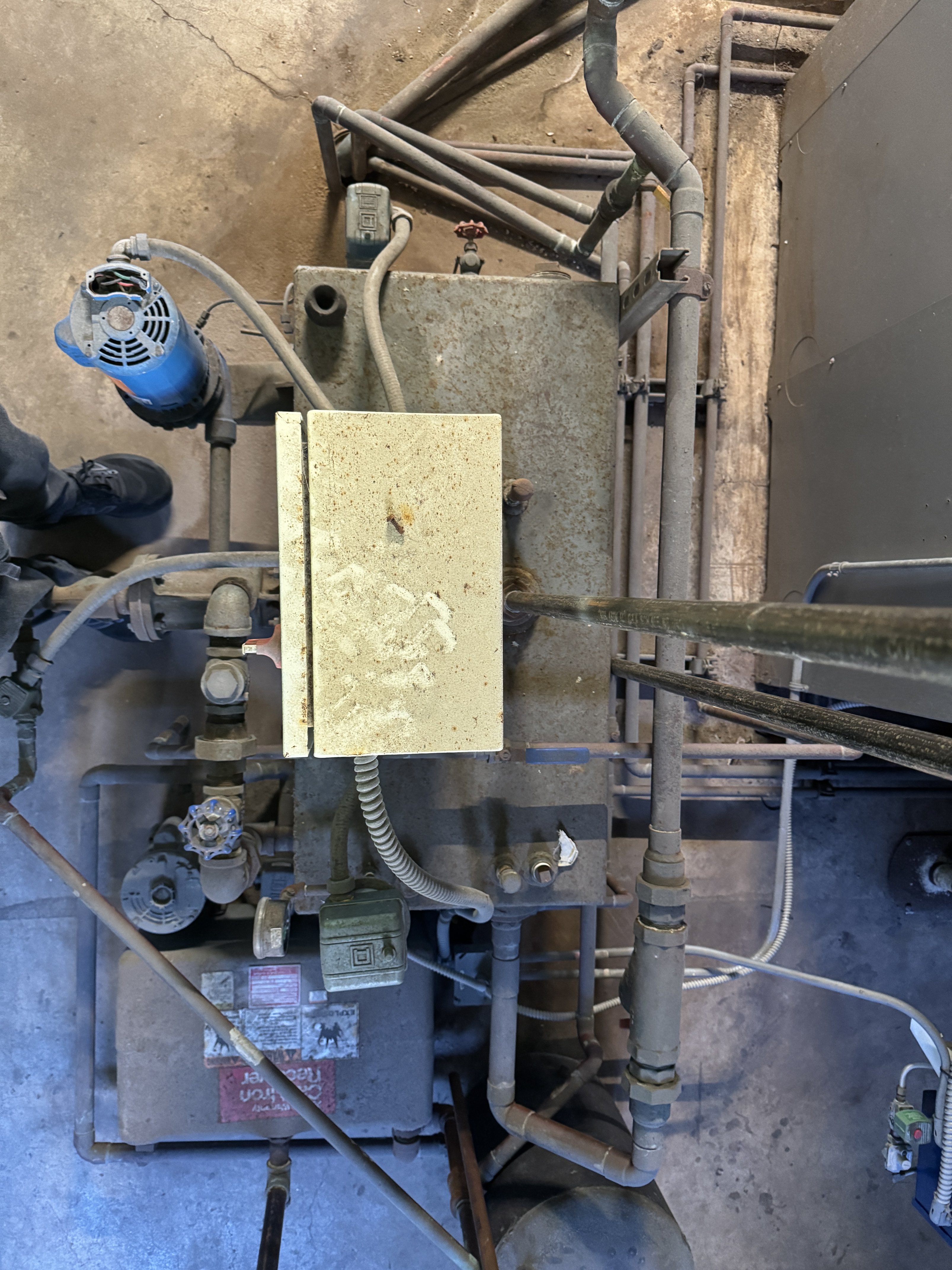
Sight glass on the side of the vacuum receiver (top side in the picture above).
Close-up of what I guess is the the vacuum pump motor on front of vacuum receiver (blue motor on left side of top view).
Close-ups of the box on top of the vacuum receiver. I'm going to try opening this thing up to see what is actually inside. Maybe there is something more identifiable.
Please do continue to send your theories or questions.
0 -
That thermostat looks like a line voltage electric heat thermostat. It is probably powering the boiler control circuit. That is indeed an unusual way of controlling a large building like that; it was probably the cheapest solution at the time when the original controls, perhaps something like a heat timer, failed.
—
Bburd1 -
There is a pipe coming up near the floor drain that may have been the wet return for the basement system.
My best guess is that when this boiler was changed a few years ago the vacuum pump was installed. There may have been no pumps at all before that.
If this was the case, it is surprising that the leaking UG wet return was addressed as it is outside the boiler and often neglected at a change out.
The school I mentioned, that this reminds me of, did locate their blueprints from the 1950's. Somewhere in your building there may be a copy of prints, hopefully no one pitched them away. Schools seldom throw anything away. One school I work on has a "Print Vault" mounted in a hollow wall. Just a 4" chrome plated cap showing, the tube is at least 36" long.
Prints might show where end of main (EOM) F&T's are located, probably above a ceiling. May have drawings of the vacuum system, if original to the building.
Where is this school located?? You (they) need someone fluent in vacuum systems.
Only a few here might be familiar with the vacuum pumps and I am not one of them.
Your short cycles might have something to do with the hi/low control. It reaches a certain pressure and should switch over to low fire but something not connected and it shuts down. The burner control panel may have a manual switch for low/high fire.
2 -
i also noticed the capped pipe out of the floor that @JUGHNE mentioned and thought it was an abandoned return. depending on the age of the building the original boiler could have been coal and that explains the makeshift boiler control. looks like a standard line voltage t-stat with maybe the knob replaced with a security cap.
1 -
Location is in San Francisco. There don’t seem to be very many steam experts out here, especially on this site (closest is a few hours away, closer to LA).
I might need to find out who maintains the systems in the old buildings in the downtown area.0 -
In SF your heat requirements are a lot less than in say MA. You just need a little bit of heat on the colder days so the one t-stat for the whole building is probably fine. It is weird that it is line voltage but there is nothing wrong with ding it that way, just harder to wire.
1 -
Vacuum pump? Hoo boy, where to start?
How is upstream return line piping configured? Is the purpose of the vacuum pump to lift condensate and compensate for the abandoned buried returns?
If the answer is yes, I need to see and know all details of the uphill return line piping.
If the answer is no, then all return lines must allow a gravity down hill flow of condensate into the vacuum pump's receiving tank.
Dennis Pataki. Former Service Manager and Heating Pump Product Manager for Nash Engineering Company. Phone: 1-888 853 9963
Website: www.nashjenningspumps.com
The first step in solving any problem is TO IDENTIFY THE PROBLEM.2 -
Not 100% sure but it looks very much like the returns are going straight up from the emitters.
0 -
It looks like there is a separate Hoffman condensate pump near the vacuum pump?
Pictures of nameplates of both pumps, not the motors but the unit tag itself, this might help Pump Guy figure this.
Is there an overhead steam line for the basement? The supply drops look to be dripped into the return line before it goes back up to the ceiling. Are there 2 traps at each emitter?
0 -
I suspect there are 2 emitters next to each other piped in to one riser.
0 -
Returns going straight up from the emitters? That shouldn't be.
Can we see pictures of heat emitter outlets and up flow return lines?
Dennis Pataki. Former Service Manager and Heating Pump Product Manager for Nash Engineering Company. Phone: 1-888 853 9963
Website: www.nashjenningspumps.com
The first step in solving any problem is TO IDENTIFY THE PROBLEM.0 -
look at the tiny thumbnails in the ir pictures, looks like there is a steam trap and an ell then the return goes up.
0 -
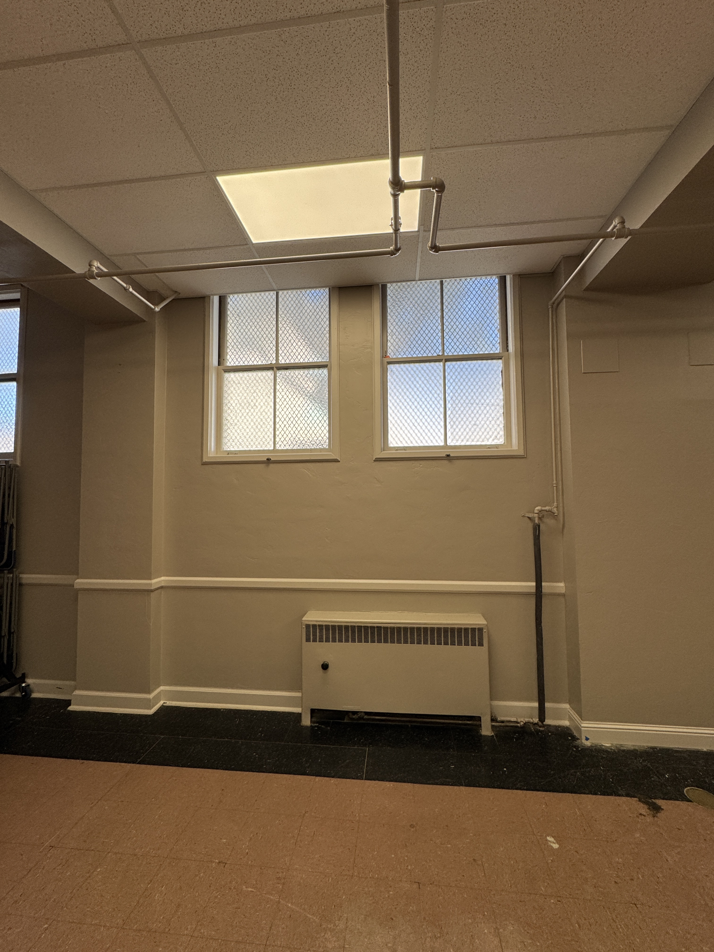
here is what the emitter looks like in the basement. The source comes from the wall. The return goes up into the pipe near the ceiling. I think there is a steam trap right after the emitter, then it goes up. The pipe near the ceiling is the same return as the upstairs units pipe to.
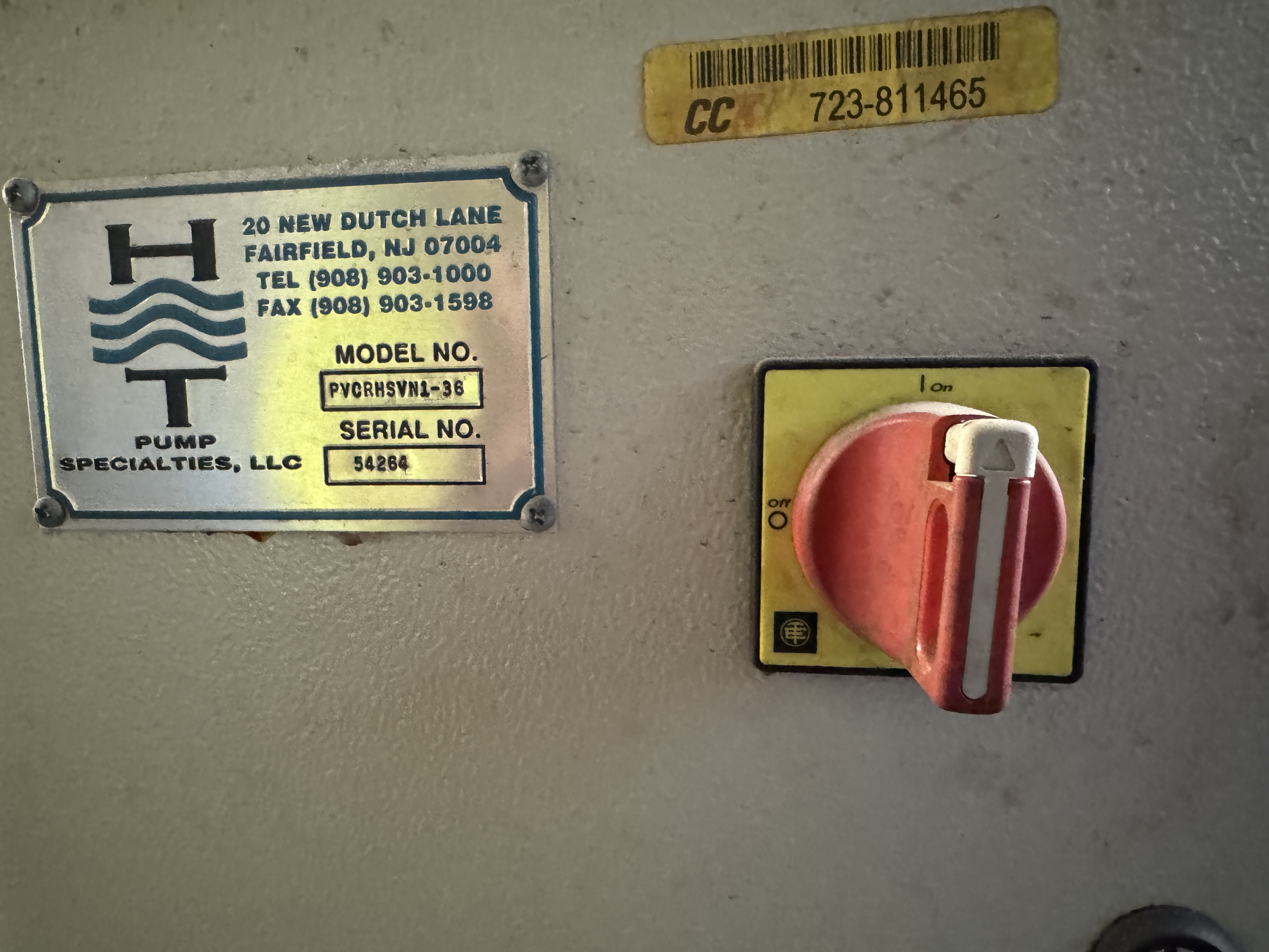
The nameplate for the condensate pump (the smaller one) was visible after some cleaning.
I couldn’t find anything resembling a nameplate on the vacuum assembly, the best I have is the front of that control box.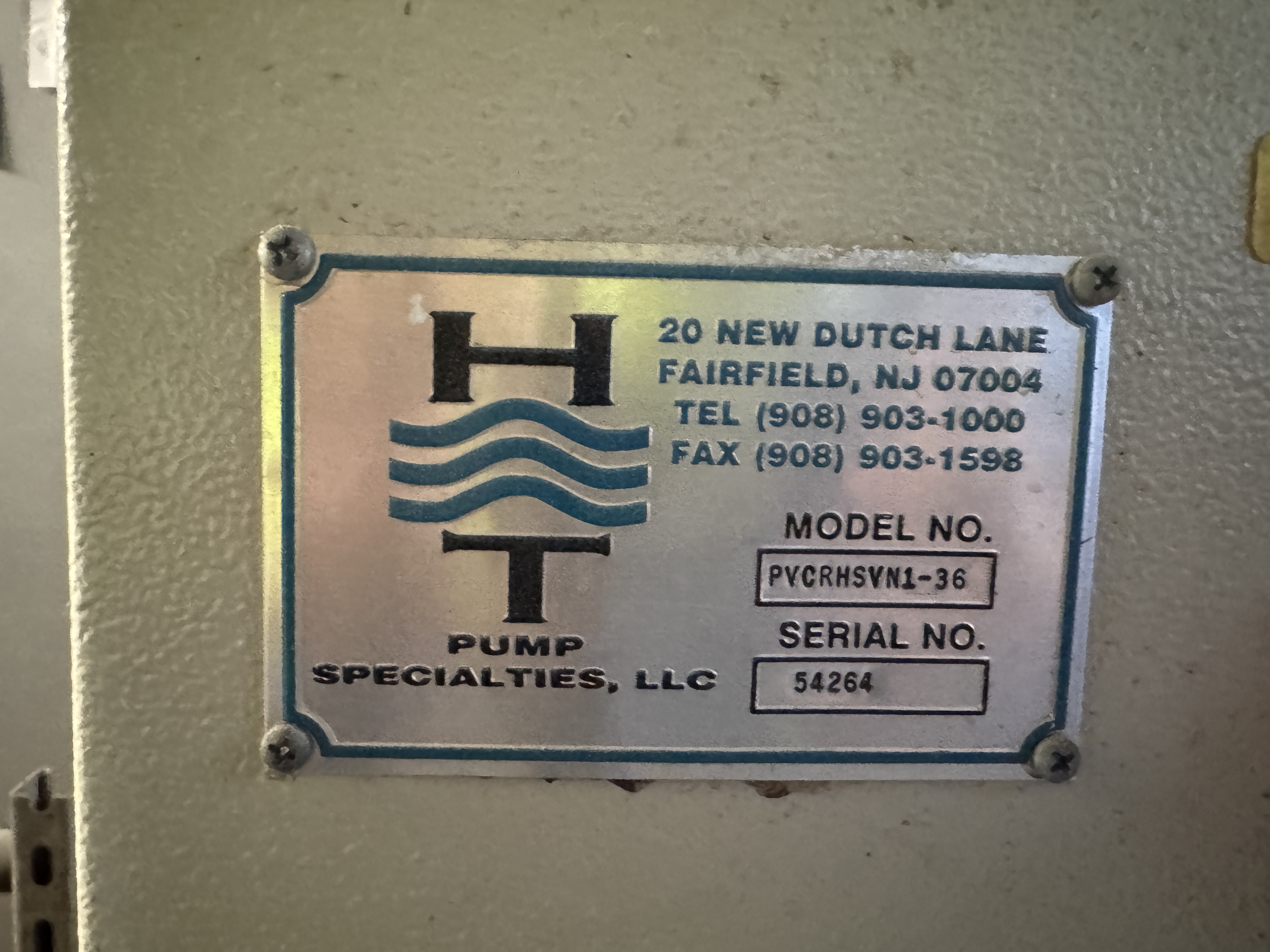 0
0 -
I’m sure a few round trip plane tickets would help in finding experts!😇
 3
3 -
isn't @Alan (California Radiant) Forbes in that area? he isn't necessarily the biggest steam expert but he is good at asking questions and reasoning things out.
1 -
A few mysteries resolved this morning. I was able to confirm that it is a vacuum pump. It pumps down to -1 or -2 PSI regularly, waits, then pumps down the pressure again. That part is starting to make sense to me now. I’m still looking for the blueprints since that will help immensely and stop wasting the time of you kind folks.
The other mystery I resolved was the lack of modulation. If you look at the L91 pressuretrol in my pictures, you’ll see that someone tied the red and white wires together on the white terminal. This seems to mean that the controller will always see too low of pressure, effectively disabling the modulation.
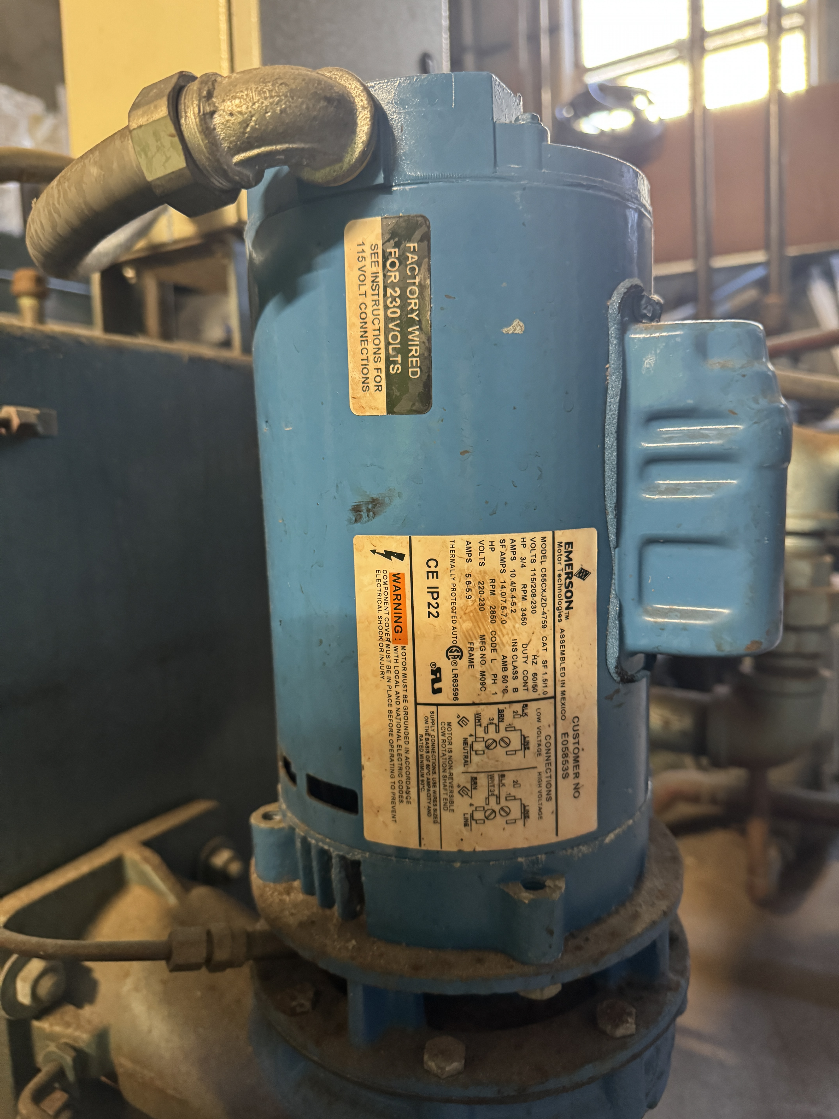
I also found the nameplate for the pump. It was hidden underneath. This is the pump that is running while the vacuum receiver gauge drops to -1 to -2 PSI.
There is still a lot to learn, but I think I have a basic picture now! I will need to find a vacuum expert, some fixes for the control system, and some replacement steam trap cartridges, but I can see those next steps at least.
Thanks all!0 -
Hmmm…. Water doesn't flow uphill on its own, so we need a higher pressure on the outlet of the heat emitter than there is in the up flow pipe and the overhead return line to move the condensate out of the heat emitter. And if we can't get rid of the condensate, we can't get steam in.
The rule here is Fluids are Gasses and Liquids, and ALL FLUIDS FLOW FROM HIGH PRESSURE TO LOW PRESSURE, ALWAYS.
From the outlet of the heat emitter to the overhead return line is, what, 10 feet? Let's say it is 10 feet which means we need at least 10 feet of water column pressure differential to move the condensate.
The pressure gauge on the vacuum pump is calibrated in INCHES OF MERCURY, (In Hg.), not PSI, and not in inches or feet of Water Column. (In. H2O or In. WC). In rough terms, inches of Mercury and feet of water are the same pressure, and one PSI equals around 2 inches of Mercury.
So, that means with a single step lift, we need a 10" Hg. vacuum on the overhead return line to make the lift.
It appears the uphill return line piping is arranged in a 2 step lift, but the needed change in pipe size doesn't appear to be there.
The attached file goes into detail about the piping requirements for vacuum lifts. Even for a 2 step lift, the total amount of lift shouldn't exceed 8 feet.
Keep in mind that in order for a vacuum lift to function, the needed pressure differential always needs to be present, which means the vacuum pump must run continuously. Turn the vacuum pump off and we loose the pressure differential and the low level condensate just sits there, and no steam can get into the heat emitter.
The recommended way to handle high condensate lifts is with a separate condensate tank and pump set to serve as a mechanical lift. The attached file has the details.
The important concerns here is the condensate pump's receiving tank must be air tight, and suitable for operation in a vacuum. The other concern here is this receiving tank must be vented to the overhead vacuum return line using the arrangement shown, and not just to atmosphere.
Considering the condensate outlet from the heat emitter is right at floor level, we're not going to get a nice gravity drain of the condensate into the condensate pump's receiver tank. You could try putting a check valve on the outlet of each radiator trap and raise the return line slightly. Another solution would be to raise the heat emitters enough so their outlet traps are high enough so the condensate gravity flows into the condensate tank.
And now for the vacuum pump itself. The pictures don't clearly show what type of vacuum producer is on this unit, but I suspect it is of the water jet type where water is pumped through a venturi nozzle to produce the vacuum.
In any event, a quick and dirty way to check what the vacuum pump can do is to valve off its receiving tank from the rest of the system and then turn on the vacuum pump to see how much vacuum it can make on a closed off tank. You should see around 20" Hg. showing on the gauge so long as the condensate is around 150*F. or lower. High temperature condensate can reduce the maximum vacuum that can be achieved.
Unfortunately, this test doesn't tell us what volume (CFM) the vacuum pump is moving. To determine the CFM, you can consult the vacuum pump manufacturer's tables. Typically a water jet type vacuum pump will move between 6 and 10 CFM per motor horsepower.
If you really want to know the CFM, you can perform an orifice test. The attached file shows the details. Don't let this scare you, it's really quite simple. Once you know the orifice size and the resulting vacuum, get back to me with these numbers and I can look at my tables and tell you what the CFM is.
Dennis Pataki. Former Service Manager and Heating Pump Product Manager for Nash Engineering Company. Phone: 1-888 853 9963
Website: www.nashjenningspumps.com
The first step in solving any problem is TO IDENTIFY THE PROBLEM. 3
3 -
Hey Dennis, your information is priceless! Never saw it in one place before!
0 -
Yes. This is extremely helpful. I did not think of it as slugs of water going through the pipes. I was imagining a filled water column going up. This makes more sense how a low vacuum could expect to get the condensate 10+ feet above the convector without running a 5 PSI pressure differential.
These are the last convectors to heat up in the building. Failure to follow the design guidelines may be preventing venting and condensate evacuation.I will let you know if I can find some blueprints. I bet the original design won’t have those verticals.
0 -
Yes, in a 2 pipe system like this, the return lines have to handle both condensate AND air. The presence of either will prevent steam from entering the emitter.
Dennis Pataki. Former Service Manager and Heating Pump Product Manager for Nash Engineering Company. Phone: 1-888 853 9963
Website: www.nashjenningspumps.com
The first step in solving any problem is TO IDENTIFY THE PROBLEM.1 -
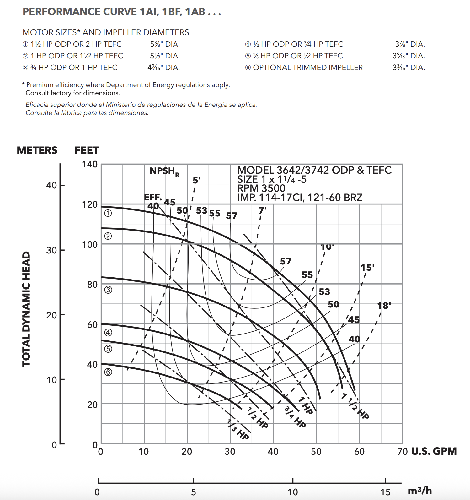
Haven't done my own tests to make sure, but I got my hands on the manufacturer's lookup chart. The vacuum pump is the Gould 1 BF 10712. This has 3/4 HP.
If I look at this curve and assume I am running at < 10 PSI head (23 feet), then I read that as 45 GPM or about 7 cfm. That seems to line up with your expectations.
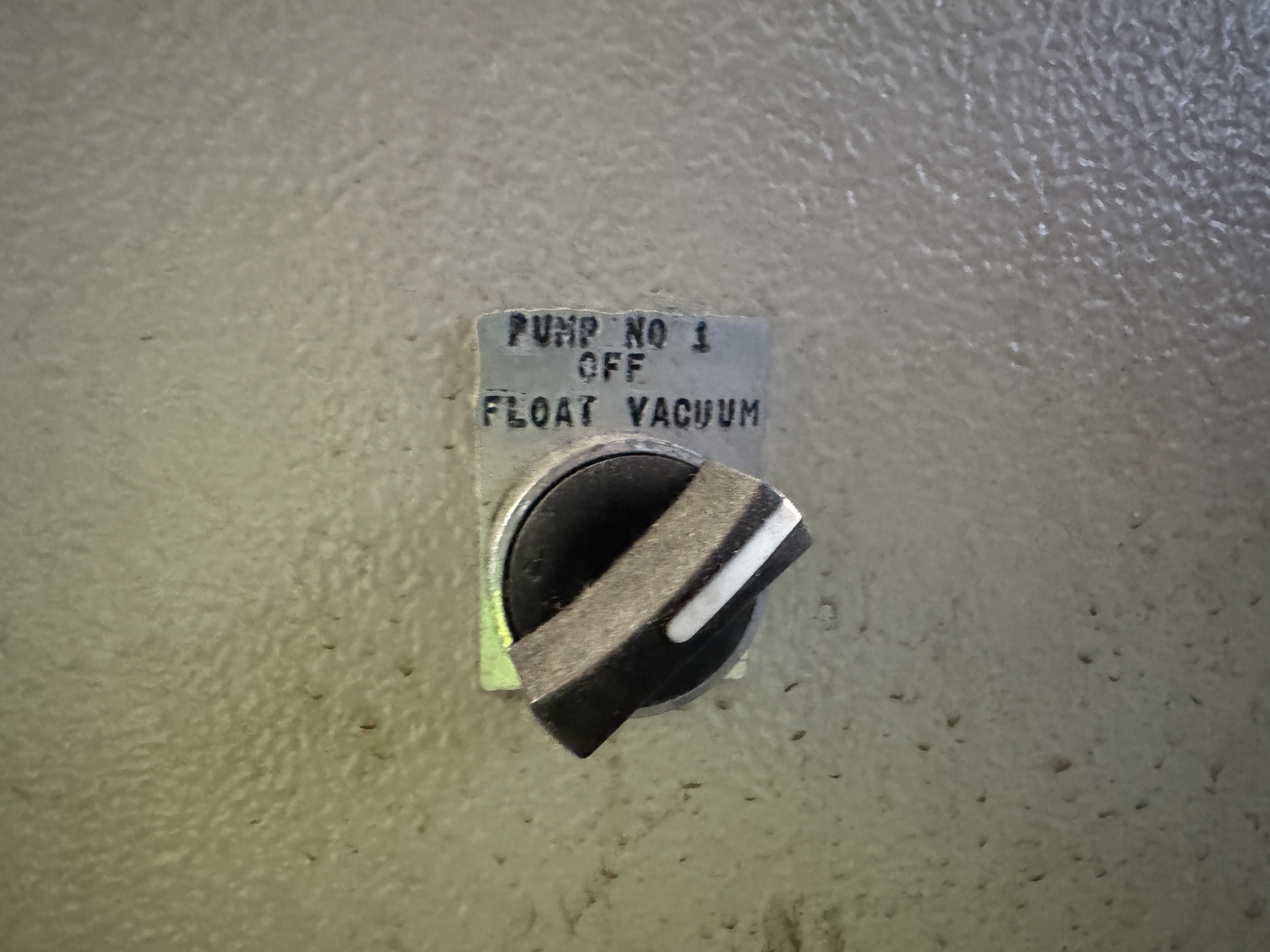
I took a look at the system during operation. The vacuum shutoff seems to be triggering, shutting down the vacuum pump at -2 PSIG cut-off, about 0 PSIG cut-in. Based on the material you sent, that seems suspect.
To add to the trouble, while running the system today, I found that one of the steam traps in this basement section is letting through > 212 degree steam/condensate into the returns. Still waiting to get someone in to replace the cartridges.
In other news, I confirmed that the pressuretrol on the boiler system is triggering for each heating cycle (it is not the LWCO or other controls). I am waiting for some parts to add an auxiliary low pressure gauge. Hopefully this will help me tune the boiler side a bit better.
I also looked more into the modulating control. Everything for modulation/low fire seems to be disabled. It looks like even a linkage connection to control the air damper for low fire was removed. Still searching for who did that.
Finally, I get to this point:
The recommended way to handle high condensate lifts is with a separate condensate tank and pump set to serve as a mechanical lift. The attached file has the details.
I'm looking at If I can reserve an additional mechanical space in the basement. I might be able to pipe all the basement radiators to a single collection point and then put in a condensate pump to put the condensate back into an existing return. This seems like it could be more reliable and conventional. Not sure I can make it fit into the budget, but it seems plausible.
0 -
If you have failed open steam traps the vacuum pump isn't going to be able to pull a vacuum
1 -
If I'm understanding everything correctly, Goulds is only the manufacturer of the centrifugal pump. Your unit was assembled from components bought from others and assembled by the nameplate manufacturer.
Your vacuum unit has a diverter valve, I believe its the solenoid valve, that selects where the Goulds pump discharges to; directly back to the boiler, or through the venturi nozzles to produce the vacuum, or some of each. Typically, units like yours do not have simultaneous air and water pumping capacity.
The performance curve displayed above only shows capacity when all the discharged condensate is going to the boiler or other final destination. When producing a vacuum, the volume capacity pumped to the boiler is less.
One well known brand of this type of vacuum pump that uses a 3/4 HP centrifugal pump is showing for a 20 PSI discharge pressure, 7.5 GPM, or 7 GPM and 3 CFM air simultaneous capacity. Another brand is showing 7.5 GPM, but for simultaneous air (vacuum) and water capacity, its 2.5 GPM and 2.5 CFM.
BTW, These are very small units; the smallest offered actually.
You'll need to consult the manufacturer of your unit to see what their actual air and water capacity ratings are.
As far as vacuum operation goes, the usual settings on the vacuum switch is OFF @ 8" Hg and ON again when the vacuum bleeds down to 3" Hg. to maintain an average 5.5" Hg. vacuum on your system. The vacuum switches are adjustable, but it's a rather tedious adjust and try process. There is no scale you can adjust a pointer to and get the results you want.
Dennis Pataki. Former Service Manager and Heating Pump Product Manager for Nash Engineering Company. Phone: 1-888 853 9963
Website: www.nashjenningspumps.com
The first step in solving any problem is TO IDENTIFY THE PROBLEM.0 -
Yes, you are understanding correctly. I am working on it. Thanks for your patience.
Thanks for the additional knowledge drop on typical vacuum pressures. After I get the steam traps fixed I will see if I can turn the vacuum higher (and turn down the pressure on the boiler).
For sure @mattmia2, I am trying to track down all the broken traps and get them fixed. I am getting closer. Thanks for all the tips.
0 -
For adjusting the usual Square D diaphragm type vacuum switches, I like to use a portable hand held vacuum pump like an auto mechanic would use to bleed brakes and check any vacuum operated accessories. This lets you have complete control over the vacuum supply and not have to rely on the sometimes dubious performance of the system's vacuum pump. See attached files.
On the other hand, if you can find an old Mercoid brand Bourdon tube and Mercury bottle vacuum switch, that's a better choice. They are dead simple to set, just adjust the 2 needles to the desired operating points. Also, they are bullet proof; they last forever. Only downside is they contain liquid Mercury, so be careful.
Just be sure the Mercoid switch is for vacuum only with the scale showing 0-30" Hg. and not the compound pressure and vacuum type. And also, be sure the switch is a NORMALLY CLOSED type, CONTACTS OPEN ON FALLING PRESSURE. Dwyer is the manufacturer and their product description is a bit confusing in this regard.
Dennis Pataki. Former Service Manager and Heating Pump Product Manager for Nash Engineering Company. Phone: 1-888 853 9963
Website: www.nashjenningspumps.com
The first step in solving any problem is TO IDENTIFY THE PROBLEM.1 -
+++ Mercoid vacuum switches. They are forever ! We look for them on eBay.
0 -
Heading out now to get a handheld pump to see if that Square D vacuum switch is salvageable. Thanks again. I'll also check that gauge is giving me reasonably accurate readings.
I found out this morning that the pressure gauge on the boiler is definitely just giving me garbage. There is a Hoffman #62 that is venting air into the boiler after shutdown. The gauge is telling me the boiler is still at 3 PSI when I hear air going back in. The replacement gauge is already on its way, just need to get the instrument drop header apart. That whole assembly is stuck together tightly. I need to figure out how to get them apart to replace the gauge and clean it out.
Hopefully next week will teach me a lot.
0 -
You can use a big syringe too although the mighty vac has a gauge built in which can be helpful.
0 -
A Hoffman #62 is a vacuum relief valve, AKA vacuum breaker. It is a spring loaded device that allows air from atmosphere to enter a closed area to bring the pressure up; closer to atmospheric. The compression on the spring adjusts the pressure differential needed to open the valve.
If this valve is naturally blowing air into the boiler room, it's leaking or stuck open.
These valves have an O ring seal that may need replacing.
See attached file.
Dennis Pataki. Former Service Manager and Heating Pump Product Manager for Nash Engineering Company. Phone: 1-888 853 9963
Website: www.nashjenningspumps.com
The first step in solving any problem is TO IDENTIFY THE PROBLEM.1 -
Yes, sorry. My wording was very imprecise.
The vacuum relief valve is working in the intended direction (allowing air into the boiler). I meant that clearly the boiler should be in vacuum if the relief valve is letting in air. I am not sure how much vacuum is being allowed by the valve, because the gauge is probably broken. My gauge is almost certainly broken if it is reading 3 PSI and the #62 is letting air into the boiler.
Is that clearer and mostly correct? Feel free to correct my wording as well, I really appreciate your generous help here.0 -
IMO, vacuum in the boiler is a good thing. Makes steam sooner and at a lower temperature.
The real question is, why is there a vacuum relief valve at the boiler? Is this vacuum causing any problem?
Under certain conditions vacuum at the boiler could cause boiler flooding problems, but that's actually a symptom, and there are solutions to resolve that.
Scrolling back through this thread, I don't see where we discussed equalizer lines. These are supposed to be there to equalize the pressure between the steam side and the return side so there is no unfavorable pressure differential that would prevent condensate from gravity draining back to the vacuum condensate pump's receiving tank. See attached file.
Dennis Pataki. Former Service Manager and Heating Pump Product Manager for Nash Engineering Company. Phone: 1-888 853 9963
Website: www.nashjenningspumps.com
The first step in solving any problem is TO IDENTIFY THE PROBLEM.0 -
Sorry for the delay, been trying to fix up the controls and steam traps. No dice yet on fixing the steam traps, but I am able to see accurate pressures now. Looks like I am typically going between 4 cut-out to 1.5 cut-in. Once I fix the steam traps, getting a new pressuretrol (or vaporstat) seems to be the order of the day.
After the system is off, the vacuum breaker starts letting in air at 1 “Hg, so not letting much of a vacuum happen.
Re: running in vacuum, I’d love to run this with a bit of vacuum in the boiler. I see one equalizer line that looks almost exactly like your example @Pumpguy. There is a gate valve on there with a broken handle. I don’t know if it is closed or open. Yet another bit of the system to take apart. Will try to confirm that everything is open and the check valve is working and then see if I can turn up the vacuum breaker tension to see what happens.
I also noticed that the vacuum assembly is connected to a vaporstat right where the mains split apart. This seems to be the main shutoff so it only runs when the boiler is on and hot.
thanks again. Fixing things bit by bit.0 -
Not sure I understand your "I also noticed that the vacuum assembly is connected to a vaporstat right where the mains split apart.".
Could you post some pictures so we get a clear understanding of this arrangement?
Dennis Pataki. Former Service Manager and Heating Pump Product Manager for Nash Engineering Company. Phone: 1-888 853 9963
Website: www.nashjenningspumps.com
The first step in solving any problem is TO IDENTIFY THE PROBLEM.0 -
Brain fart. Not vaporstat. Aquastat.
0


Categories
- All Categories
- 87.3K THE MAIN WALL
- 3.2K A-C, Heat Pumps & Refrigeration
- 61 Biomass
- 429 Carbon Monoxide Awareness
- 120 Chimneys & Flues
- 2.1K Domestic Hot Water
- 5.8K Gas Heating
- 114 Geothermal
- 166 Indoor-Air Quality
- 3.7K Oil Heating
- 77 Pipe Deterioration
- 1K Plumbing
- 6.5K Radiant Heating
- 395 Solar
- 15.7K Strictly Steam
- 3.4K Thermostats and Controls
- 56 Water Quality
- 51 Industry Classes
- 50 Job Opportunities
- 18 Recall Announcements