Wood Boiler W/Storage Control Logic and Plumbing Diagram... How'd I do?

I will be programing a PLC with thermocouple at the locations given in the diagram. I am an electrician, not a heating tech. Let me know if my diagram and controls seem they will work correctly.
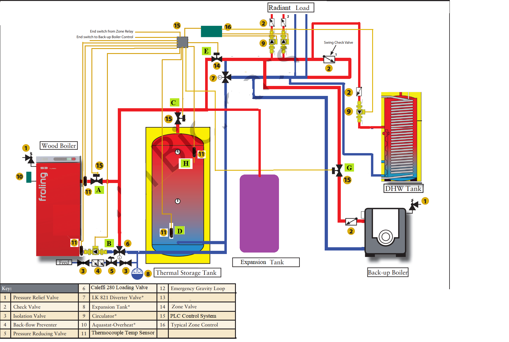
Theory of operation: If the wood boiler is at temp and house isn’t calling for heat, send the heat to the tank. If the wood boiler is at temp and the house calls for heat, send the heat to the load. If the house calls for heat the tank is at temp but wood boiler isn’t, send heat from the tank to the load (this will depend on whether it is a radiant (low temp) call or a DHW (high temp) call. If the wood boiler or the storage is not hot enough the oil boiler will fire.
1) -If the temperature at location “A” is above 100 degrees and there is at least a 10 degree difference between Location A and location B the circulator at location B turns on and the valve at location A opens
2) If the boiler return Location B is over 150 and the boiler output (location A) is hotter than Location D, and the house is NOT calling for heat the tank valve at location C opens.
3) If the boiler return Location B is over 160 and the boiler output (location A) is hotter than Location B and the house calls for heat, the valve at location C closes, the valve at location E opens, and circulator at location F energizes. (all valves/ circulators resume back to operation as in step #3)
4) If the boiler return Location B is NOT over 160 or the boiler output (location A) is NOT hotter than location B and the house calls for heat:
A) Valve at location A closes and Circulator at location B deenergizes. This holds trueuntil the temperature at location A exceeds 160.
B ) If zone calling for heat is radiant and the tank temperature at location H is above 100 the valves at location C & E opens, and the valve at location G closes. If the temp is not above 100 the valve at location G opens, Oil boiler is fired, and valve E is closed.
C) If zone calling for heat is DHW and the tank at location H is above 140 the valves at location C & E, and the valve at location G closes. If the temp is not above 100 the valve at location G opens, Oil boiler is fired, and valve E is closed.
5) If the tank rises above 200 it forces valves at locations A, C and E open and energizes circulators at location B. It also forces on the basement radiant zone which is 2600 of slab radiant. If the tank doesn’t drop below 200 for 5 minutes it triggers a trouble alarm output on my security system.
Here are more ways of saying the same theory of operation:
Anytime the oil boiler is operating the valve at location G is open. Valve at location E is closed.
Anytime the tank is feeding the heat load Valves at location G and A are closed and valve at location E is open.
Anytime the Wood Boiler is feeding the heat load the valves at location G and C are closed and valve A is open.
I will have a toggle switch on the control box that will either:
A) In normal position/operation Connect the zone controller end switch with the PLC input and the oil boiler control will be operated via a relay controlled by a PLC output.
B ) In Emergency Bypass position it will allow all function of the PLC to perform normally EXCEPT: It connects the zone controller end switch directly with the oil boiler control. This will allow the oil boiler to operate as a complete standalone system if there are any issues with controls/components.
I will have a digital readout of tank temp at location H and LED lights that will illuminate if each valve/ circulator is active.
I am relying on an automatic standby generator for power loss issues.
Comments
-
Mercy. Well, on the standby generator... how long a power interruption can the magic tolerate before it resets or reboots? You might want to power all that control circuity through a UPS.Br. Jamie, osb
Building superintendent/caretaker, 7200 sq. ft. historic house museum with dependencies in New England0 -
I had actually planned on a UPS for that exact reason.Jamie Hall said:Mercy. Well, on the standby generator... how long a power interruption can the magic tolerate before it resets or reboots? You might want to power all that control circuity through a UPS.0 -
you have a 3 pipe buffer tank, really no need to operate valve #15, or have a valve there
If the boiler circ is running moving say 10 gpm. All loads are running also flowing 10 gpm. All boiler output goes directly to load, the buffer is not in play
As load drops that portion of the gpm starts heating the buffer. When all loads satisfy full boiler output goes into the tank to setpoint
Next call for heat or DHW comes from the tank until it drops and calls the wood boil per first, If not ready then the backup boiler kicks on
If the back up boiler was piped at the buffer, it could also go direct to load
So a few piping changes could reduce the control complication
I had a system in my shop with solar thermal, wood gasification boiler and LP fired backup as the 3rd choice. 500 gallons of buffer piped for direct to load.
Bob "hot rod" Rohr
trainer for Caleffi NA
Living the hydronic dream 1
1 -
Why is it called a "3 pipe" design? I suppose not that it matters but I was shooting for a "2 pipe" design.hot_rod said:you have a 3 pipe buffer tank, really no need to operate valve #15, or have a valve there
If the boiler circ is running moving say 10 gpm. All loads are running also flowing 10 gpm. All boiler output goes directly to load, the buffer is not in play
As load drops that portion of the gpm starts heating the buffer. When all loads satisfy full boiler output goes into the tank to setpoint
Next call for heat or DHW comes from the tank until it drops and calls the wood boil per first, If not ready then the backup boiler kicks on
If the back up boiler was piped at the buffer, it could also go direct to load
So a few piping changes could reduce the control complication
I had a system in my shop with solar thermal, wood gasification boiler and LP fired backup as the 3rd choice. 500 gallons of buffer piped for direct to load.
Should I tee my WB return line in where my backup boiler return line is instead of having it on the same side of the diverter valve as the storage?
This is not 100% my diagram. I altered the diagram from Tarm to what I thought it should be. For an example, I don't see the need or the point of the loop with the check valve at the top left that connects the heating feed with the return. On my current system there is no loop there. My heating return line has a diverter valve to the return of the boiler and the feed to the load. I can update the drawing to show this.
Do you mean I shouldn't need any of the valve #15 at any location or just the #15 valve at location C?
I can visualize how the valve at location at C would not be needed. I was just concerned with if the heating load calls and the storage wasn't up to temp but the WB was might still try to pull from the storage.
I have a lot of reading time on this subject but still not 100% sure the physics behind making sure the heat feeds the right area or load pulls from the right area without the use of valves.
0 -
This is what I am talking about as far as return. I think this makes more sense would tie in better to what I have existing.

0 -
Do you want the back up boiler to heat the buffer also? If you have micro zones or if is a non modulating boiler you might run it through the buffer also
I don’t see a need for the “C” or 15? Valve? Isolation?
3 pipe as that is all the connections you need into the tank. Top and two bottom. I’m not sure why two blue lines go into the bottom right?Bob "hot rod" Rohr
trainer for Caleffi NA
Living the hydronic dream0 -
hot_rod said:
Do you want the back up boiler to heat the buffer also? If you have micro zones or if is a non modulating boiler you might run it through the buffer also
I don’t see a need for the “C” or 15? Valve? Isolation?
3 pipe as that is all the connections you need into the tank. Top and two bottom. I’m not sure why two blue lines go into the bottom right?
There actually is only 1 pipe in the top and one in the bottom of the tank. The one on the very bottom was just the return line for the WB. I made a new diagram to eliminate that confusion.
I had no plans to have the backup heat the buffer. It is a standard oil boiler with a tankless coil.
0 -
OK, I am going to stick my nose in here and say that you need and want simplicity to manage your heating system, you need to erase everything and start over.
The Froling will be piped to the backup boiler in series. The circulator will be piped above the oil boiler and the expansion tank will be close by to create the point of no pressure change.
The oil boiler will be piped to the heating load and the domestic hot water tank will be heated with the hot
water coming from the back up boiler which then goes to the heating load.
The cooler return water would go to the storage tank and be fed to the wood boiler to be reheated or pushed through to the backup boiler to be heated.
The expansion tank and air scoop or IAS, airtrol valve and steel compression tank and circulator need to be within 3 feet of each other to have the point of no pressure change and the.
You do not want or need the rats nest you have there just keep it simple with simple piping with hot a hot water header and cool water return to the storage tank and it is easier to manage.
Read Dans books CLASSIC HYDRONICS and PUMPING AWAY and you can keep it simple.
1 -
Are you abandoning the tankless coil in the boiler. If not, that boiler needs to maintain temperature.
How does the oil boiler output match the heat load. Often they are oversized to provide for the tankless coil. If so running that through the buffer would eliminate short cycling and keep the efficiency up.
I suspect that will not run much if you have wood and willingness?
Valve #7 is to mix a low temperature for the radiant?
But the oil boiler doesn't mix down when it runs?
This drawing for consideration has all inputs to the buffer and/ or direct to load. Both boilers get mixed down for radiant. Indirect gets heat from either source. Expansion tank on cooler return piping.
I spread out components to see piping better. The key with a buffer like this is it is also the hydraulic sep. So all connections from the boilers and to load need to be close to the tank on a large pipe, 1-1/4 or larger
I like differential controls for this sort of system as you use two sensors for better on off temperature control. The oil boiler for example only fires at a low tank condition, and needs to know when the wood boiler is back in the game.
Idronics 10 has some wiring schematics, this one is close to what you are proposing.Bob "hot rod" Rohr
trainer for Caleffi NA
Living the hydronic dream0 -
Are you saying the return from all the heat loads should only go to the tank?leonz said:OK, I am going to stick my nose in here and say that you need and want simplicity to manage your heating system, you need to erase everything and start over.
The Froling will be piped to the backup boiler in series. The circulator will be piped above the oil boiler and the expansion tank will be close by to create the point of no pressure change.
The oil boiler will be piped to the heating load and the domestic hot water tank will be heated with the hot
water coming from the back up boiler which then goes to the heating load.
The cooler return water would go to the storage tank and be fed to the wood boiler to be reheated or pushed through to the backup boiler to be heated.
The expansion tank and air scoop or IAS, airtrol valve and steel compression tank and circulator need to be within 3 feet of each other to have the point of no pressure change and the.
You do not want or need the rats nest you have there just keep it simple with simple piping with hot a hot water header and cool water return to the storage tank and it is easier to manage.
Read Dans books CLASSIC HYDRONICS and PUMPING AWAY and you can keep it simple.
Where should the boiler feeds come from then?
As far as the exact placement of the expansion tank, airtrol, ect dont go by the diagram. This diagram in only a plumbing schematic, not an actual layout. My friend that is master plumber/heater is helping me actually plumb it all up. He will know where the expansion tank, ect has to go. He is not at all fimilar with a wood boiler with storage and plumbing it all in with a backup. I told him I would figure those details out for him, which is why I am here.0 -
hot_rod said:
Are you abandoning the tankless coil in the boiler. If not, that boiler needs to maintain temperature.
How does the oil boiler output match the heat load. Often they are oversized to provide for the tankless coil. If so running that through the buffer would eliminate short cycling and keep the efficiency up.
I suspect that will not run much if you have wood and willingness?
Valve #7 is to mix a low temperature for the radiant?
But the oil boiler doesn't mix down when it runs?
This drawing for consideration has all inputs to the buffer and/ or direct to load. Both boilers get mixed down for radiant. Indirect gets heat from either source. Expansion tank on cooler return piping.
I spread out components to see piping better. The key with a buffer like this is it is also the hydraulic sep. So all connections from the boilers and to load need to be close to the tank on a large pipe, 1-1/4 or larger
I like differential controls for this sort of system as you use two sensors for better on off temperature control. The oil boiler for example only fires at a low tank condition, and needs to know when the wood boiler is back in the game.
Idronics 10 has some wiring schematics, this one is close to what you are proposing.
Okay, maybe I have my terms incorrect. I thought it was called a tankless coil. I do know it is a coldstart boiler. My friend is my plumber/heater. He is the one who is doing the work. I am trying to learn the system.
I do know the boiler does not have to stay hot, only runs when heat is being called for. (House is still being built and there is no DHW yet and it hasn't run since spring.
Good point on the Valve #7. Now that you say that technically it ties into the feed coming from the oil boiler, not exactly how I have it.
I wanted to use 2" on everything but can only find valves and circulators up to 1 1/4. Do you think that will be an issue?
I have read a decent amount on Idronics 10. As far as the wiring/programming that would be an issue for me, that is the field I excel in. It is more making sure the way I am actually controling it will work properly. Like the temperature setpoints, ect.
My thoughts with the PLC with thermocouple sensors vs ordinary relays and equastats is that it'll alow more control and adjustments. Instead of an "on/off" aquastat it can actually monitor the temp and I can have different actions/stages with one sensor per location.
Thank you for taking the time to guide me. I really appreciate your input.
Does this make a little more sense? Tried cleaning it up a little.
0 -
not really
") . When the back up boiler runs that temperature 160F or more can go directly to the radiant? It will not flow across that high pressure drop 17 valve? I don' like the way valve 7 is piped. I think you want both boilers able to flow across it?
. When the back up boiler runs that temperature 160F or more can go directly to the radiant? It will not flow across that high pressure drop 17 valve? I don' like the way valve 7 is piped. I think you want both boilers able to flow across it?
I don't see what valve 14 does. #15 maybe for isolation?
The key to 2 or 3 pipe buffer is a large pipe at the tank, maybe 2", keep all connections close to the tank, as shown in my drawings. Both boilers and the indirect need to be piped at the tank, into a large header pipe.
I don't see any need for motorized valves, assuming #17 is a thermostatic mix valve?
In my version both boilers, indirect and loads take off from right at the buffer, on a 2" header pipe. Other than some service isolation valves, all you need is the main radiant mix valve. Control-wise all my system requires is a way to pull on the backup boiler, no other valves to control. A simple delta∆ control really.
The mix valves I use are hot and cold across from one another, the mix straight down, like a tee. Some brands have the port H,C and M in different locations.
Bob "hot rod" Rohr
trainer for Caleffi NA
Living the hydronic dream1 -
==================================================================================================================================TuckerTerra said:
Are you saying the return from all the heat loads should only go to the tank?leonz said:OK, I am going to stick my nose in here and say that you need and want simplicity to manage your heating system, you need to erase everything and start over.
The Froling will be piped to the backup boiler in series. The circulator will be piped above the oil boiler and the expansion tank will be close by to create the point of no pressure change.
The oil boiler will be piped to the heating load and the domestic hot water tank will be heated with the hot
water coming from the back up boiler which then goes to the heating load.
The cooler return water would go to the storage tank and be fed to the wood boiler to be reheated or pushed through to the backup boiler to be heated.
The expansion tank and air scoop or IAS, airtrol valve and steel compression tank and circulator need to be within 3 feet of each other to have the point of no pressure change and the.
You do not want or need the rats nest you have there just keep it simple with simple piping with hot a hot water header and cool water return to the storage tank and it is easier to manage.
Read Dans books CLASSIC HYDRONICS and PUMPING AWAY and you can keep it simple.
Where should the boiler feeds come from then?
As far as the exact placement of the expansion tank, airtrol, ect dont go by the diagram. This diagram in only a plumbing schematic, not an actual layout. My friend that is master plumber/heater is helping me actually plumb it all up. He will know where the expansion tank, ect has to go. He is not at all fimilar with a wood boiler with storage and plumbing it all in with a backup. I told him I would figure those details out for him, which is why I am here.
You need to make sure you use black iron pipe for near boiler piping at least on the Froling boiler as it will withstand the heat of expansion better.
Pipe in series from the Froling out tapping to the inlet of the oil boiler and then the heat exchanger and then the heating loads and back to the storage tank and then to the inlet of the Froling.
If you use Dans Drawing from page 53 of "PUMPING AWAY" creating a pump module to plumb in the top tapping of the oil boiler you won't go wrong.
Just be sure to run a single pipe from the Frolings hot side tapping to the oil boiler sump tapping with unions and then come off the top of the pump module with the line that goes to the domestic coil and then the zones.
You can always install a vertical pipe on the Froling as shown in Dans Drawing and just end it with a TEE, a pipe plug and the boiler drain and a reducing bushing as shown in his drawing and bleed all the air out of the steam chest and you can connect a can of FERNOX to the boiler drain and feed it into either boiler to treat the boiler water.
If you use a single B+G 30 gallon Steel compression tank for both boilers with the B+G water level guage for that steel compression tank and you can build the single pump module for the oil boiler to take care of both boilers and use the B+G Internal Air Separator and B+G Airtrol Valve and you can plumb in the rest of the pipe to the zone valves and the domestic coil tank.
I like not having to crawl around on my replacement knees as the air blanket over the water in the steel compression tank quickly helps to remove any air bubbles coming from the Internal Air Separator that rise into the airtrol valve. If I had cast iron radiators my heating system would be even better.
0 -
No, you are correct. There is a mixing valve or something someplace that I am missing. I will have to go down to my house tomorrow and look and see how it is done, I am drawing a blank. It is not feeding 160+ water to the radiant. I am sure I have valve 7 drawn incorrect. Look at my new diagram below, see if that makes more sense now. I dont have 3 lines coming out of my tank so I am trying to understand. The valves near locations A G and C I put there for isolation.hot_rod said:not really
. When the back up boiler runs that temperature 160F or more can go directly to the radiant? It will not flow across that high pressure drop 17 valve? I don' like the way valve 7 is piped. I think you want both boilers able to flow across it?
I don't see what valve 14 does. #15 maybe for isolation?
The key to 2 or 3 pipe buffer is a large pipe at the tank, maybe 2", keep all connections close to the tank, as shown in my drawings. Both boilers and the indirect need to be piped at the tank, into a large header pipe.
I don't see any need for motorized valves, assuming #17 is a thermostatic mix valve?
In my version both boilers, indirect and loads take off from right at the buffer, on a 2" header pipe. Other than some service isolation valves, all you need is the main radiant mix valve. Control-wise all my system requires is a way to pull on the backup boiler, no other valves to control. A simple delta∆ control really.
The mix valves I use are hot and cold across from one another, the mix straight down, like a tee. Some brands have the port H,C and M in different locations.
Are you saying I should allow my hot wood boiler water to flow through the oil boiler? So if the wood boiler water isnt hot enough the oil would heat it up more?leonz said:
You need to make sure you use black iron pipe for near boiler piping at least on the Froling boiler as it will withstand the heat of expansion better.
Pipe in series from the Froling out tapping to the inlet of the oil boiler and then the heat exchanger and then the heating loads and back to the storage tank and then to the inlet of the Froling.
If you use Dans Drawing from page 53 of "PUMPING AWAY" creating a pump module to plumb in the top tapping of the oil boiler you won't go wrong.
Just be sure to run a single pipe from the Frolings hot side tapping to the oil boiler sump tapping with unions and then come off the top of the pump module with the line that goes to the domestic coil and then the zones.
You can always install a vertical pipe on the Froling as shown in Dans Drawing and just end it with a TEE, a pipe plug and the boiler drain and a reducing bushing as shown in his drawing and bleed all the air out of the steam chest and you can connect a can of FERNOX to the boiler drain and feed it into either boiler to treat the boiler water.
If you use a single B+G 30 gallon Steel compression tank for both boilers with the B+G water level guage for that steel compression tank and you can build the single pump module for the oil boiler to take care of both boilers and use the B+G Internal Air Separator and B+G Airtrol Valve and you can plumb in the rest of the pipe to the zone valves and the domestic coil tank.
I like not having to crawl around on my replacement knees as the air blanket over the water in the steel compression tank quickly helps to remove any air bubbles coming from the Internal Air Separator that rise into the airtrol valve. If I had cast iron radiators my heating system would be even better.
0 -
You are correct, I was wrong how I had that drawn. I am trying to follow, however since I only have 2 pipes in my storage tank it will be different. The purpose of those valves above the boilers and tank is just for isolation. Check out the new diagram below and see if that fixes those issues and makes more sense.hot_rod said:not really
. When the back up boiler runs that temperature 160F or more can go directly to the radiant? It will not flow across that high pressure drop 17 valve? I don' like the way valve 7 is piped. I think you want both boilers able to flow across it?
I don't see what valve 14 does. #15 maybe for isolation?
The key to 2 or 3 pipe buffer is a large pipe at the tank, maybe 2", keep all connections close to the tank, as shown in my drawings. Both boilers and the indirect need to be piped at the tank, into a large header pipe.
I don't see any need for motorized valves, assuming #17 is a thermostatic mix valve?
In my version both boilers, indirect and loads take off from right at the buffer, on a 2" header pipe. Other than some service isolation valves, all you need is the main radiant mix valve. Control-wise all my system requires is a way to pull on the backup boiler, no other valves to control. A simple delta∆ control really.
The mix valves I use are hot and cold across from one another, the mix straight down, like a tee. Some brands have the port H,C and M in different locations.
0 -
Are you saying I should have is so the output of my wood boiler feeds the cold water side of my oil boiler? instead of bypassing it?leonz said:
==================================================================================================================================TuckerTerra said:
Are you saying the return from all the heat loads should only go to the tank?leonz said:OK, I am going to stick my nose in here and say that you need and want simplicity to manage your heating system, you need to erase everything and start over.
The Froling will be piped to the backup boiler in series. The circulator will be piped above the oil boiler and the expansion tank will be close by to create the point of no pressure change.
The oil boiler will be piped to the heating load and the domestic hot water tank will be heated with the hot
water coming from the back up boiler which then goes to the heating load.
The cooler return water would go to the storage tank and be fed to the wood boiler to be reheated or pushed through to the backup boiler to be heated.
The expansion tank and air scoop or IAS, airtrol valve and steel compression tank and circulator need to be within 3 feet of each other to have the point of no pressure change and the.
You do not want or need the rats nest you have there just keep it simple with simple piping with hot a hot water header and cool water return to the storage tank and it is easier to manage.
Read Dans books CLASSIC HYDRONICS and PUMPING AWAY and you can keep it simple.
Where should the boiler feeds come from then?
As far as the exact placement of the expansion tank, airtrol, ect dont go by the diagram. This diagram in only a plumbing schematic, not an actual layout. My friend that is master plumber/heater is helping me actually plumb it all up. He will know where the expansion tank, ect has to go. He is not at all fimilar with a wood boiler with storage and plumbing it all in with a backup. I told him I would figure those details out for him, which is why I am here.
You need to make sure you use black iron pipe for near boiler piping at least on the Froling boiler as it will withstand the heat of expansion better.
Pipe in series from the Froling out tapping to the inlet of the oil boiler and then the heat exchanger and then the heating loads and back to the storage tank and then to the inlet of the Froling.
If you use Dans Drawing from page 53 of "PUMPING AWAY" creating a pump module to plumb in the top tapping of the oil boiler you won't go wrong.
Just be sure to run a single pipe from the Frolings hot side tapping to the oil boiler sump tapping with unions and then come off the top of the pump module with the line that goes to the domestic coil and then the zones.
You can always install a vertical pipe on the Froling as shown in Dans Drawing and just end it with a TEE, a pipe plug and the boiler drain and a reducing bushing as shown in his drawing and bleed all the air out of the steam chest and you can connect a can of FERNOX to the boiler drain and feed it into either boiler to treat the boiler water.
If you use a single B+G 30 gallon Steel compression tank for both boilers with the B+G water level guage for that steel compression tank and you can build the single pump module for the oil boiler to take care of both boilers and use the B+G Internal Air Separator and B+G Airtrol Valve and you can plumb in the rest of the pipe to the zone valves and the domestic coil tank.
I like not having to crawl around on my replacement knees as the air blanket over the water in the steel compression tank quickly helps to remove any air bubbles coming from the Internal Air Separator that rise into the airtrol valve. If I had cast iron radiators my heating system would be even better.0 -
Yes, now you have a true primary/ secondary with the buffer as the separatorTuckerTerra said:not really
You are correct, I was wrong how I had that drawn. I am trying to follow, however since I only have 2 pipes in my storage tank it will be different. The purpose of those valves above the boilers and tank is just for isolation. Check out the new diagram below and see if that fixes those issues and makes more sense.. When the back up boiler runs that temperature 160F or more can go directly to the radiant? It will not flow across that high pressure drop 17 valve? I don' like the way valve 7 is piped. I think you want both boilers able to flow across it?
I don't see what valve 14 does. #15 maybe for isolation?
The key to 2 or 3 pipe buffer is a large pipe at the tank, maybe 2", keep all connections close to the tank, as shown in my drawings. Both boilers and the indirect need to be piped at the tank, into a large header pipe.
I don't see any need for motorized valves, assuming #17 is a thermostatic mix valve?
In my version both boilers, indirect and loads take off from right at the buffer, on a 2" header pipe. Other than some service isolation valves, all you need is the main radiant mix valve. Control-wise all my system requires is a way to pull on the backup boiler, no other valves to control. A simple delta∆ control really.
The mix valves I use are hot and cold across from one another, the mix straight down, like a tee. Some brands have the port H,C and M in different locations.
All the connections need to be right at the tank, within 12” or less
Does the tank only have one top and one side connection? Or 4 connection as the drawing shows?
You really do not want the boilers in series. The oil boiler turns into a cooling tower! Never flow through an unfired boiler as a % of the heat goes up the flue of that unfired device
From boiler directly to load. When loads are satisfied the buffer becomes the load until it reaches temperature
You don’t show a heat dump, so you will want to watch how you load the wood boiler to prevent overheating when all loads satisfy
Bob "hot rod" Rohr
trainer for Caleffi NA
Living the hydronic dream0 -
My tank is 500 gallons, so it is quite large. It is located about 5' from the wood boiler and about 10 from the oil boiler. I can't get it much closer due to the size and layout of everything.hot_rod said:
Yes, now you have a true primary/ secondary with the buffer as the separatorTuckerTerra said:not really
You are correct, I was wrong how I had that drawn. I am trying to follow, however since I only have 2 pipes in my storage tank it will be different. The purpose of those valves above the boilers and tank is just for isolation. Check out the new diagram below and see if that fixes those issues and makes more sense.. When the back up boiler runs that temperature 160F or more can go directly to the radiant? It will not flow across that high pressure drop 17 valve? I don' like the way valve 7 is piped. I think you want both boilers able to flow across it?
I don't see what valve 14 does. #15 maybe for isolation?
The key to 2 or 3 pipe buffer is a large pipe at the tank, maybe 2", keep all connections close to the tank, as shown in my drawings. Both boilers and the indirect need to be piped at the tank, into a large header pipe.
I don't see any need for motorized valves, assuming #17 is a thermostatic mix valve?
In my version both boilers, indirect and loads take off from right at the buffer, on a 2" header pipe. Other than some service isolation valves, all you need is the main radiant mix valve. Control-wise all my system requires is a way to pull on the backup boiler, no other valves to control. A simple delta∆ control really.
The mix valves I use are hot and cold across from one another, the mix straight down, like a tee. Some brands have the port H,C and M in different locations.
All the connections need to be right at the tank, within 12” or less
Does the tank only have one top and one side connection? Or 4 connection as the drawing shows?
You really do not want the boilers in series. The oil boiler turns into a cooling tower! Never flow through an unfired boiler as a % of the heat goes up the flue of that unfired device
From boiler directly to load. When loads are satisfied the buffer becomes the load until it reaches temperature
You don’t show a heat dump, so you will want to watch how you load the wood boiler to prevent overheating when all loads satisfy
The tank is like my diagram, one 2" inlet on the top and one 2" outlet out the bottom.
I have the Caleffi 280 wood boiler loading valve but it is only 1 1/4". That's the largest have found. My woodboiler and tank is 2". Am I going to be okay reducing it all down to 1 1/4 and still get the GPH and BTU output?
I didn't think having the boilers in series would be best, unless the water from the wood boiler is not quite warm enough for the loads.
I dont have plans for a heat dump yet, but that may still happen. I am hoping to not need one...
Do I need any other circulators other than the ones I show?0 -
Tarm ALWAYS includes a heat dump in their designs (you found it expedient to eliminate it). All solid fuel boilers need them. You say you "hope not to need one"...well, we ALL hope NOT to need one. Good luck without one.0
-
Isn't the 500 gallon tank technically a heat dump?psb75 said:Tarm ALWAYS includes a heat dump in their designs (you found it expedient to eliminate it). All solid fuel boilers need them. You say you "hope not to need one"...well, we ALL hope NOT to need one. Good luck without one.
Also, not that it matters but my wood boiler is actually a Buderus Non-Gasser, not a Tarm. I know the diagram shows a Tarm but that is just cause that is the original diagram I started off with.0 -
YES!!!!!!!!!!!!!!!!!!!!!!!!!!!!!!!!!!!!!!!!!!!!!!!!!!!!!!!!!!!!!!!!!!!!!!!!!!!!!!!!!!!!!!!!!!!!!!!!!!!!!!!!!!!!!!!!!!!!!!!!!!!!!!!!!!!!!!!TuckerTerra said:
Are you saying I should have is so the output of my wood boiler feeds the cold water side of my oil boiler? instead of bypassing it?leonz said:
==================================================================================================================================TuckerTerra said:
Are you saying the return from all the heat loads should only go to the tank?leonz said:OK, I am going to stick my nose in here and say that you need and want simplicity to manage your heating system, you need to erase everything and start over.
The Froling will be piped to the backup boiler in series. The circulator will be piped above the oil boiler and the expansion tank will be close by to create the point of no pressure change.
The oil boiler will be piped to the heating load and the domestic hot water tank will be heated with the hot
water coming from the back up boiler which then goes to the heating load.
The cooler return water would go to the storage tank and be fed to the wood boiler to be reheated or pushed through to the backup boiler to be heated.
The expansion tank and air scoop or IAS, airtrol valve and steel compression tank and circulator need to be within 3 feet of each other to have the point of no pressure change and the.
You do not want or need the rats nest you have there just keep it simple with simple piping with hot a hot water header and cool water return to the storage tank and it is easier to manage.
Read Dans books CLASSIC HYDRONICS and PUMPING AWAY and you can keep it simple.
Where should the boiler feeds come from then?
As far as the exact placement of the expansion tank, airtrol, ect dont go by the diagram. This diagram in only a plumbing schematic, not an actual layout. My friend that is master plumber/heater is helping me actually plumb it all up. He will know where the expansion tank, ect has to go. He is not at all fimilar with a wood boiler with storage and plumbing it all in with a backup. I told him I would figure those details out for him, which is why I am here.
You need to make sure you use black iron pipe for near boiler piping at least on the Froling boiler as it will withstand the heat of expansion better.
Pipe in series from the Froling out tapping to the inlet of the oil boiler and then the heat exchanger and then the heating loads and back to the storage tank and then to the inlet of the Froling.
If you use Dans Drawing from page 53 of "PUMPING AWAY" creating a pump module to plumb in the top tapping of the oil boiler you won't go wrong.
Just be sure to run a single pipe from the Frolings hot side tapping to the oil boiler sump tapping with unions and then come off the top of the pump module with the line that goes to the domestic coil and then the zones.
You can always install a vertical pipe on the Froling as shown in Dans Drawing and just end it with a TEE, a pipe plug and the boiler drain and a reducing bushing as shown in his drawing and bleed all the air out of the steam chest and you can connect a can of FERNOX to the boiler drain and feed it into either boiler to treat the boiler water.
If you use a single B+G 30 gallon Steel compression tank for both boilers with the B+G water level guage for that steel compression tank and you can build the single pump module for the oil boiler to take care of both boilers and use the B+G Internal Air Separator and B+G Airtrol Valve and you can plumb in the rest of the pipe to the zone valves and the domestic coil tank.
I like not having to crawl around on my replacement knees as the air blanket over the water in the steel compression tank quickly helps to remove any air bubbles coming from the Internal Air Separator that rise into the airtrol valve. If I had cast iron radiators my heating system would be even better.
It will not be so cold that the water coming from the buffer tank and going to the sump of the Froling boiler will cause any harm to the Froling boiler.0 -
what size If that boiler is 60 Kw or less my, -1/4 is okay for pipe size from the boilers
The various components do not need to be close together physically, just the way they pipe, here is an example of how the tank needs to pipe to work correctly. My wood boiler was 30’ from the tank.
Get a bunch is 2” x 4” long nipples to build the headers. Then four 2x 1-1/4 tees, four 2x1 tees
2” cap, 2 x 1/2 reducing coupling for the air vent
i would build that with threaded pipe to adjust the tee positions. Those headers will be about 24” long. It could be horizontal off the top of the tank if needed
Euro gasification boilers have small fire boxes. With 500 gallons of buffer you could get away without overheating. Run the wood boiler at 170-180, you could coast the tank to 190- 200 as overheat capacity. Those boilers just pulse the fan to keep the fire from going out when the hit setpoint, so a very slow temperature overshoot to accommodate. You will learn how to load the wood based on weather conditions
Or build a control that runs a zone or indirect pump for overheat. If the wood boiler reaches 200F call on any load
Four pumps plus the 280 is all you need with this piping. I left out service/ iso valves and exp tank for a cleaner drawing
connect the expansion tank into the bottom header anywhereBob "hot rod" Rohr
trainer for Caleffi NA
Living the hydronic dream0 -
hot_rod said:
what size If that boiler is 60 Kw or less my, -1/4 is okay for pipe size from the boilers
The various components do not need to be close together physically, just the way they pipe, here is an example of how the tank needs to pipe to work correctly. My wood boiler was 30’ from the tank.
Get a bunch is 2” x 4” long nipples to build the headers. Then four 2x 1-1/4 tees, four 2x1 tees
2” cap, 2 x 1/2 reducing coupling for the air vent
i would build that with threaded pipe to adjust the tee positions. Those headers will be about 24” long. It could be horizontal off the top of the tank if needed
Euro gasification boilers have small fire boxes. With 500 gallons of buffer you could get away without overheating. Run the wood boiler at 170-180, you could coast the tank to 190- 200 as overheat capacity. Those boilers just pulse the fan to keep the fire from going out when the hit setpoint, so a very slow temperature overshoot to accommodate. You will learn how to load the wood based on weather conditions
Or build a control that runs a zone or indirect pump for overheat. If the wood boiler reaches 200F call on any load
Four pumps plus the 280 is all you need with this piping. I left out service/ iso valves and exp tank for a cleaner drawing
connect the expansion tank into the bottom header anywhere
The boiler is rated at 140,000 BTU
that was my plan with the overheat, to watch and plan ahead with stoking and also I had planned to have the control system force on the basement (2600 sqft slab) radiant if the tank or boiler hits 200 degrees. I know radiant should be used as a high temp heat dump but that is a huge heat sink to dump heat in if need be.
Okay, that drawing you attached helps me visualize the header. Thanks for that!
So your saying I should also have a pump on the return of the oil boiler, as well as the wood boiler...?
0 -
Pumps could be in either supply or return with this piping method
i like them on return so they run in cooler fluid. Especially on wood fired systems where overheat in inevitable 🤓At least a few times until you and the boiler learn to get alongBob "hot rod" Rohr
trainer for Caleffi NA
Living the hydronic dream0 -
I built my buffer from a 500 gallon LP tank. Welded two 3" headers into the side of the tank. 3 inputs, 3 different loads
Solar input, wood boiler input, LP back up input
Radiant load, DHW load, high temperature panel rad zoneBob "hot rod" Rohr
trainer for Caleffi NA
Living the hydronic dream0 -
Another nice option is to use a motorized mix valve instead of a thermostatic, for the radiant. that extends the draw down or usefulness of the buffer. Makes for a more comfortable radiant also.
A differential control would also add some more tank use-ability.Bob "hot rod" Rohr
trainer for Caleffi NA
Living the hydronic dream0 -
I also have a Buderus "non-gasser" wood boiler in the cellar. I have 800 gals. of heat storage. AND I also have a "powered closed" zone valve that opens if the house loses power. My boiler will then thermo-siphon all heat to cast iron radiators on the 1st floor above.1
-
You heat your buffer with your LP as well?hot_rod said:I built my buffer from a 500 gallon LP tank. Welded two 3" headers into the side of the tank. 3 inputs, 3 different loads Solar input, wood boiler input, LP back up input Radiant load, DHW load, high temperature panel rad zone0 -
Yeah I am going to try to use the tank down to 80 degrees for the radiant zones.hot_rod said:Another nice option is to use a motorized mix valve instead of a thermostatic, for the radiant. that extends the draw down or usefulness of the buffer. Makes for a more comfortable radiant also. A differential control would also add some more tank use-ability.
So I have a circulator on the return of the wood boiler, a circulator on the return of the backup oil boiler, I don't need one on the tank though?
0 -
I have no high temperature heat zones, except for maybe my garage, which would require power cause it would be a Modine. I can add a radiator someplace. I just dont know that the .1% chance that the wood boiler is cranking, I lose power AND my automatic standby generator doesn't start makes it worth it.psb75 said:I also have a Buderus "non-gasser" wood boiler in the cellar. I have 800 gals. of heat storage. AND I also have a "powered closed" zone valve that opens if the house loses power. My boiler will then thermo-siphon all heat to cast iron radiators on the 1st floor above.0 -
I calculated I needed roughly a 70 gallon expansion tank, does that make sense?hot_rod said:Another nice option is to use a motorized mix valve instead of a thermostatic, for the radiant. that extends the draw down or usefulness of the buffer. Makes for a more comfortable radiant also. A differential control would also add some more tank use-ability.
Are there specific circulators you recommend?0 -
Yeah I am going to try to use the tank down to 80 degrees for the radiant zones.TuckerTerra said:hot_rod said:Another nice option is to use a motorized mix valve instead of a thermostatic, for the radiant. that extends the draw down or usefulness of the buffer. Makes for a more comfortable radiant also.
A differential control would also add some more tank use-ability.
So I have a circulator on the return of the wood boiler, a circulator on the return of the backup oil boiler, I don't need one on the tank though?
No circ on the tank. Either the boilers or the loads will move flow through it. Possibly multiple circs will run together.Bob "hot rod" Rohr
trainer for Caleffi NA
Living the hydronic dream1 -
I calculated I needed roughly a 70 gallon expansion tank, does that make sense?TuckerTerra said:hot_rod said:Another nice option is to use a motorized mix valve instead of a thermostatic, for the radiant. that extends the draw down or usefulness of the buffer. Makes for a more comfortable radiant also.
A differential control would also add some more tank use-ability.
Are there specific circulators you recommend?
Using the Amtrol sizer, free at their website, here are the results. I assumed 600 gallons total. Maybe more?
It is often less $$ to use multiple small tanks, price a few option. Adjust their pre-charge pressure and tee them together.
All of the pump brands are making a wide selection these days. I've used Grundfos Alphas mainly.Bob "hot rod" Rohr
trainer for Caleffi NA
Living the hydronic dream1 -
You heat your buffer with your LP as well?TuckerTerra said:hot_rod said:I built my buffer from a 500 gallon LP tank. Welded two 3" headers into the side of the tank. 3 inputs, 3 different loads
Solar input, wood boiler input, LP back up input
Radiant load, DHW load, high temperature panel rad zone
I welded a side tap about 24" from the top of my tank. So the LP boiler only heated about 30 gallons of the tank. I did that because the DHW came off a plate heat exchanger. On my second version I used a combi boiler so DHW was directly from the boiler, no need to keep the buffer hot.
Since I had side taps I was able to leave a large air bubble up top. That was my expansion tank, and the air bubble for the solar drainback to drain into.
The air purger on the system was piped up to that air space.Bob "hot rod" Rohr
trainer for Caleffi NA
Living the hydronic dream1


Categories
- All Categories
- 87.7K THE MAIN WALL
- 3.3K A-C, Heat Pumps & Refrigeration
- 59 Biomass
- 430 Carbon Monoxide Awareness
- 127 Chimneys & Flues
- 2.2K Domestic Hot Water
- 5.9K Gas Heating
- 121 Geothermal
- 170 Indoor-Air Quality
- 3.8K Oil Heating
- 79 Pipe Deterioration
- 1.1K Plumbing
- 6.6K Radiant Heating
- 396 Solar
- 16K Strictly Steam
- 3.5K Thermostats and Controls
- 56 Water Quality
- 51 Industry Classes
- 51 Job Opportunities
- 17 Recall Announcements