Welcome! Here are the website rules, as well as some tips for using this forum.
Need to contact us? Visit https://heatinghelp.com/contact-us/.
Click here to Find a Contractor in your area.
If our community has helped you, please consider making a contribution to support this website. Thanks!
Boiler Plumbing Advice
Options

patrickoneal
Member Posts: 7
I'm replacing an oversized cast iron hot water boiler with a Navien 80k btu modcon. I have a 40 gallon indirect tank that I will be keeping and using with the new boiler. I've got space in my garage to do so, so I want to pre-fab as much of the plumbing as I can before I switch out the boiler.
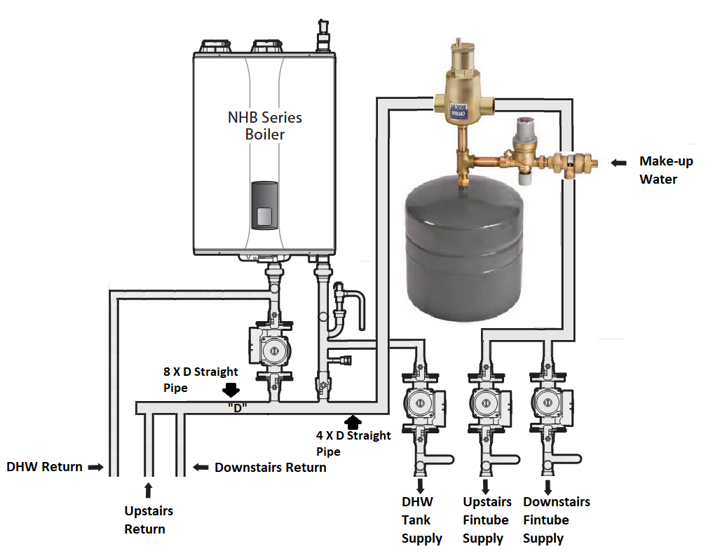
I've studied the manual and I have acquired the prefabricated manifold to go with the boiler. The boiler will be mounted on the wall in my attached garage, and the supply and return piping all emerges from the wall near the floor. I've attached a quick and dirty sketch of the proposed layout of my components, and I have a few questions if anyone would be kind enough to provide some advice.
1. In an effort to conserve wall space I have a lot of elbows to get up to the expansion tank and air separator before turning back down and around to the zone pumps. I'm aware that I have to have 4 diameters of straight pipe after the closely spaced tees before the first elbow. Other than that rule, is there any problem with taking such a circuitous route to the zone pumps?
2. The main pipe with the primary tees is 1 1/2" copper(I've labeled it "D"). Both sets of my supply and return pipes are 3/4" copper. Should I maintain 1 1/2" pipe through the air separator all the way to each of the two zone pumps? Or is a smaller size acceptable?
3. Should I maintain 1 1/2" copper pipe up to the point that my zone return pipes connect?
4. I'm aware of the importance of the spacing of the primary loop tees, and the requirement for minimum amounts of straight pipe on each side of the tees. I haven't read anything about spacing out other components. Is there any required spacing between the zone pumps or should I just put them far enough apart to comfortably access each pump for maintenance and replacement?
5. As in question #4, should I space out my zone return pipe connections?
Thank you for any advice you may have for me.
0
Comments
-
Nothing wrong with that layout at all. A single 1" main will feed more than two 3/4" branches can use, so no need to keep the 1-1/2" so long as the 3/4" is adequate for the zones. The air eliminator doesn't need to be at a high point, it'll do its job anywhere on the supply side if that helps save any space. Spacing of the zone tees can be as tight as you like with no ill effects- just make sure those new pumps have an IFC to keep one from backfeeding the other.1
-
Unless you have high flow requirements on the system side, you should be able the pipe it all in 1".
You will want to make sure you have check valves on the circs.
Give yourself plenty of ways to purge the system.
Air separators also tend to act as dirt separators. Your expansion tank will live longer if you pipe a blowdown valve under the separator and pipe the expansion tank off to the side."If you can't explain it simply, you don't understand it well enough"
Albert Einstein1 -
GroundUp and Zman, thank you so much for your replies.
Navien mentions the IFCs on the zone pumps and seems to recommend one on the boiler pump as well. I was planning to make sure all four pumps have check valves.
As far as stepping the piping down to 1", can I do that at the ends of the 1 1/2" pipe on the manifold? I've attached a photograph of it. Or should I extend the pipes prior to reducing it? I know I need some straight pipe after each tee, and I can't see how reducing it there would hurt anything.
0 -
It's probably a good idea to keep the recommended diameters before reducing. I think it will work either way."If you can't explain it simply, you don't understand it well enough"
Albert Einstein1 -
Thanks again Zman. The 4x and 8x measurements of straight pipe were something I found on google. Looking closer, it looks like a lot of manufacturers recommend 6x diameters on both sides. I think they're talking nominal rather than actual diameter. Navien is silent on the matter in their manual, but if it's needed I don't want to have to go back and redo a bunch of plumbing.0
-
If you get it close to those numbers, you will be good. In many installations, there just isn't room. Just do the best you can."If you can't explain it simply, you don't understand it well enough"
Albert Einstein0 -
You will want to put a ball valve somewhere between the boiler and the fill valve and a drain before the ball valve (or a pre made purge station)so you can block flow in the boiler loop and force water from the fill valve, out through the system loops one at a time, and out the drain to purge the system loops.1
-
It is a lot more important in much larger industrial systems or systems where the flow is approaching the maximum recommended for the pipe.patrickoneal said:Thanks again Zman. The 4x and 8x measurements of straight pipe were something I found on google. Looking closer, it looks like a lot of manufacturers recommend 6x diameters on both sides. I think they're talking nominal rather than actual diameter. Navien is silent on the matter in their manual, but if it's needed I don't want to have to go back and redo a bunch of plumbing.
1 -
Thank you for the advice.mattmia2 said:You will want to put a ball valve somewhere between the boiler and the fill valve and a drain before the ball valve (or a pre made purge station)so you can block flow in the boiler loop and force water from the fill valve, out through the system loops one at a time, and out the drain to purge the system loops.
I think I can picture what you mean, but I'm not totally sure.
The prefabbed manifold has some ball valves and two drains on it, and I was planning to use the Webstone circulator pump flange kits that have a built-in drain valve at each of the two zone pumps and the dhw tank pump.
I was also planning to use Webstone "T-flow" ball valves with drains at each of the three returns.
I didn't show all those valves on my "quick and dirty" drawing above.
That seems adequate to purge all the loops? Or might I need something more?
0


Categories
- All Categories
- 87.7K THE MAIN WALL
- 3.3K A-C, Heat Pumps & Refrigeration
- 59 Biomass
- 430 Carbon Monoxide Awareness
- 127 Chimneys & Flues
- 2.2K Domestic Hot Water
- 5.9K Gas Heating
- 121 Geothermal
- 170 Indoor-Air Quality
- 3.8K Oil Heating
- 79 Pipe Deterioration
- 1K Plumbing
- 6.6K Radiant Heating
- 396 Solar
- 16K Strictly Steam
- 3.5K Thermostats and Controls
- 56 Water Quality
- 51 Industry Classes
- 51 Job Opportunities
- 17 Recall Announcements