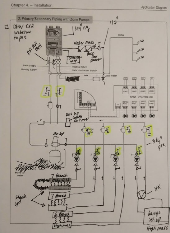
Best locations for drain valves

My "garage setup" would have a dedicated auto fill, backflow and pressure tank. Also would have a similar flush and fill valve location as the main diagram.
Note that all manifold stations have built in flush and fill valves, so I'm curious if I need as many as I'm planning in the diagram.
Thanks in advance for your input. The help is greatly appreciated.
Comments
-
Webstone has some options that may save you some valves. But isolating the circulators is always a good idea.
I'd put valves and threaded connections in to facilitate flushing/changing the heat exchanger for the garage.There was an error rendering this rich post.
1 -
Definately going to isolate the circultors. Do I need a drain valve on just one side or both? Absolutely on webstone.0
-
Fill or pressure reducing valves are best installed at the point of no pressure change . Which is the pipe between the expansion tank and the system ...
There was an error rendering this rich post.
0 -
I'd keep your make-up water entry point at the bottom of the microbubble air eliminator along with using the Webstone primary-secondary purge fitting. The combination allows you to purge the entire system and boiler from one point.


8.33 lbs./gal. x 60 min./hr. x 20°ΔT = 10,000 BTU's/hour
Two btu per sq ft for degree difference for a slab 1
1 -
Webstone discontinued the 1 1/2" x 1" purge valve 4 years ago. Part number H-58664. The boiler company recommends a primary loop of 1 1/2" x 1" for the secondary. In other words boiler side is 1" and system side is 1 1/2".I'd keep your make-up water entry point at the bottom of the microbubble air eliminator along with using the Webstone primary-secondary purge fitting. The combination allows you to purge the entire system and boiler from one point.
0 -
Planning on one of these, but didn't draw it in the digram. Will this in conjunction with the manifold flush and fill ports be a robust solution?Big Ed_4 said:Fill or pressure reducing valves are best installed at the point of no pressure change . Which is the pipe between the expansion tank and the system ...

0 -
"........... and system side is 1 1/2"."
So, your house is in the neighborhood of 6,000 square feet?
8.33 lbs./gal. x 60 min./hr. x 20°ΔT = 10,000 BTU's/hour
Two btu per sq ft for degree difference for a slab0 -
It's not. Based on my math 1 1/4" should be the size but the boiler companies prebuilt manifold is 1 1/2" (which I am only using as a guide to build my own)."........... and system side is 1 1/2"."
So, your house is in the neighborhood of 6,000 square feet?
Heated square feet total is ~ 5,000. Basement ~2,000, garage 1,200 and main floor 2,200.
The 1 1/2 covers the largest application the boiler can do. Hearing how fussy companies are with warranty I thought the safe bet is to go with what they pre-built manifold is. Additionally Idronics # 19 from Caleffi recommends "generously sized headers". I'm not entirely sure what this means alhtough my inerpritation is if the math says 1 1/4, upsize.
I've never done this before so appreciate the feedback. I'd prefer to go 1 1/4 as my component prices come down and I get to use the webstone valve above. My calculated system flow @ design condition is 10.7 gpm. According to this 1 1/4 would be the right choice.

0 -
It's nice to see all these questions from someone before all the work is done. You're on the right track!
If that were my job and the math worked out to 10.2 GPM, 1-1/4" for the secondary would be my choice.
P.S. That's a big house! My house would fit in your garage.8.33 lbs./gal. x 60 min./hr. x 20°ΔT = 10,000 BTU's/hour
Two btu per sq ft for degree difference for a slab 1
1 -
This project has felt like having another full time job. Between the installtion (staple up is not fun) and all the research it's been time consuming. There's a lot of cost on the line so I want to get this right.
Everyone has an opinion, but those that haven't spent the time to research don't really know. I've used the modern hydronic heating book by John Siegenthaler as well as Taco, Caleffi and Uponor information to arrive where I am.
I have good friend who was going to oversee the project however when I learned his staple up didn't touch the floor, have transfer plates and ran 180 degree water I decided I'd have to learn and do to make sure it was right.
Bless my wife, but even after explaining the math to her as a second resource she barely has a pulse and is in a comma it's difficult to get her out of. She does her best but for her this stuff is magic, but not the exciting kind.
Thanks for the input, I'm going to make the system loop 1 1/4".0 -
Got all the parts and I'm working on the install. Does the community have any concerns with the overall height my tridicator will be installed at? Adapting from 1 1/4 to 1/4" takes a pile of fittings and the probe isn't even close to the flow path of the tee.
Any concerns about an air bubble sitting in there?
0 -
It's a good idea to make the reduction as fast as possible.

https://www.supplyhouse.com/Elkhart-59217-1-1-4-x-1-1-4-x-1-2-CxCxF-Tee-Lead-Free
8.33 lbs./gal. x 60 min./hr. x 20°ΔT = 10,000 BTU's/hour
Two btu per sq ft for degree difference for a slab0 -
Looking for some group feedback. Trying to put all this stuff I've spent months researching together. It's fun and exciting but before I start soldering I'd like some input.
I'm curious how much close spaced tees matter in my system loop (loop supplying circulators) when I'm not trying to create hydraulic separation. Hopefully my terminology is correct. My circulators take "hot" water from the system loop and dump it into the return branch, not back into the hot loop like I've seen in many manuals. Looking to get some feedback as now is the time for me to get the correct if it actually matters.
Please excuse the pipe mess and my purple (supply) and blue (return) hand sketch over my current progress images. The diagram above is pretty close to what is in the photos.
Feel free to comment on component location of other things as well. There's two remote branch manifolds you can't see in the photos, ones for the garage with antifreeze mix (hence heat exchanger) and the other is for the 00e not connected to anything.0 -
Could I interest you in a Sep 4 instead of P/S? Time to move beyond primary secondary on many of these residential jobs
")
The sep give you 4 critical functions in one easy to pipe component. Microbubble air removal, particle down to 5 micron, hydraulic separation, and magnetic particle removal.
I'm not a huge fan of a valve between closely spaced tees. A full port valve can have the equivalent of 2' of pipe, reduced port valves 5'or more.Bob "hot rod" Rohr
trainer for Caleffi NA
Living the hydronic dream0 -
If I were a plumber and able to use all the purchased parts elsewhere possibly. Unfortunately it's all paid for and the cardboard boxes are gone (of course just last weekend
 ). Part of the reason I didn't settle on the sep 4 is warranty on the boiler. I followed closely the manual in hopes that if anything does malfunction with the boiler they will honor the warranty.
Possibly short sided on my part, especially since I've already spent as much as I have. Could've gotten the sep 4 for basically the same amount.
Thanks for the feedback:)0 -
@hot_rod
Knowing I'm stuck with all the parts, what would you recommend I do without having expensive paperweights? Scrap primary secondary and go small buffer tank?0 -
Quick update; manifolds in mechanical room close to being installed. A couple photos that are slightly cleaner to look at.
Curious on spacing of tees on system side of supply and return from my post above.
@hot_rod - also curious what my options are at this point knowing all parts are purchased? Buffer tank?schultzey11 said:Looking for some group feedback. Trying to put all this stuff I've spent months researching together. It's fun and exciting but before I start soldering I'd like some input.
I'm curious how much close spaced tees matter in my system loop (loop supplying circulators) when I'm not trying to create hydraulic separation. Hopefully my terminology is correct. My circulators take "hot" water from the system loop and dump it into the return branch, not back into the hot loop like I've seen in many manuals. Looking to get some feedback as now is the time for me to get the correct if it actually matters.
0 -
The only place you need the set of closely spaced tees is where the boiler connects into the distribution loop.
Personally I call the loop with the expansion tank the primary loop, so the boiler is a secondary as are the zones. Different opinions out there for which loop is which. Regardless...
The 3 way mix valves connect to the supply upper pipe left of the purger and expansion tank. The returns connect into the lower pipe.
You have what I call a horseshoe primary loop. The plate HX connections make it look like a rectangle loop. So the boiler injects heat energy into that loop, the various circulators pull out vis the mix valves.
No need for closely spaced tees for these S&R connection in and out of the distribution loop.
Maybe it is easier to visualize as a "moose antler loop
Bob "hot rod" Rohr
trainer for Caleffi NA
Living the hydronic dream0


Categories
- All Categories
- 87.7K THE MAIN WALL
- 3.3K A-C, Heat Pumps & Refrigeration
- 59 Biomass
- 430 Carbon Monoxide Awareness
- 127 Chimneys & Flues
- 2.2K Domestic Hot Water
- 5.9K Gas Heating
- 121 Geothermal
- 170 Indoor-Air Quality
- 3.8K Oil Heating
- 79 Pipe Deterioration
- 1K Plumbing
- 6.6K Radiant Heating
- 396 Solar
- 16K Strictly Steam
- 3.5K Thermostats and Controls
- 56 Water Quality
- 51 Industry Classes
- 51 Job Opportunities
- 17 Recall Announcements