Welcome! Here are the website rules, as well as some tips for using this forum.
Need to contact us? Visit https://heatinghelp.com/contact-us/.
Click here to Find a Contractor in your area.
If our community has helped you, please consider making a contribution to support this website. Thanks!
Replacing my Honeywell T6360B1028 for a digital version
Options

boredcol
Member Posts: 5
Hi there, im wanting to update my old thermostat to a digital version.
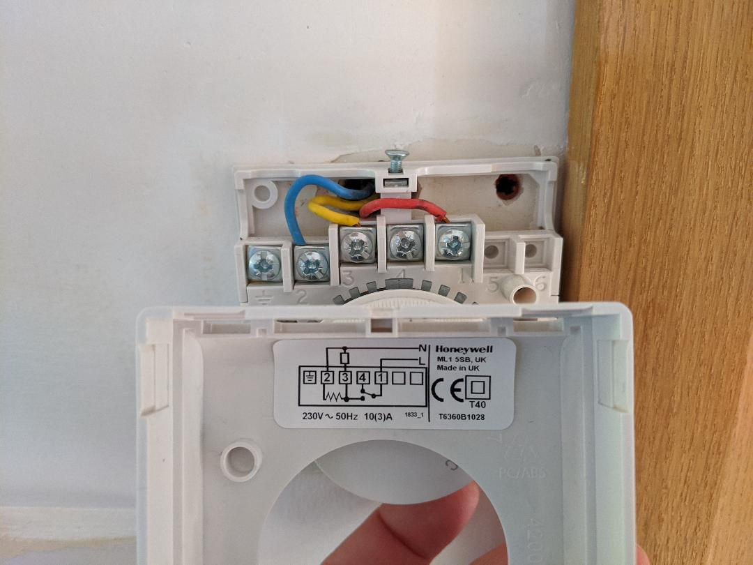
Ive included a photo so you can see the wiring i have currently running to the T6360B1028 on my wall at home.
The way mine is wired is :-
1 red
3 yellow
2 blue
The way i see it is:-
1 (red) is live
3 (yell) is sw live
2 (blu) is neutral.
However I have purchased a Salus RT500, that only has positions for Live and a SW live.
My question is what do I do with the neutral. Can i just put it on a choc block. Will it still work okay?
Or is the RT500 not suitable for this type of wiring, and i'll have to find one suitable for this configuration of wiring.
Thanks
0
Comments
-
Perhaps you can find a wiring diagram for your heating system. That might help.0
-
This is the controller I have EHE0200160 and I am guessing it is an S-Plan in my house, as i have 2 seperate zone valves, one for heating , one for hot water, and the S_Plan is the only one I see that has the 2 seperate valves.


0 -
How about the wiring diagram for the tstat?
0 -
Wiring diagram for the stat is in my 1st post, havent got any more info than that.0
-
The Neutral in the Honeywell is solely for the heat anticipator.
The RT500 needs the Neutral for the clock.
Terminal L- Red wire
Terminal N- Blue wire
Terminal 4- Yellow wire
L Normally Open to 4 will close on temperature drop.0 -
My RT500 does not have a slot for neutral as per pic. Only positions for live & SW live , I thought the clock was controlled by the batteries ?0
-
Ok. It's far different from the diagrams you posted.
You're dealing with 240v A/C, which we knew, but...
The old thermostat needed N (120v) to energize the heat anticipator.
The thermostats in the diagrams need N to power the clock.
Your new thermostat sub base as shown is just a switch. No N needed.
So you'll use the Red wire and Yellow wire. Cap the Blue.
I dont know the significance between L and SL. It shouldn't matter. If only there where directions for that exact thermostat.0 -
The new one with two wires as you stated above, not the installed one with three. Sorry for the confusion.0
-
Ok cheers for your help folks, I'll just put the unused neutral into a term block n give it a shot. Thanks again0


Categories
- All Categories
- 87.7K THE MAIN WALL
- 3.3K A-C, Heat Pumps & Refrigeration
- 59 Biomass
- 431 Carbon Monoxide Awareness
- 127 Chimneys & Flues
- 2.2K Domestic Hot Water
- 5.9K Gas Heating
- 121 Geothermal
- 170 Indoor-Air Quality
- 3.8K Oil Heating
- 79 Pipe Deterioration
- 1K Plumbing
- 6.6K Radiant Heating
- 396 Solar
- 16K Strictly Steam
- 3.5K Thermostats and Controls
- 56 Water Quality
- 51 Industry Classes
- 51 Job Opportunities
- 17 Recall Announcements