Welcome! Here are the website rules, as well as some tips for using this forum.
Need to contact us? Visit https://heatinghelp.com/contact-us/.
Click here to Find a Contractor in your area.
If our community has helped you, please consider making a contribution to support this website. Thanks!
Piping design--optimizing flow
Options

dave123
Member Posts: 67
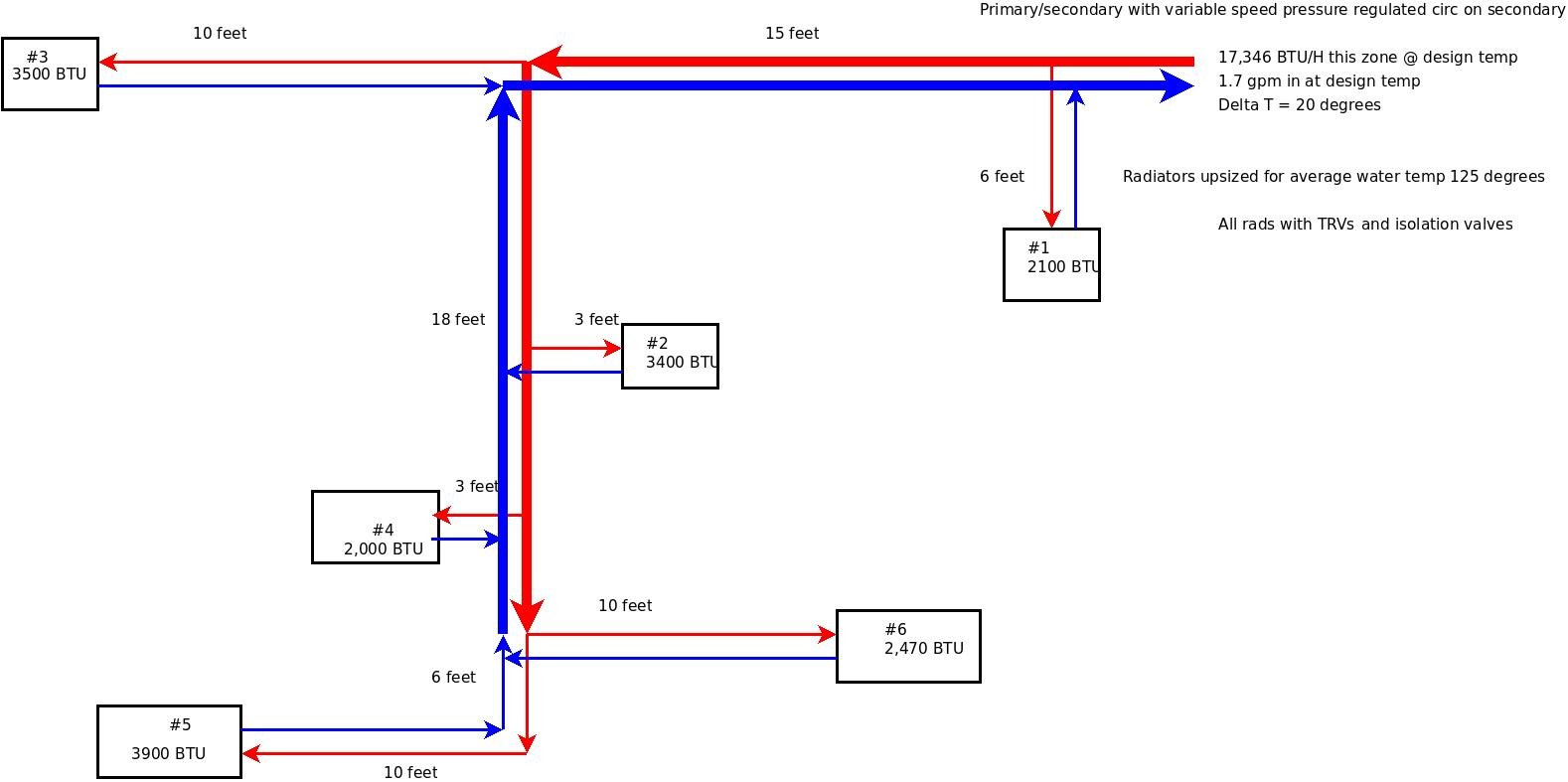
The attached drawing is my preliminary design for a single zone of a new two pipe system. With new oversized rads, an average water temp of 125 degrees, and delta T of 20 degrees, the flow rate in this zone at design temps is only 1.7 GPM. The required flow rates get really low as the pipes approach each individual rad.
Even 1/2 inch copper needs at least 1.6 GPM for a flow rate of 2 ft/sec. correct? So most or all of this zone will end up with flows much less than 2 ft/sec when the outside temp is higher than design temp.
So should I re-design using a delta T of only 10 instead of 20, and use a return water temp of 120 instead of 110, to get the flow rates higher?
0
Comments
-
If it were me...I would do a central manifold with 1/2 runs to each rad from the manifolds.1
-
Lower flow rates can be used when you aren't at design conditions since you don't need the full design output of the radiators. At the low flow rates, you do need to consider air removal, but you can do that with an ECM pump that can be run temporarily hard to purge air, then run slow under normal conditions.Hydronics inspired homeowner with self-designed high efficiency low temperature baseboard system and professionally installed mod-con boiler with indirect DHW. My system design thread: http://forum.heatinghelp.com/discussion/154385
System Photo: https://us.v-cdn.net/5021738/uploads/FileUpload/79/451e1f19a1e5b345e0951fbe1ff6ca.jpg0 -
I know this is commonly done, but I don't understand it. Single 1/2 inch pipes to each rad would need flows rates of approx 0.2 GPM for a delta T of 20 degrees at design temps. If they run faster, then the delta T has to drop, and return temps go up.delta T said:If it were me...I would do a central manifold with 1/2 runs to each rad from the manifolds.
What am I missing? Is the lower range of flow velocity of 2 ft/sec not really that important?0 -
This makes sense, but do you mean the system should then be purged with regularity, because of the low operating flows?Brewbeer said:Lower flow rates can be used when you aren't at design conditions since you don't need the full design output of the radiators. At the low flow rates, you do need to consider air removal, but you can do that with an ECM pump that can be run temporarily hard to purge air, then run slow under normal conditions.
Aren't tiny bits of air getting into the system all the time?0 -
Not if the system is tight. You should have good positive gauge pressure everywhere -- at least 5 psi even at the inlet to the pump and the highest points. Further, if there are no leaks, no makeup water (with dissolved air) is getting in. Should be OK.dave123 said:
This makes sense, but do you mean the system should then be purged with regularity, because of the low operating flows?Brewbeer said:Lower flow rates can be used when you aren't at design conditions since you don't need the full design output of the radiators. At the low flow rates, you do need to consider air removal, but you can do that with an ECM pump that can be run temporarily hard to purge air, then run slow under normal conditions.
Aren't tiny bits of air getting into the system all the time?
The problem with low flow rates, as has been noted, is purging -- but if you are piped and valved so that you can get the flow now and then as needed for maintenance, should be good to go.Br. Jamie, osb
Building superintendent/caretaker, 7200 sq. ft. historic house museum with dependencies in New England 1
1 -
Now I see. The rule is not necessarily 2-4 ft/sec all the time, but "greater than 2 ft/sec when needed for purging," yes?
So in my drawing of a zone up at the top, I could go with 3/4 inch pex for the main trunk ,and 1/2 inch pex for the individual rads, correct?
The reason I didn't want to home run is because a second zone composed of 8 rads needs to run across the ceiling of an unheated garage, and I want to minimize heat loss there from all the piping. The zone pictured above is over a heated basement, but I wanted to make the two zones similar in their piping.0 -
So, when all rads are in full operation the flow would be 1.7 gal/min, delivering 17,346 btu's/hr? ECM pump is a good match with TRV's, but how are you going to regulate the flow thru a rad when only one is working? An ECM pump will throttle down, but the flow rates seem to me to be disproportionate unless you have oversized headers since this is a parallel configuration instead of series.
I think I would use a manifold with balancing valves and pex lines to each rad with an ECM pump. Each rad should have a coin air vent to eliminate trapped air.
You would have more control over flow.
If you are using anti-freeze the btu's and the flow would would decline.
Oh, well, whada I know.0 -
Reverse return piping would help balance flow to all the rads.
Flow needs to drop pretty low in 1/2" before it runs laminar and heat transfer drops.
Idronics 16 can shed some light.
Bob "hot rod" Rohr
trainer for Caleffi NA
Living the hydronic dream0


Categories
- All Categories
- 87.6K THE MAIN WALL
- 3.3K A-C, Heat Pumps & Refrigeration
- 59 Biomass
- 430 Carbon Monoxide Awareness
- 124 Chimneys & Flues
- 2.2K Domestic Hot Water
- 5.9K Gas Heating
- 120 Geothermal
- 168 Indoor-Air Quality
- 3.8K Oil Heating
- 78 Pipe Deterioration
- 1K Plumbing
- 6.6K Radiant Heating
- 396 Solar
- 16K Strictly Steam
- 3.5K Thermostats and Controls
- 56 Water Quality
- 51 Industry Classes
- 51 Job Opportunities
- 18 Recall Announcements