Welcome! Here are the website rules, as well as some tips for using this forum.
Need to contact us? Visit https://heatinghelp.com/contact-us/.
Click here to Find a Contractor in your area.
If our community has helped you, please consider making a contribution to support this website. Thanks!
Re-Piping Old Radiators with PEX-AL-PEX
Options

GRIZ
Member Posts: 23
I have a 1500 sq ft house that is currently heated with large CI radiators, and appears to have been converted from a coal fired gravity system to a gas fired circulated system. I recently gutted a partially finished basesment, shored up and sealed the foundation, added a sump system, in preparation to refinish the basement into more useable space. In doing this I am adding a subfloor which now makes the old gravity feed lines a forehead busting hazard. So I began investigating moving the pipes into the joists. I had several plumbers come out and give their opinions about how it should be done, and I also have done quite a bit of research on line and in forums like this trying to determine the best way to get this done. Much of what the plumbers suggest seems to contrast the info I've read here, but after some prodding, most of them don't have much experience with this type of project. Based on this I think I have made the decision to take on this project myself, with the knowledge I've gained from research, hopefully along with some help from the experts here.
Here are some of the details to start with: My Boiler is a Weil-McLain CGr4-SPUN with 88,000 BTU Output Heating Capacity. My circulation pump is on the return side, and it is a Taco 007-BF4-JW. I also have a large galvanized expansion tank. There two a large (3”) CI supply and return lines feeding the system, and all of the radiators tee off of these lines (one to supply and one to return). There are 7 radiator runs out of the basement, 3 of these go to the 2nd story bedrooms (one of which tees off in the floor somewhere to split between one of the bedrooms and the bathroom), then there are 3 radiators in the dining/living area, and one in the cabinet under the kitchen sink. I estimated the EDR and Heating capacity for each radiator (using the method described here: http://www.columbiaheatingsupply.com/page_images/Sizing Cast Iron Radiator Heating Capacity Guide.pdf) and the capacities are as follows:
14960 BTU/Hr
12750 BTU/Hr
10200 BTU/Hr
8500 BTU/Hr
5100 BTU/Hr
7650 BTU/Hr & 5950 BTU/Hr (13600 together - these are the two that share a feed from the basement)
7140 BTU/Hr (This is the one under the sink).
Totaling 72,250 BTU/Hr for the entire system.
I’m planning to eliminate the radiator in the kitchen as it is only effectively heating the undersink cabinet while the rest of the kitchen remains pretty chilly. I’m exploring other heating sources for the kitchen, but that’s a topic for another day.
Some preliminary plans for this system. Demo all of the cast iron piping in the basement, and change to Pex-Al-Pex (probably the FostaPEX by Viega). Rather than run shared supply/return lines with a lot of tees, I plan to run individual supply and returns to each CI radiator from manifold at the boiler. This idea really appeals to me because it will allow me to balance the system from one location. Here is the manifold I was thinking of using https://www.supplyhouse.com/Viega-15906-8-Loop-ProRadiant-Stainless-Steel-Manifold-Shut-Off-Balancing-Flow-Meters. I plan to purchase an 8 loop manifold and only use 6 runs in case I decide at some point to add a run for a basement bedroom radiator or possibly somewhere else. I’d just cap the two unused runs at this point.
I also plan to replace my galvanized expansion tank with a newer bladder unit, but I’m not sure how to go about sizing that. I have also considered changing the circulation pump to and ECM pump, but I don’t know much about them. Taco makes a variable speed ECM pump that has a delta T sensing function that sound good in theory, but has some mixed reviews. See http://www.tacocomfort.com/products/variable_speed_products/vt2218/index.html. Several people have also suggested that I add a Spirovent air separator also, sounds like a good idea to me.
I am definitely not a pro when it comes to plumbing, but I’ve done a little here and there, and I’m a fast learner. I feel like I have a pretty good grasp of the situation, but perhaps I am overconfident….. I’m really looking for pointers or advice on any aspect that I may have overlooked in the process or anything in the above that looks suspect. As well as opinions and input on the FostaPEX, Manifold, ECM Pump, Expansion Tank and Spirovent. I have some specific questions too, but this is already turning into a novel so I will stop here for now and ask some questions as the discussion thread starts.
0
Comments
-
Depending upon the total length of supply and return run, you may have trouble getting enough gpm to the two larger rad's with 1/2" tubing. 5/8" would be sufficient and it may be more cost effective to do it all in that rather than buying different size rolls. That way, You can balance flow rates at the manifold.
We did it that way on one recently:
https://forum.heatinghelp.com/discussion/163504/gravity-system-boiler-replacement#latest
You need the Spirovent if you use a bladder tank, but whatever air gets by it will go to the top of the rads and have to be bled manually.
I'd also recommend that you thoroughly flush each rad/loop and add a dirt separator in the return line. Look at Caleffi's Sep4 or DirtMag.Bob Boan
You can choose to do what you want, but you cannot choose the consequences.-1 -
I will definitely add a dirt separator to the system, hadn't considered that before. I'm was planning to flush each rad/loop before finalizing the setup, as well, just hoping that I don't have too much sludge built up.
My two shortest runs are to the two largest rads, so that's a plus, but I definitely don't want to undersize it from the get go. Several of the plumbers that came in were planning to use 1" or 1-1/4" hePEX, but they weren't planning home runs. I have read that oversizing can cause issues too; if you get too much flow at the rads it doesn't give the heat time to dissapate. But the move from 1/2" to 5/8" sounds like it would add a little extra capacity just in case. Thanks for the advice!
I'm assuming the bladder tank is the only way to go anyway, right?
Thanks for the link to your recent post. That is very much what I have in mind and how I have pictured it in my head although I don't have near that much space to work with. The red units are circ pumps, correct? Is it standard practice to run a circ pump for each zone like this? I was thinking a single circ running to two zone valves, but individual pumps sound like they would be easier to control.
0 -
What does that almost 15000btu radiator look like? What kind of water temperature are you designing around to get that output?
I would be tempted to consider adding a panel rad or two (maybe on another 1/2" circuit) and keep using 1/2", (the bigger diameter you go with, the harder it is to work with), since the big rads are first floor maybe do a 3/4" copper floor penetration, and by then there may be so little length left than 1/2" would work without an excessive pressure drop.
You might get better comfort by running a outdoor reset mixing valve (taco i-series) and constant speed circulation rather than the delta T pump.
I'm not sure a delta T pump is the best fit for a system with a lot of parallel circuits (hard to hold a balance at different flows thru all the parallel circuits).
My opinion is that many houses have too many pumps/or are over pumped. My fav setup is variable primary, w/ zone valve's with a delta P ECM (either constant or proportional pressure depending on the application). You'll need a setup to protect your boiler from sustained condensing though. You can accomplish that with a the ODR Taco valve.
https://s3.amazonaws.com/s3.supplyhouse.com/manuals/1263218044528/23528_PROD_FILE.pdf
Are you considering some sort of hydraulic separator between the boiler and manifolds?
The Cadillac setup for you might be:- a mixing valve controlling temperature to the rads, with Outdoor reset/boiler protection. This will let you go lower in shoulder seasons without harming the boiler, you'll add comfort by having rads that are nice a warm (but not too warm) all the time instead of cycling at higher temperatures.
- a single Delta P pump serving the rads (lots to choose from)
- TRVs (non-electrical thermostatic valve) (lots to choose from) on each(most) rads
- On the primary side a boiler circ pump and a hydraulic separator
- maybe a mild outdoor reset on the boiler SWT to reduce losses from the piping and boiler.
-1 - a mixing valve controlling temperature to the rads, with Outdoor reset/boiler protection. This will let you go lower in shoulder seasons without harming the boiler, you'll add comfort by having rads that are nice a warm (but not too warm) all the time instead of cycling at higher temperatures.
-
@ Super J. The reference I used for the calculation of that output was http://www.columbiaheatingsupply.com/page_images/Sizing Cast Iron Radiator Heating Capacity Guide.pdf
This states that at 70 degree ambient room temp with 180 degree supply water, an average standing radiator heat emission will be approximately 170 BTU/SqFt of Surface Area for a hot water system. The largest "15,000 BTU" radiator has 4 columns per section, stands 22" tall, and consists of 22 sections. I don't have the exact length but I'm guessing it is roughly 6 ft long. It's a beast.
I'm confused about the "adding a panel radiator or two" portion of your comment. My house was built in 1915 and is mostly all original wood and finishes on the main level. I want to keep these radiators as much for the decor and character as the heating. Plus I love the heat they produce. I could certainly add panel radiators in the upstairs bedrooms, but I was hoping that just by putting them on a separate zone I should be able to increase their output slightly. By that I mean let them keep producing heat when ordinarily the stat on the first floor tends to shut down the system when the big rads heat up the main floor living area.
I had not considered a hyd seperator, but I am considering after reading about Ironmans suggestion about the Caleffi's Sep4 and reading about it. I understand the need for dirt and air removal, but I am still unclear on the need for hydraulic separation.
I haven't looked into mixing valves at all. In your cadillac scenario, am I right in reading that there are still 2 pumps? One supplying the radiators and one circulating at the boiler? I'm not familiar with what you are referring to as the primary side. I still have a lot to learn on the air/dirt/hydraulic seperators.
Regarding TRVs, I was thinking i would try to avoid these. While i will be replacing the valves on the larger lower level rads I haven't found the need to adjust them much. They are all basically in the same room so seperate TRV valves don't seem to makes sense to me. The central room thermostat seems to handle these pretty nicely. I'm trying to avoid any tampering with the radiator fittings upstairs. I'm planning to tie in the PEX-AL-PEX to the exisitng cast riser pipes to the second story and leave those original elements mostly in tact. I like the idea of two zones with a central themostat for each. The TRVs would make more sense in the bedrooms, but I'd like to avoid pulling spuds on 4 more rads if possible as this project continues to grow.
Thanks for the comments!
0 -
You’ve obviously put some though into this. You seem to have good reasons for you decisions.
If you are running two zones for the foreseeable future then pumping them separately might be the ticket (either that or a single secondary pump and zone valves). Use some sort of relay box to start the pumps/open the valve when the respective thermostat calls and give the boiler a demand signal.
With a hydraulic separator you would need a pump in addition to your zone setup to act as your primary boiler pump.
Still might want to consider some sort of low return temp protection. There are bunch of different ways to do this effectively. I think there are some coffee with Caleffi videos that deal with this.
It might be worth doing a heat loss calc to see if you actually need all that capacity from the big rads. Maybe you could get away with less flow.-1 -
Here is the original thread that got me going in this direction. There are a couple things I would do a little different, but this is very very similar to my application. https://forum.heatinghelp.com/discussion/154770/radiator-re-pipe-copper-or-pex0
-
If I stay with one zone for 6 loops with a single pump for the whole unit, I'm thinking there would be no need for a hyd sep, or zone valves, or mixing valves or ECM pump or any of that stuff. I'd still add an air seperator and dirtmag. I'm thinking that with all this other stuff I may be adding complexity I don't really need. The more I add to this system, them bigger chance there is that something doesn't work as planned. Since I'm still a newbie, I think I'll keep to the old adage KISS (keep it simple, stupid) and try not to get in over my head. I can always get creative down the road and reconfigure the near boiler stuff to add these components if I decide I need them. At some point I will probably need to replace the boiler which would be a good time to do a lot more with this system. My main goal for now is to replace the low hanging cast pipes with Pex-AL-Pex in a manifold/home run configuration and replace the expansion tank and still have a functioning heating system. I also think I am gonna roll with the 1/2" unless someones got some compelling reasons otherwise as FostaPex isn't offered in 5/8. I don't want to make the jump to 3/4 as I think it's going to be too difficult to work with. Anyone have compelling arguements to go with Uponor MLC over FostaPex? Other than MLC comes in 5/8" and is slightly cheaper?0
-
If you're going to cycle your boiler at 180F you may not need boiler protection, but you're leaving some comfort and control on the table if run that hot always.
https://www.pmmag.com/ext/resources/PM/2017/Nov-2017/Stay-above-the-dew-point-Siggy.pdf
Here's a good concept drawing for you.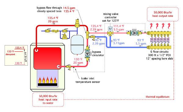
IMHO that job you referenced could benefit from a mixing valve for two reasons:
-Increase comfort by extending run/circulation times (lower temps equal longer run times and more even space conditions).
-Protect the boiler against harmful flue gas condensation (the 3 way valve has a boiler inlet sensor, outdoor temp sensor, and heating supply water sensor). It will throttle heating until the boiler return water is at a safe temperature, and then it will target a SWT that is reset off outdoor conditions.
You could keep the budget under control by using closely spaced Tee's instead of hydraulic separator. But some of the separators offer air/dirt/mag separation as well in one component. 1
1 -
When you say SWT, thats the supply water temp that feeds the rad?
How do I go about sizing the pump I need? I don't really know much about the flow rates required. I was thinking with the simplified system I know the circ pump I have has been feeding my 8 rads, while I am changing the size of the lines, I am also removing one of the rads, so I am reasonably confident the same pump will work without doing the math. (After writing out I suddenly feel like I should probably do the math).
Do you have any references to point me to for system design?0 -
Yes, meant the supply temperature to the radiators for SWT.
Here is the formula that many heating calcs are based off of:
BTU/hr = DeltaTx500xFlowRate
Delta T is generally degF
FlowRate is US GPM.
500 is a constant if you are using water, it changes slightly if you are using some sort of antifreeze.
So, if you know your heat output from the rad, 10000btu/hr for example, and your temperature delta you can solve for your flow rate.
In the document you linked to earlier it looked like you're designing around a 170degF average temperature. That likely means 180F in, 160F out for a 20degF delta.
10,000/(500x(180f-160f)) = 1GPM
Or (10 deg F delta at the same heat output or average water temp in rad)
10,000/(500x(175-165)) = 2 GPM
Once you have your flow requirements for each rad figured out, you can use piping pressure drop calculation charts (google) to figure out the pressure required to move the flow thru your worst case circuit. (don't forget to add up your flows and include the pressure drop of the supply and return piping and manifold).
If you end up needing 8gpm at 11fthd, make sure that point is within the capabilities of the pump you select by looking at the chart. If you go with a non-ecm pump you just choose a pump that is as close as possible (some are 3speed), you can fine tune your SWT if you're slightly over/under pumping.
There is hydronic design software to model and calculate this stuff for you, but doing it in a spreadsheet isn't too bad.
Keep in mind you calculated the output of the rads at 170degF, you may not need the full capability of the rads if you've improved the construction of the home. This may mean you need a little less flow.0 -
Based on the heat specs on the PAP, I'm thinking 180 may be a little high for a design temp, plus those rads would be pretty hot, right? I don't think its running that hot now as they are usually comfortably warm to the touch. Might be best to target something a little lower like 160-140? I know that I would need to do a heat loss calc and see if I can get the BTUs I need at that temp. Maybe that's the reason for the larger rads?
How do I go about calculating/estimating the pressure drop for the rads?
I've been playing around with the Taco Design Software. It looks pretty powerful, but would probably take me longer to figure out how to run the software effectively than it would to just do the calcs in a spreadsheet.0 -
Sounds like you are running at lower than 170F avg temps you initial numbers were based on. It would helpful to figure out what your current actual max operating temperature is and recalculate your EDR based on the average of your actual SWT and RWT temperatures. That will give you a better idea of what the actual required heat output per rad is to maintain your current level of comfort. You can then work backwards to a flow based on that revised BTU per rad number. Then you can figure out your pressure drops.
To calculate pressure drops, the pressure drop within the rads won't be too much typically. Since the ports are big and the flow is relatively unencumbered. The distribution piping is probably where your pressure drop is going to sneak up on you. Manufacturers post charts of pressure drops in their tubing, manifolds, boilers, etc. Use a spreadsheet to table the pressure drop based on the flowrate thru each device.
Keep in mind you can't really make up for a temperature reduction in flow, it's a losing battle, as more flow only adds incrementally more capacity. At 160F (150f avg), you will get about 73% of the heat as at 180F (170f avg).
180F is considered to be the max for PEX piping. Maybe some others can chime in on their opinions of using PEX at high temps.
You can use an outdoor temperature reset control to bring the water temperature down a bit as it gets warmer outside. So it will only be at max temps for hours each year instead of constantly.
Can you post some pictures of your system? and maybe a table of estimated supply and return piping distances to each rad? Estimate on supply and return piping to your manifold and pipe size.
You might be able to vent your kitchen undersink cabinet to get some output from the rad. Some vents at the top and bottom (none in the middle) will allow natural convection to occur even if the rad is fairly blocked off. See this article. https://heatinghelp.com/heating-museum/radiator-enclosures/
0 -

This is the arrangement I am currently planning to go with. After some demo I determined that there was some flue gas condensation occurring and it does indeed need protection. The outdoor reset valve is interesting, but when the outdoor temp reaches 70 degrees my heating system is typically shut down for the winter anyway. The complexity of these systems and cost seems to outweigh the value to me. The system above is detailed in the Weil Mclain boiler manual, and it describes how to balance the system by manipulating valves 7a and 7b.
Question, since I am only using one thermostat to control the entire system, would it be deemed acceptable to run the secondary circ pump off of the boiler transformer along with the primary circ pump?0


Categories
- All Categories
- 87.6K THE MAIN WALL
- 3.3K A-C, Heat Pumps & Refrigeration
- 59 Biomass
- 430 Carbon Monoxide Awareness
- 124 Chimneys & Flues
- 2.2K Domestic Hot Water
- 5.9K Gas Heating
- 120 Geothermal
- 168 Indoor-Air Quality
- 3.8K Oil Heating
- 78 Pipe Deterioration
- 1K Plumbing
- 6.6K Radiant Heating
- 396 Solar
- 16K Strictly Steam
- 3.5K Thermostats and Controls
- 56 Water Quality
- 51 Industry Classes
- 51 Job Opportunities
- 18 Recall Announcements