Can I upgrade to wifi thermostat with this aquastat?

Where would I attach a common wire which all wifi thermostat need?
would I be able to (or need to) use any of the other conductors?
Separately-is the wire that is just hanging there a ground? I need a ground for my circulator pump as it is plastic and the BX ground is useless I think.
Thanks for the help. I have a couple other threads showing the little upgrade I have made to this boiler. your help is appreciated.

this is a pic of the working side of the boiler.

Comments
-
I don't know of any aquastat that offers a common terminal. That aquastat does not either. The W,B,R terminals are SPDT (single pole, double throw) relay contacts.
R-B opens, R-W closes on temperature rise.
If you want to invest some $, you can get a new Hydrostat aquastat and a 2 or 3 zone, zone control board. The transformer in the zone board will offer a common. Maybe a well if you want LWCO protection. The aquastat will also give you a Boiler Reset economizer.
Check out the Hydrostat and let us know if your interested, then we can lay it out.
If you don't want the Hydrostat, you can leave that aquastat and move the circ and tstat wires to the zone board.
BTW, can you find out where the red wire on terminal 4 goes, and post some pics of the burner compartment?0 -
It's not uncommon for the common side if the low voltage transformer to be connected to the case. A quick test would be to throw a multimeter between the stat terminals (one at a time) to ground, with the thermostat turned off. If you see 24vac between jusst one terminal and ground, that terminal is the hot and the ground can be used as a common for the stat.
 0
0 -
> @ratio said:
> It's not uncommon for the common side if the low voltage transformer to be connected to the case. A quick test would be to throw a multimeter between the stat terminals (one at a time) to ground, with the thermostat turned off. If you see 24vac between jusst one terminal and ground, that terminal is the hot and the ground can be used as a common for the stat.
The internals of the aquastat relay actually uses the common on the transformer to complete the circuit through the thermostat. 24v goes to one side of the relay coil.
You'll get a 24v reading across TT when the thermostat is open because 24v is flowing through the unenergized coil.
You can't complete a 24v circuit with that aquastat.0 -
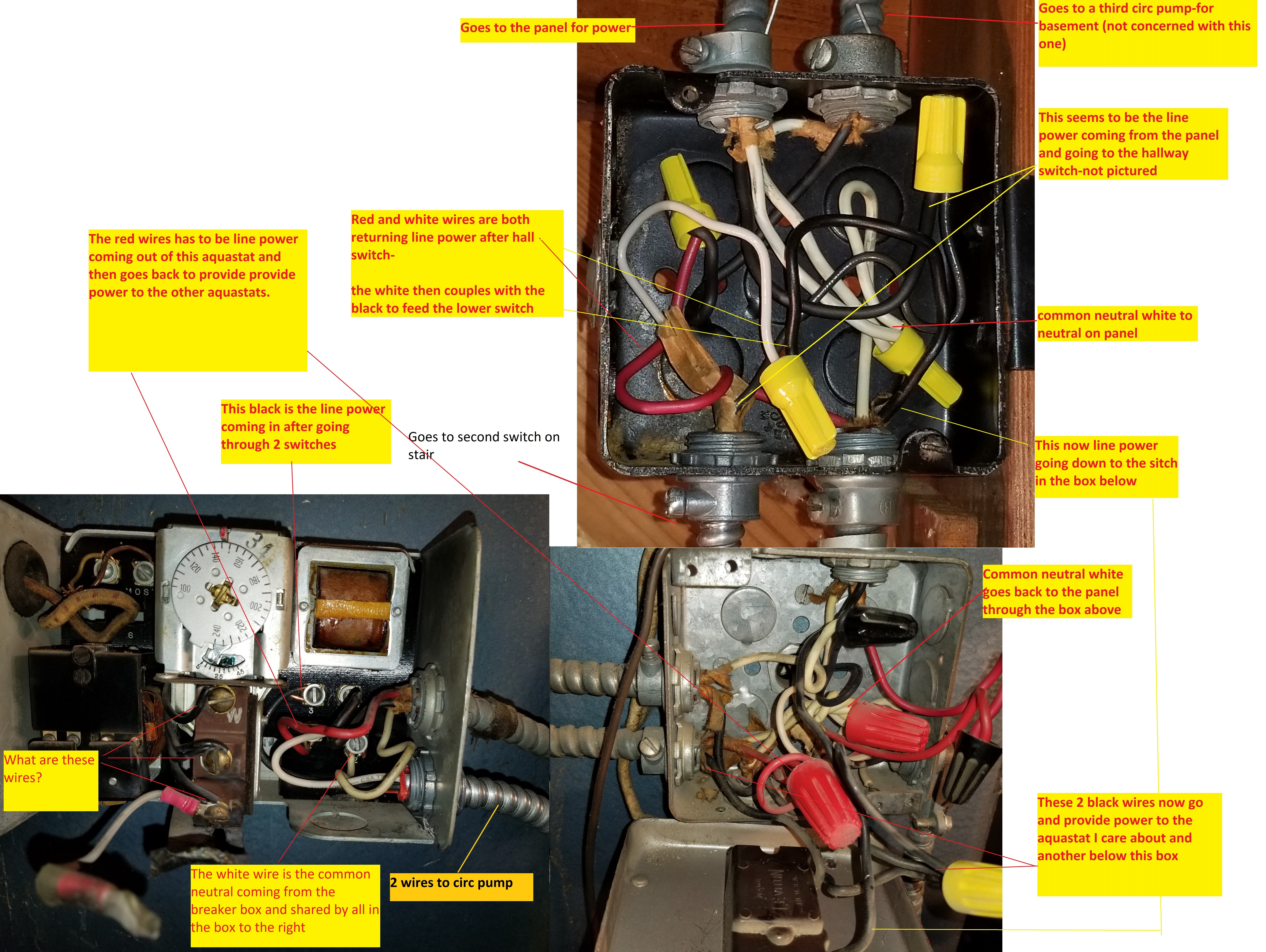
Here is a map of the electrics of my boiler. The red wire is line power leaving the aquastat to provide power to the next aquastat in the line like a duplex outlet passes through current for the circuit. There is a common white. why could I not use that? Ir why could I not pigtail a transformer of the line power in this aquastat and common to a 24v and then use that to provide power and common to a wifi stat in do so dropping the voltage and still having it on the same circuit?
0 -
@HVACNUT, right, you need to check voltage from the screw terminals to ground/chassis/enclosure. I was afraid that might come out unclear. One of the screws (may) show 24 volts to ground always, the other will show either ~zero volts to ground (when the stat is NOT calling) or 24 volts to ground when the thermostat IS calling. The terminal that shows 24 vac always is R, the other is W.
@jjustinia11, the BX (armored cable, fat wires) is most likely line voltage, 120ish volts. There is at least one stat wire (24 vac low volt) which I'm assuming feeds your thermostat, the low voltage common is NOT the same as the line voltage common, even if they are at the same potential. It's slightly 'not right' to use the ground as the low voltage common, but it's bad news to mix low voltage and line voltage.
0 -
Yes, the thermostat wires are coming in on the upper left -right next to the temp setting dial (unlabeled) Yes the line wires are definitely 120VAC. what are the wire in the middle? and why could I not drop (pigtail) a line off the 120VAC and put a transformer on it and drop it to 24V (just like they do for doorbells)?ratio said:@HVACNUT, right, you need to check voltage from the screw terminals to ground/chassis/enclosure. I was afraid that might come out unclear. One of the screws (may) show 24 volts to ground always, the other will show either ~zero volts to ground (when the stat is NOT calling) or 24 volts to ground when the thermostat IS calling. The terminal that shows 24 vac always is R, the other is W.
@jjustinia11, the BX (armored cable, fat wires) is most likely line voltage, 120ish volts. There is at least one stat wire (24 vac low volt) which I'm assuming feeds your thermostat, the low voltage common is NOT the same as the line voltage common, even if they are at the same potential. It's slight 'not right' to use the ground as the low voltage common, but it's bad news to mix low voltage and line voltage.
ALSO-could I not just buy a new aquastat the would replace this one with the same wiring which would have a 24v common? just do an even swap of aquastats (nothing fancy and not having to do anything with the other zones?)?0 -
Yes the BX line is 120 VAC.ratio said:@HVACNUT, right, you need to check voltage from the screw terminals to ground/chassis/enclosure. I was afraid that might come out unclear. One of the screws (may) show 24 volts to ground always, the other will show either ~zero volts to ground (when the stat is NOT calling) or 24 volts to ground when the thermostat IS calling. The terminal that shows 24 vac always is R, the other is W.
@jjustinia11, the BX (armored cable, fat wires) is most likely line voltage, 120ish volts. There is at least one stat wire (24 vac low volt) which I'm assuming feeds your thermostat, the low voltage common is NOT the same as the line voltage common, even if they are at the same potential. It's slightly 'not right' to use the ground as the low voltage common, but it's bad news to mix low voltage and line voltage.
Yes the thermostat wires are the ones in the upper left immediately to the left of the temp dial.- What are the 3 wires/terminals in the middle
- Why could I not drop a pigtail off the 120VAC line and take it to 24v transformer (just like they do for doorbells) and use that for the common 24v wires?
- ALSO-could I not just buy a new aquastat with the same wiring as I currently have (so I dont have to rewire the whole thing differently) but that would have a common 24V wire/terminal. and then just do an even swap of the existing aquastat with a newer model and not get fancy and just deal with this zone and leave the other zones as they are?
0 - What are the 3 wires/terminals in the middle
-
1) IDK. I'll try and look up a schematic/manual for that aquastat but it's pretty certain that none of them are a low voltage common.
2) The line voltage common is not the same as the low voltage common. The low voltage common must come from the secondary of the transformer. They may be electrically connected. If you use the line voltage common to feed the stat, you are dependant on it a) existing and b) never going away for any reason, intentional or unintentional. The results range from nothing to a house fire. Please don't do it. (The transformer itself already has the line voltage common going to it, that's the other wire of the circuit that powers it)
3) I don't know if you could find an exact replacement that provides a C term. A zone board may provide a low voltage common, but I'm unable to recommend one—I don't work with them often. @HVACNUT seems to have some experience with this. Perhaps he could suggest something.
Actually, I just reread what he said about that particular aquastat, it seems this model uses low side switching, making it particularly difficult to use in the way you desire.
Perhaps a different approach will prove successful. What thermostat do you plan on using? Most/all thermostats that have a separate R(heat) and R(cool) use the cooling side as the stat power. If that's the case with your new stat, simply add a 24vac transformer (powered continuously from a convenient source) tied in to the Rc and common, landing the existing stat wires on the Rh and W, and removing any jumper that connects Rh to Rc as per the instructions. That will power the thermostat yet allow it to independently switch the heat.
1 -
Thanks-to clarify on 2 could I not drop the line and neutral to the 24v transformer to provide power to the wifi stat?ratio said:1) IDK. I'll try and look up a schematic/manual for that aquastat but it's pretty certain that none of them are a low voltage common.
2) The line voltage common is not the same as the low voltage common. The low voltage common must come from the secondary of the transformer. They may be electrically connected. If you use the line voltage common to feed the stat, you are dependant on it a) existing and b) never going away for any reason, intentional or unintentional. The results range from nothing to a house fire. Please don't do it. (The transformer itself already has the line voltage common going to it, that's the other wire of the circuit that powers it)
3) I don't know if you could find an exact replacement that provides a C term. A zone board may provide a low voltage common, but I'm unable to recommend one—I don't work with them often. @HVACNUT seems to have some experience with this. Perhaps he could suggest something.
Actually, I just reread what he said about that particular aquastat, it seems this model uses low side switching, making it particularly difficult to use in the way you desire.
Perhaps a different approach will prove successful. What thermostat do you plan on using? Most/all thermostats that have a separate R(heat) and R(cool) use the cooling side as the stat power. If that's the case with your new stat, simply add a 24vac transformer (powered continuously from a convenient source) tied in to the Rc and common, landing the existing stat wires on the Rh and W, and removing any jumper that connects Rh to Rc as per the instructions. That will power the thermostat yet allow it to independently switch the heat.
And I think that maybe on 3-that is what you are saying??? I would like to do what @HVACNUT suggests but need a little more guidance, like pointing me at what aquastat and products to use and then I could look at them and learn what needs to happen.
thank you!
0 -
I'll defer to HVACNUT re the aquastat, but what I'm thinking might be your best option would be (IF your new Wi-Fi thermostat has separate Rc and Rh, i.e. two power terminals, one for heating and one for cooling) to use two conductors to provide power to the thermostat on the Rc and C terminals and two to control the heating system via the Rh and W terminals. The manual to the stat should tell you if that is possible. The 24 volt power can be provided from an additional transformer mounted somewhere that provides continuous power.0
-
@jjustinia11. I think, but not 100% sure, like @ratio said, there are no Aquastats for you application that provide a low volt common. The reason being that the transformer in the aquastat can't handle more of a load than the current through a non powered thermostat.
The three terminals R,W,B are part of the Aquastats dual function.
"R" being common, R-B opens on temperature rise, R-W closes on temperature rise. Currently that aquastat is set to 140. If you raise the heat for the new circ, that circ should shut down if the boiler temp drops below 140. That's why it was set to 0 originally. That aquastat is used when a boiler has a tankless coil as yours does. The purpose is to shut down the circ before boiler temp gets so low you won't have domestic hot water.
I know my suggestion might be a little pricey, but it's a better set up and does other functions.
I'll post back, but now The Walking Dead is on.0 -
@jjustinia11, is there a cover for the aquastat? If so, is there a wiring diagram you can post? Maybe you can do without a new aquastat.0
-
Thank you. I am processing what you just wrote. Did some searching and yeah each of those items are pricey when added together.HVACNUT said:@jjustinia11. I think, but not 100% sure, like @ratio said, there are no Aquastats for you application that provide a low volt common. The reason being that the transformer in the aquastat can't handle more of a load than the current through a non powered thermostat.
The three terminals R,W,B are part of the Aquastats dual function.
"R" being common, R-B opens on temperature rise, R-W closes on temperature rise. Currently that aquastat is set to 140. If you raise the heat for the new circ, that circ should shut down if the boiler temp drops below 140. That's why it was set to 0 originally. That aquastat is used when a boiler has a tankless coil as yours does. The purpose is to shut down the circ before boiler temp gets so low you won't have domestic hot water.
I know my suggestion might be a little pricey, but it's a better set up and does other functions.
I'll post back, but now The Walking Dead is on.
Humor me and look at this. Why could I not just use this to get 24 volt power to the modern WiFi stat. I would get a 24v hot and neutral for the stat, no fire isssues...
https://amazon.com/Honeywell-AT72D1683-120V-24V-Transformer/dp/B000692A58
Enjoy the show! I agree I did research and what you suggest has lots of benefits, but would I be over doing it on the old boiler, and if it craps out I would have wasted that large price tag for the hydrostatic and zone control board...
Also, seems like you connected why my aquastat was at zero, I did not understand what you saw. I have it set to 145 now, is that going to cause a problem? Should I put it back to zero? I thought that would just make my pump go all the time and wear it out. As you know I have a 50gallon hot water heater on the other side of the boiler and the boiler coils water goes to the hot water heater after, nice and hot, so thinking that is an energy savings...is that correct thinking?
This is the cover to my aquastat:
0 -
My last post disappeared. super annoying, I wrote a lot.HVACNUT said:@jjustinia11, is there a cover for the aquastat? If so, is there a wiring diagram you can post? Maybe you can do without a new aquastat.
- Do you think I could just use this transformer? https://amazon.com/Honeywell-AT72D1683-120V-24V-Transformer/dp/B000692A58
- I would have a 24 volt hot and a neutral
- this is a quote from the amazon comment section about this transformer: "Like most on here, I needed to add a C wire, and this plus an isolation relay allowed me to retrofit my older control unit. Well-built, no hum, and an easy install." AND "As long as you can tap the 24v off the boiler transformer and direct it via wire to the thermostat, that will provide the necessary electric for the thermostat."
- I did NOT understand what you did about having the aquastat at zero. I have it at 145, I thought having it at zero would mean the circ would run constantly and wear it out? should I put the temp back to zero? you know I have a 50-gallon hot water heater, my thinking was that the coil would send hot water to the hot water heater reducing the work for the hot water heater and save me some money.
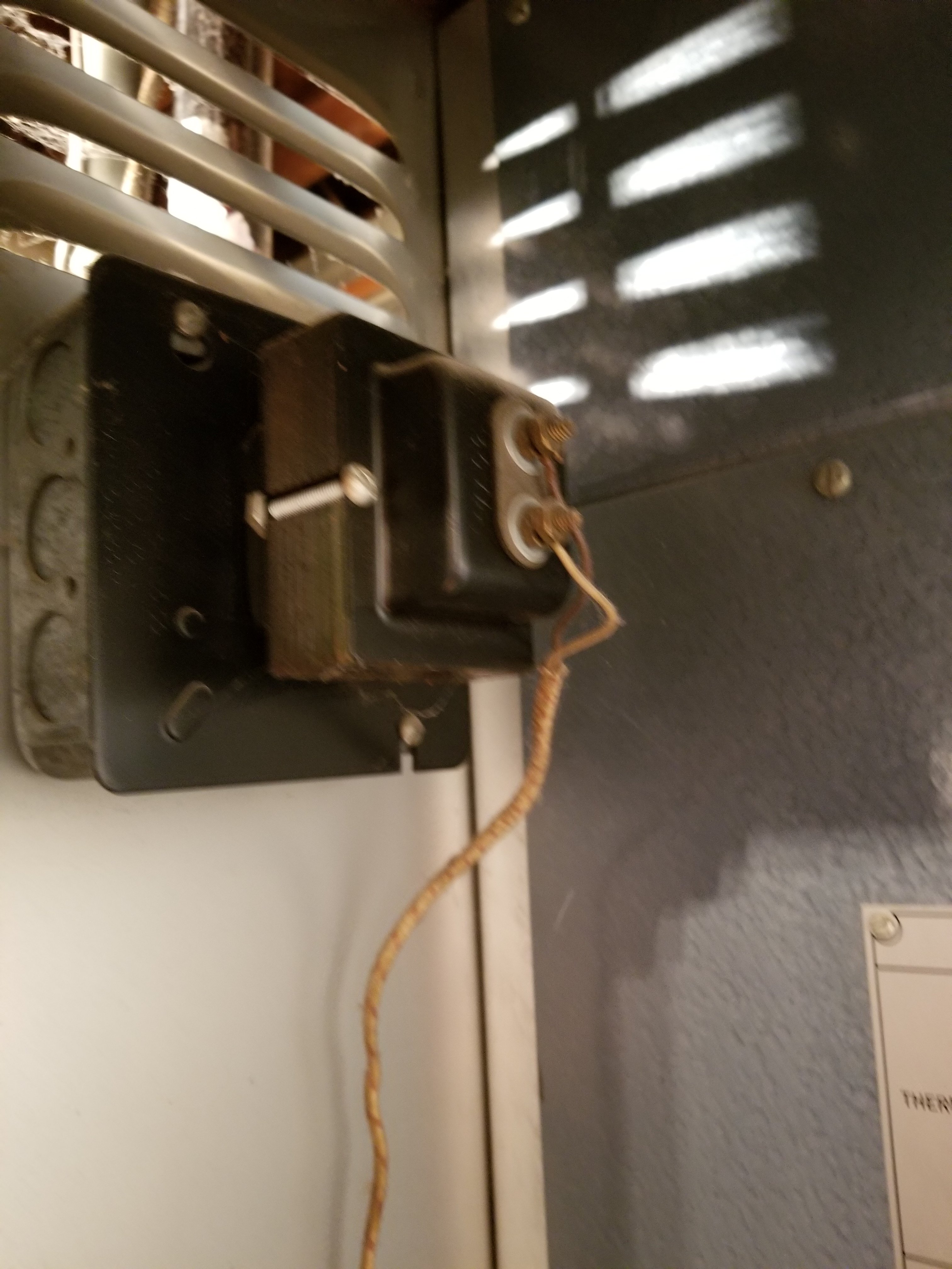
- here is a pic of the back of my aquastat:

0 - Do you think I could just use this transformer? https://amazon.com/Honeywell-AT72D1683-120V-24V-Transformer/dp/B000692A58
-
I also see that I was wrong about the red wire. That wire come from a transformer inside the boiler. The wire comes out of the boiler then goes to the Ritchie hot water stat and comes back out and is joined to this red wire and others that go to each other aquastat. So it is obviously the switch from the boiler telling the stats to Turn on at a certain temp and telling the boiler to fire.0
-
I knew something wasn't right with that red wire. It should also gi through the white Rodgers high limit.
Can you post a pic of inside the burner cabinet?0 -
The transformer you mentioned above (your link doesn't work) is part of my suggested workaround. If your new thermostat has the two separate R terminals you can do it directly, if it has only one R terminal you'll need the relay mentioned in the Amazon review. The new transformer can be powered from terminals 1 & 2 in the aquastat.
Have you picked out which WiFi thermostat you want to use? We could make more concrete suggestions if we knew that detail.
0 -
-
Sure, when I get home, but you are correct. When I wrote Ritchie I meant white Rodgers. I got lazy. Neutral goes from the transformer on the inside of boiler to the common neutrals. The black come out and traverses to the white Rodgers, returns as a white and combines with the red wire you see on the Aquastat. On the inside of the boiler 2 low voltage wires go to the gas and burner stuff gernerally speaking.HVACNUT said:I knew something wasn't right with that red wire. It should also gi through the white Rodgers high limit.
Can you post a pic of inside the burner cabinet?
This is the tansformer was looking at:
https://www.amazon.com/Honeywell-AT72D1683-120V-24V-Transformer/dp/B000692A58
https://amazon.com/Honeywell-AT72D1683-120V-24V-Transformer/dp/B000692A580 -
YES! the top image is exactly what I was thinking. You can use any hot wire with constant 120VAC correct?ratio said:See if this helps any
The bottom one with the relay is less ideal as I really dont understand the way the relay works. but in either instance power is stepped down to 24V via a transformer and that is cheap to do. I see the trick is getting a stat where the r and rc terminal can be separate. Correct?
0 -
To feed the transformer yes, any constant hot will work. The hot & neutral that feed the aquastat would be ideal (terminals 1-> hot & 2-> neutral), but anything that's not switched (like the power to the circulator or burner) will work.
That diagram shows the back terminals of a Honeywell TH8321WF, which I'm familiar with. Any wifi stat that a) has separate R terminals and b) powers itself from the cooling R will work. The reason is the necessary isolation between the new power going to the thermostat and the existing power coming from the aquastat.
The lower schematic shows an additional relay that provides the required isolation. With that one, basically the thermostat turns on the relay and the relay turns on the aquastat.
0 -
Yes, you would split the hot and neutral that feed the aquastat and have one set keep going to the aquastat and their going to the transformer. But actually, I might tap the line in the upper box before any of the switches so the emergency shut-offs don't turn off the wifi thermostat.ratio said:To feed the transformer yes, any constant hot will work. The hot & neutral that feed the aquastat would be ideal (terminals 1-> hot & 2-> neutral), but anything that's not switched (like the power to the circulator or burner) will work.
That diagram shows the back terminals of a Honeywell TH8321WF, which I'm familiar with. Any wifi stat that a) has separate R terminals and b) powers itself from the cooling R will work. The reason is the necessary isolation between the new power going to the thermostat and the existing power coming from the aquastat.
The lower schematic shows an additional relay that provides the required isolation. With that one, basically the thermostat turns on the relay and the relay turns on the aquastat.
Is it that simple?
0 -
Yes.0
-
@HVACNUT Here are some pics of the inside of the boiler. Please tell me what you think of this and what you think of the plan to just use a transformer or if there is a benefit to another strategy. Thank you,HVACNUT said:I knew something wasn't right with that red wire. It should also gi through the white Rodgers high limit.
Can you post a pic of inside the burner cabinet?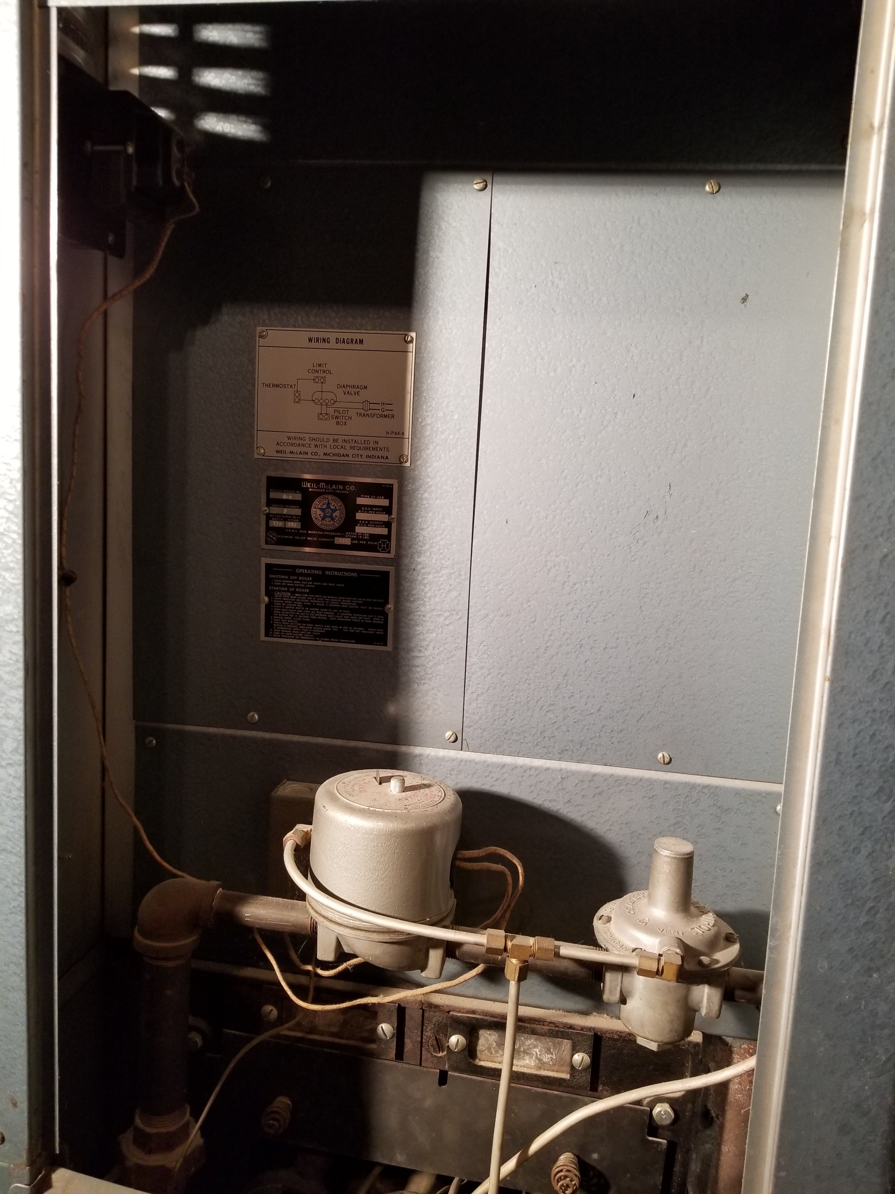

0 -
> @jjustinia11 said:
>
> @HVACNUT Here are some pics of the inside of the boiler. Please tell me what you think of this and what you think of the plan to just use a transformer or if there is a benefit to another strategy. Thank you,
There's your transformer in the last pic. You can go right off of that.
But since that one looks older than dirt, I would replace it with a new one.
40va with an inline 3 amp fuse. 2
2 -
Doesnt that transformer fo on and off as the boiler is turned on and off by the white ritchie?HVACNUT said:> @jjustinia11 said:
>
> @HVACNUT Here are some pics of the inside of the boiler. Please tell me what you think of this and what you think of the plan to just use a transformer or if there is a benefit to another strategy. Thank you,
There's your transformer in the last pic. You can go right off of that.
But since that one looks older than dirt, I would replace it with a new one.
40va with an inline 3 amp fuse.
0 -
jjustinia11 said:
Doesnt that transformer fo on and off as the boiler is turned on and off by the white ritchie? Also is the stat 24V or 40V . I thought I should match voltage?HVACNUT said:> @jjustinia11 said:
>
> @HVACNUT Here are some pics of the inside of the boiler. Please tell me what you think of this and what you think of the plan to just use a transformer or if there is a benefit to another strategy. Thank you,
There's your transformer in the last pic. You can go right off of that.
But since that one looks older than dirt, I would replace it with a new one.
40va with an inline 3 amp fuse.0 -
40VA, 40 volt-amps. A measure of power. The voltage output is 24 volts. I didn't trace out the diagram to see if the transformer is itself switched on & off. If that's not the case then it can't be used, but it'll save you some $$$ if it can be.1
-
Is there a way I can test to see if it is being switched. Use a voltmeter when its not burning.ratio said:40VA, 40 volt-amps. A measure of power. The voltage output is 24 volts. I didn't trace out the diagram to see if the transformer is itself switched on & off. If that's not the case then it can't be used, but it'll save you some $$$ if it can be.
0 -
jjustinia11 said:
Is there a way I can test to see if it is being switched. Use a voltmeter when its not burning.
That's exactly it. From screw terminal to screw terminal. You should show 24 volts nominal, which means probably closer to 26-27 volts with the burner off. Make sure you're on an AC range, 50 volts or higher if your meter isn't auto ranging. You might need to poke & wiggle the probes on there a little to cut through the dirt.
1 -
@jjustinia11. I may have been mistaken on you being able to use that transformer inside the burner cabinet.
It's really hard to figure the wiring sequence from pics, but I think that transformer is only energized on a heat call.
All the control wiring seems to be line voltage and the burner circuit is 115v to power the transformer, sending 24v to the gas valve. So if there's no heat demand, the transformer will not be live.
Sorry it took me so long to respond.-1 -
Can I screw a 1 gang metal box on the side of the boiler near the aquastat for the transformer? there seems to be a space between the outer sheet and the inside. If I us a tiny metal screw would that work. trying to get the transformer close to the aquastat.
Thanks!0 -
Should be fine, although as a washed-up electrician I'd use a 4 square box. More room inside. There are actually restrictions on how many conductors you can put in a handy box, although a transformer & it's feeders might be acceptable.1
-
Thanks!ratio said:Should be fine, although as a washed-up electrician I'd use a 4 square box. More room inside. There are actually restrictions on how many conductors you can put in a handy box, although a transformer & it's feeders might be acceptable.
yeah, only putting one conductor in and a transformer on the outside. There is little room on the side where it is not under a water pipe and close enough to the aquastat that I dont have to start splicing thermostat wires (that would be a pain). Smallest screws I could find were self-tapping #10 x 1/2in. Hoping they don't hit the cast iron.0 -
That should be fine.1
-
Does this look kosher? I tested the common and low voltage power line where the new thermostat will go and it came out to about 27volts. I believe that is normal because there is no load on it. This was the only location I could get the transformer in, I wanted it above the pipes in case of a water leak. Obviously, I will be putting the cover back on the aquastat, just have it off for the pics. I was going to wrap the low voltage wires with some electrical tape or maybe some shrink tubing??? thoughts?
Seems good to go, I am just patching the wall and repainting it because the new stat is smaller. so should go in tomorrow or Saturday. I just have the old stat hanging from the new wires and capped the new low voltage wires until ready to use while I repair the wall.

0 -
Looks fine. It's not necessary to cover the low voltage wire other than for asthetics.
Good job!
-1 -
Done.

0
Categories
- All Categories
- 87.7K THE MAIN WALL
- 3.3K A-C, Heat Pumps & Refrigeration
- 59 Biomass
- 430 Carbon Monoxide Awareness
- 128 Chimneys & Flues
- 2.2K Domestic Hot Water
- 5.9K Gas Heating
- 121 Geothermal
- 170 Indoor-Air Quality
- 3.8K Oil Heating
- 79 Pipe Deterioration
- 1.1K Plumbing
- 6.6K Radiant Heating
- 396 Solar
- 16K Strictly Steam
- 3.5K Thermostats and Controls
- 56 Water Quality
- 51 Industry Classes
- 51 Job Opportunities
- 17 Recall Announcements