Welcome! Here are the website rules, as well as some tips for using this forum.
Need to contact us? Visit https://heatinghelp.com/contact-us/.
Click here to Find a Contractor in your area.
If our community has helped you, please consider making a contribution to support this website. Thanks!
Looking for confirmation on a DIY Installation
Options

ccirou3
Member Posts: 8
Hi all!
Newbie here, apologies in advance for my lack of expertise. Your site has been invaluable to me while I attempt to become an amateur internet plumber in order to build out my radiant system (don't worry I'm not installing it myself). There's so much internet advice and there's not always a unanimous consensus on the way to do things. Here's the details of my set up:
Location: Atlanta
Zones: 2 (4 loops in the slab downstairs, 4 loops stapled up to the second floor, with plates)
Boiler: Navien NCB 150E. I also purchased the Navien Primary Manifold
Here's my amateur drawing:

Couple questions on my mind:
- What am I missing? Do I need a better way to purge beyond what the pre-assembled primary loop provides? Maybe for each zone? Where should I insert that if need be?
- Upstairs, there is 1 loop that did not quite make it to 300ft. It's more like 200ft. Do I need a flow meter on all the loops in that zone to correct that, or just the short loop? Or do I need to be worried about that at all?
- Any issues foreseen with using Ecobee thermostats?
Any advice would be welcome! Thanks!!
Newbie here, apologies in advance for my lack of expertise. Your site has been invaluable to me while I attempt to become an amateur internet plumber in order to build out my radiant system (don't worry I'm not installing it myself). There's so much internet advice and there's not always a unanimous consensus on the way to do things. Here's the details of my set up:
Location: Atlanta
Zones: 2 (4 loops in the slab downstairs, 4 loops stapled up to the second floor, with plates)
Boiler: Navien NCB 150E. I also purchased the Navien Primary Manifold
Here's my amateur drawing:
Couple questions on my mind:
- What am I missing? Do I need a better way to purge beyond what the pre-assembled primary loop provides? Maybe for each zone? Where should I insert that if need be?
- Upstairs, there is 1 loop that did not quite make it to 300ft. It's more like 200ft. Do I need a flow meter on all the loops in that zone to correct that, or just the short loop? Or do I need to be worried about that at all?
- Any issues foreseen with using Ecobee thermostats?
Any advice would be welcome! Thanks!!
0
Comments
-
There's nothing in that piping to influence return water to flow through the boiler. You've got to redo your return manifold. What you've got there isn't going to work.Contact John "JohnNY" Cataneo, NYC Master Plumber, Lic 1784
Consulting & Troubleshooting
Heating in NYC or NJ.
Classes0 -
The boiler has an internal circ for the primary loop.
You have added a loop that is not necessary nor does it have any means of circulating.
You should pipe it like page 30 in the I&O manual http://us.navien.com/Product/Page1/Details/NCB-150E?Category=NCB-E series
You appear to have plenty of circulator for the 4 loops you are pushing. The shorter one will get higher flow unless you balance it, probably not a big deal.
Yes, you need to add some isolation and purge valves somewhere. There are lots of ways to accomplish this, just make sure you can power purge using the fill valve. It is also helpful to leave a way to pump glycol or other treatments into the system.
When you are thinking through this, don't forget the circs have check valves which will haunt you if you don't plan correctly.
"If you can't explain it simply, you don't understand it well enough"
Albert Einstein-1 -
Thank you for the responses!
Does this:
"The boiler has an internal circ for the primary loop."
mean that this:
"There's nothing in that piping to influence return water to flow through the boiler. "
isn't really an issue? I took my drawing pretty directly from a different Navien-published drawing that I saw. Here it is: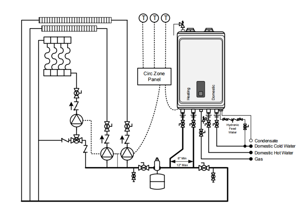
Here's an updated drawing of my own system:
"You have added a loop that is not necessary nor does it have any means of circulating. "
- are you referring to the downstairs loop for the purposes of mixing? The goal is to siphon off return water to cool down the supply water going to the slab. I've adjusted the drawing to better reflect what i'm trying to do. Does that part look more accurate now? Or is there a different way you would suggest mixing the slab supply?
"Yes, you need to add some isolation and purge valves somewhere."
- how about a webstone combo valve (isolation + purge) above the check valves that are above each pump? included in new drawing.
- Drawing currently shows a shut off near a purge on both supply and return, right near the boiler (these come with the pre-assembled primary manifold from Navien). Plus shut off/purge valves above each pump. Do I need more valves? What would you suggest?
Thank you again for the help!0 -
Both heating zones are radiant. If there is no high temp emitters I see no need for a mixing valve with that boiler.
The navien schematics you posted have high temp emitters, and radiant. That's why it shows a mixing valve.0 -
It makes more sense with the mixing valve drawn in and check valves shown.Contact John "JohnNY" Cataneo, NYC Master Plumber, Lic 1784
Consulting & Troubleshooting
Heating in NYC or NJ.
Classes0 -
I now see the mixing valve, it was actually correct in the first drawing. In the second drawing, there is no way for the water to return to the boiler.
I agree with Gordy that it may not be needed. Is there a significant difference in design temps between the 2 zones?If you do install one be sure it has a high enough CV value to match your design flow rate (CV value should be close to the design flow rate) Many models designed for DHW have no place in a heating system due to their restrictive design.
As for purging, you need to be able to push the air out of the system from the fill valve in the direction of flow. A ball valve on the short vertical pipe on the right side of the drawing would prevent reverse flow during purging. A boiler drain in the bottom right corner would be a good place for air and aerated water to be pushed out."If you can't explain it simply, you don't understand it well enough"
Albert Einstein-1 -
Have you performed a heat loss of the two zones? One is staple up, and the other in slab. What water temps does the staple up require, and what does the in slab require?
Depending on the btu requirement for the staple up it is possible you might not need the mixing valve if you can find a happy medium for a awt for the two zones.-1 -
"In the second drawing, there is no way for the water to return to the boiler "
- oops, that was just a mistake. I forgot to add the connecting vertical pipe to the main return (like i had it in the first drawing). I think it sounds like the flow design looks good.
I appreciate all the perspective on the mixing valve. I get a lot of conflicting advice on whether or not it's necessary. I don't think it will hurt anything to add it. I want to be very cautious about not overheating my flooring, and the slab is going to deliver more heat to the flooring than the staple up. I feel like it's a "might as well".
The Taco mixing valve I ordered has CV of 2.3.
@Zman I can add a drain to the bottom right corner with a ball valve above it, but those seem awfully close to the ball valves and drains that are shown just below the boiler. Sounds like you think the bottom right corner would just work better?
Thanks again for all the advice!0 -
Are you planning on having an automatic fill valve at the expansion tank? If so,an isolation valve between the expansion tank and the boiler drains would allow you to purge through the boiler drains."If you can't explain it simply, you don't understand it well enough"
Albert Einstein-1 -
When you say staple up, do you mean plateless staple up? The design temp between plateless and your slab will probably require a mixing valve.
Are you planning on setting up outdoor reset?
One issue with thermostatic mixing valves with your application is that they will not follow a reset curve, they just always maintain the same temp.
I would run a system like that with either a taco I-series smart valve to give the slab floor it's own curve or use a non thermostatic valve so that the slab temps are automatically a set temp lower than staple up curve.
"If you can't explain it simply, you don't understand it well enough"
Albert Einstein 1
1 -
The staple up does have plates covering the majority of the tubing (not really on the loops as that was difficult to wrestle the pre-formed plates around). Was not planning on outdoor reset. I guess I'm being a little paranoid about the temperature difference between the two zones. We do have good spray foam insulation and insulation in the slab. I think you guys are wearing me down and I'm leaning now toward just forgetting about the mixing valve
 Also, I realized that the majority of the "you need a mixing valve" advice came from people who wanted to sell me a mixing valve!
Going to get rid of the mixing sub-loop and just have two simple zones. And I will add a drain with a ball valve above it (or a Webstone combo valve) in the bottom right corner and then it sounds like I should be set!
Thank you all so much for your help!0 -
The mixing valve comes into play "IF" the staple up is going to need considerably higher swt than the slab. Typically they do. However that depends on the load of the staple up.0
-
Initially early on I missed the two different radiant assemblies.0
-
I think you could run without the mixing valve. I assume that boiler is capable of outdoor reset. I would absolutely take the time to run the outdoor sensor and set it up.
Outdoor reset is the key to a comfortable and efficient in floor system. Correctly setup it virtually eliminates overshooting on warmer days."If you can't explain it simply, you don't understand it well enough"
Albert Einstein-1 -
How about a recommendation on the size of expansion tank I need? There's about 750 linear feet of 1/2" pex tubing in each zone (about 1500 linear feet total), and the water heater is the Navien NCB 150 E.
I've heard anything from a 2 gallon tank to a 10 gallon tank.0 -
There are a few factors that go into it. System volume, design pressure and temp range are the big ones. From what you have posted, your 1,500 ft of 1/2" tubing holds 14.1 gallons, the rest of the system will need to be accounted for as well. There is pretty good chance that 2 gallon tank would do the job. A 4.4 Gal would be more than enough and they don't cost much more.
Most manufacturers have sizing calculators on their websites"If you can't explain it simply, you don't understand it well enough"
Albert Einstein-1 -
Thank you Zman. I did end up going with the 4.4 just to be safe, but I was really thrown off by one of the radiant heating supply site's calculator telling me i needed upwards of 8 gallons. I guess that was just plain wrong 0
-
New, unforseen issue...
I'm in a frustrating chicken and egg situation with trying to test my radiant. I cannot get gas connected without a C.O. I cannot get a C.O. without completing my radiant set up (and then installing my floors).
We are able to get temporary electrical power to the panel in the boiler room. My thought was to use a temporary electric tank water heater to run the system.
However, an electric tank heater doesn't have an internal pump to pull the return water back. Everything is already on the wall, we only have the two zome pumps (Grundfos 15-55 Alphas) and very limited time.
Does anyone see a way out of this pickle? What would happen if we tried to run the system with only the zone pumps? Would they burn out trying to push water back to the boiler? There is a very small amount of piping outside the zones themselves (pic attached). Or is connecting the gas our only way forward? (Other than ripping up what we've done, buying a 3rd pump, installing it, and then removing it later which sounds like a nightmare).
Really stuck here, thank you all so so much for the help!!0 -
Can the boiler be easily converted to propane? You could run it off 100# bottles until the gas company connects you.
I my area the gas company only requires one working appliance and an inspected gas piping system to connect."If you can't explain it simply, you don't understand it well enough"
Albert Einstein-1 -
Propane is a great idea at least just to get it tested. Can't believe i didn't think of that!0
-
Assuming your installing 2 radiant manifolds, w/o actuators, you can adjust flow rates to each loop with the tool provided. I install a bypass around the mixing valves to power purge each loop. Install thermometers on the supply and return of each zone so you can regulate temp.
Never used the Ecobee stats but they should have a radiant anticipator.
I typically use Tekmar stats with the slab sensor. They're 24v powered so you need 3 con wire. Not a fan of WiFi stats on radiant. Set it and forget it.
Good luck.0


Categories
- All Categories
- 87.7K THE MAIN WALL
- 3.3K A-C, Heat Pumps & Refrigeration
- 59 Biomass
- 430 Carbon Monoxide Awareness
- 127 Chimneys & Flues
- 2.2K Domestic Hot Water
- 5.9K Gas Heating
- 121 Geothermal
- 170 Indoor-Air Quality
- 3.8K Oil Heating
- 79 Pipe Deterioration
- 1K Plumbing
- 6.6K Radiant Heating
- 396 Solar
- 16K Strictly Steam
- 3.5K Thermostats and Controls
- 56 Water Quality
- 51 Industry Classes
- 51 Job Opportunities
- 17 Recall Announcements