Welcome! Here are the website rules, as well as some tips for using this forum.
Need to contact us? Visit https://heatinghelp.com/contact-us/.
Click here to Find a Contractor in your area.
If our community has helped you, please consider making a contribution to support this website. Thanks!
Moving from series loop finned baseboard to parallel cast iron - how to pipe?
Options
Comments
-
@neilc Sorry I did not explain that correctly. Reverse acting mode says that increasing the pump speed will decrease the deltaT which is the same as wanting the pump to speed up as DT increases. They don't make this easy to remember. In any case reverse acting is defined in the VDT lit and examples as the "Delta T" mode. I corrected my wording in the previous post.0
-
@weekendguy
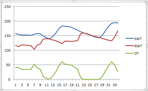
Something is seriously wrong with that data. Look at 10:45 only, on all 3 charts and explain how those 3 conditions can exist.0 -
@paul48 Due to a limitation in my tracking software, DT will not record a value below 0. If it would, we would be seeing negative DT.0
-
You have a crashing supply and peaking return. Was the boiler off?0
-
@paul48 Yes. I was changing boiler settings off and on up until the boiler kicked on at 10:45. It's what followed that I was referring to in my post.0
-
Open some windows, leave the hi-limit alone and re-run that test. If you get the same sawtooth graph, your sampling rate or response rate is no good. It should be close to a flat line at your set DT.0
-
To use the VDT in deltaT operation mode DIP switch 3 remains "ON". Setting it "OFF" will put the pump into Direct Acting mode which does not control both sides of a setpoint - it seeks a setpoint and then shuts down. We know the pump is in the correct mode - it accelerates when the DT increases, which speeds up the flow returning more btus to the boiler. It likewise decreases its speed when DT drops below the setpoint. With help from @Hatterasguy I have identified these issues:
1. Zones are very long and the pump logic cannot as easily manage a closed feedback loop with the longer return delay.
2. Boiler is oversized which causes a rapid rise in SWT putting more demand on the adjusment algorithm (made more difficult by #1).
3. The pump's logic is questionable in that it does not regulate as expected. It allows the DT to reach 12-15 degF above the setpoint before speeding up, and the speedup profile seems compressed. Same thing occurs when the DT is dropping. This behavior has been confirmed with a second control board.
4. The feet of head of the longest zones seems to exceed the specs of the pump (014) although it appears to work. It is possible that the flow rate is very low which will even further delay pump control. I will substitute a 011 pump sometime soon -- according to its specs it should handle a higher head pressure.
#1 and #2 are currently fixed conditions. I have written a detailed email to Taco with data asking for an explanation of the algorithm logic (#3) and for suggestions as to using the pump successfully.
Over 30 years in engineering has given me the interest to work on my home systems but has not exposed me to hydronic systems in particular. I really appreciate the help from this forum and I look forward to finetuning system performance in advance of a new boiler.
Comments welcome as always!0 -
I don't know whether the "00" series DT circs use the same logic, but if I remember correctly, the Bumblebee went to high speed on start up and stayed there for a while to stabilize supply and return temperatures.0
-
@Paul48 That is true of the VDT as well. In DT mode only it goes to full speed for 30 secs to give both sensors a chance to get a starting point.0
-
Re: #1.....Move the sensors?0
-
@Paul48 Thanks for your comment but I'm not sure what you mean. The only place to read S and R temps from all zones is at the boiler.0
-
That's why that response was tentative, and formed as a question. It's the solution to that, but only if workable. You need some more answers from Taco. Think about it........the reasons you are describing for it not working well, are the things it was supposedly designed to prevent, in part. The btus piling up at the boiler because of an over-sized boiler doesn't cut it. That translates into a wide DT, and an accelerating circ.
 1
1 -
@Hatterasguy @paul48 You have no idea how many times I have checked the dip switches and the sensor wiring. Unless they are mislabeled they are correct.
Plus - I've had quite a few calls with Taco Tech Svcs and generally found that the guy on the other end does not know this product. Documentation is confusing. Can one of you guys tell me how this VS pump is different in principle? It has the same DeltaT application pictures as the VDT.
https://www.taco-hvac.com/uploads/FileLibrary/00-VS(PA05).pdf
This has great descriptions of 2 settings that are missing in the VDT docs.
It still baffles me why the pump acts the way it does and I hope Taco can explain it on Monday...
Thank you both for your advice.0 -
@Joe Mattiello
If Joe will respond, you will get the answers you need.0 -
Maybe down load the manual for a Grundfos MixiMiser. I think the use the exact same control, built by the OEM division of tekmarBob "hot rod" Rohr
trainer for Caleffi NA
Living the hydronic dream0 -
@Hatterasguy @Paul48 I have a failure mode theory. What if the pump (which we already know is underspec'ed) can't move any water at lower speeds? So the DT comes down, the pump comes down in speed. Water stops moving. DT keeps coming down. It sits there until the supply pipe cools off, the DT rises and the pump comes up to a speed that can move water again. Look at the graph beginning around 13 where I turned on a single zone. Look at that long (8 min) flat bottomed DT where no change was happening in the SWT and RWT. Reasonable theory?
0 -
Bear with me, here.............I have seen odd behavior with ground issues and electronics.0
-
Refer back to Taco's- Circulator Sizing on FloPro University.0
-
@Hatterasguy What would be a good alternative that could handle the head loss?0
-
Hatterasguy said:
It would be really tough to split the 2nd floor zone - getting pipe from the midpoint to the basement would require opening up ceiling in a few places. The 2218 doesn't look like it can handle 28ft. Is there a larger version?weekendguy said:Given that I am splitting the largest zone, I measured the 2nd largest zone (2nd floor) and found that it's almost identical in length when you add in the risers and the horizontal runners = about 250 ft. Head is 250*1.2*.04*2.31=28 feet. It's pretty clear that the 2218 does not have the capacity for this size loop. In fact this is beyond the range of the 014 (23 ft) so why it works at all is a mystery.
0 -
I believe you're making a mistake calculating head. That's why I suggested you go to FloPro U.0
-
@Hatterasguy I've not run into the idea of two circs in series. Even with the 014 pushing full speed will the 2218 be able to reduce speed as needed?
Also, I'm inclined to split the 1st floor zone just for comfort. The far end is harder to warm up. With 2 parallel circuits I think it could have a positive effect on that problem. Sensible?
Thanks.0 -
@Hatterasguy I am perfectly fine putting $800 into a 3452 circ as well. I just don't have any experience with how to use DP. Would that work for my setup?0
-
@Paul48 I will check out FloPro U. I am certain of the actual length and the pipe diameter. The EL has been estimated with the help of @Hatterasguy.0
-
@hatterasguy @Paul48 I am now unclear on the head calculation.
Using the steps on the taco site I get this:
GPM = 6.5 (65,000 bth/10,000)
H(l) = k x c x L x f^1.75.
For 3/4 copper k = .00295.
at 140F c = 1.0
EL is 315.
f^1.75 = 26
.00295 x 1.0 x 315 x 26 = 24 feet. This is too high for the 2218 and is right on the ragged edge of the 014. Given that the 014 works somewhat helps validate the EL. The 011 is much better and will provide 6gpm at 27 ft. The 014 might only be doing 3 or 4 gpm which could easily screw up the DT algorithm.
I think before doing anything I will put the 011 in. My wife will kill me if I attempt this tomorrow but I will get to it in the next few days.
Thank you both for making me look at this again (and again). I feel optimistic that this will be much better.
Maybe we can get this resolved and get back to the business of selecting a boiler...0 -
@Hatterasguy I will report back after the 011 is in and operational. On design day test does the 50% duty cycle refer to
--recovery of usual zones or all zones, or
--maintaining temp in usual zones or all zones?
0 -
@Hatterasguy Thank you. It sounds like on a design cold morning I turn on all zones with 160F SWT and watch to see if they all satisfy after some time period. How long do I wait before I conclude "no"?0
-
The flow requirements and those loop lengths are killing you. The difference in head loss between 6.5 gpm and 4 is huge.0
-
@paul48 The 2nd floor zone is situated at the far end of the house - away from the boiler. So part of the 250' loop length is just getting there horizontally - probably 100'. I'm thinking maybe I can replace that section with 1" pex to reduce the head loss. The emitter loop and the risers would still be 3/4" but at least I can improve 40% of the length. I haven't calculated it yet but I think that would be a measurable change in head loss. It's not an easy job but it's doable without opening up walls and ceilings.0
-
It's about flow requirement, more than length.
http://www.sta-rite.com/resources/images/14800.pdf0 -
That's why Taco's quick and dirty calc won't work for you. Look at the 4 gpm, which is where you should be, and the head is reasonable.0
-
@paul48 It would be great is 4gpm would work but at 4gpm it won't meet the BTU need of this oversized zone. It's a 65,000 btuh zone based on the emitters (and heat loss). I used the 10,000 btuh per gpm constant to get to 6.5gpm.
Looking at the loss per coupling on that chart makes me want to bring the EL down somewhat since we have very long runs. I think a mutiplier of 1.1 should be adequate. So the EL becomes 277. At 6gpm on your table that's 9.22 X 277 = 25.5.
I think the current pump is probably running at 4gpm at its slower speeds and looking at the pump curves it can't possibly have more than about 20 ft of loss since the zones actually work with the current circ.
I just thought of this. The original installed circ was an 010 which has a max head of 10. How did this work for 10 years? Other than the boiler short cycled alot. I think maybe that information was what Taco used to size the 014.
I'm confused. I wish I could measure the actual flow. I suppose I could let the zone cool down and time how long it takes for the far end to see a rise in temp and then convert pipe volume to gallons.
The longest loop holds about 7 gallons. If it takes 2 min for the end of the zone to see the hotter water that's 3.5 gpm.
I'll try this and see what I get. Now I'm not sure I need to put the 011 in place. Thanks for your help.
0 -
If it were mine, I'd split that loop and any other to keep the load at 40k or under. If it's just drywall repair, that's not a big deal. You could have most of the job prepped before you even shut the heat off. I know..........but the fun never ends, 'til they throw the dirt on ya.0
-
@paul48 The problem is the zone is so far away that splitting it would not shorten the loop length much. The only way I can think to do it would be to run a larger supply to that end of the house and tap 2 sub-loops off that. If I get the right gpm from the current setup I think I'll try to live with it as is. On that note, I ran 2 tests on the circ at full speed on a cold zone. I timed the return water and got 1:11 and 1:15. So that's about 6.6 gpm in my highest head zone. This validates the 014. My next test is to run it on low speed and do the same thing.0
-
Forget the loop length. Calculate your 6.5 gpm requirement split to 2 circuits at 3.25 gpm and see what you get for needed head.0
-
@Hatterasguy I've gone around in some circles today but I think I made some progress. I understand your advice to not split the zones but rather work on getting the pumping correct. I re-timed my longest zone once I realized that I had not synchronized the end switch with the pump starting. Here is what I concluded: It took 150 secs for the 7 gal of hot water to make it all the way around the loop on high speed. That comes out to 3gpm. On high. So this circ may do a half-**** job of heating the house but it won't work as DT circ (as we have seen) because at half speed it probably can't move anything at all. But now that I know the GPM on high, I can go back to the pump curve for the 0014 and I see that the head must be around 21 or so. If I need 6-7 gpm at 21 head then the 0014 is too small (can't move water unless on high). The 0011 I have is too big because on high it moves 12 gpm so on low it will move 6 gpm. I need a pump that will move 6 on high and 3 on low. Looking at the pump curves it seems like the 009 is the winner. At 21 feet of head it moves 6gpm. Perfect. But before I shell out $400 to add to my growing collection of VDT pumps, I would like to know if my logic hangs together. Comments? Thanks again.
http://www.taco-hvac.com/uploads/FileLibrary/101-133.pdf
0 -
@Hatterasguy That's why I was hoping you could comment! Thanks for catching my bad assumption. I see what you mean about coming in at about 7gpm. I'll drop the 011 in soon and let you know (assuming I can get the air purged) :-) Many thanks.0
-
@Hatterasguy Oh boy, I am red-faced on this one. I went to get the 0011 out of the box marked 0011 and it's.... an 0014. Which means (and I confirmed this) the one on the boiler IS the 0011. So I guess I'm in the market for something even bigger. Going back to the pump curves I can see that the 3gpm on high on the 0011 corresponds to a head loss of not 21, but 29, which I think is where you calculated it a few days ago. So I need 6-7gpm @ 29 feet. The 0013 shows 8 gpm at 29 feet. Going back to the longer EL of 315 feet and looking at the table for 6gpm, the head loss is exactly 29 feet. So I think the 0013 can provide 6gpm (maybe slightly more) at 29 feet which should do the trick. Sorry I went down the wrong road with the wrong pump but at least you stopped me from buying an 009... :-)
If this sounds reasonable, I'm going to take advantage of the 5% Trade Tuesday discount at supplyhouse.com tomorrow and get one.
Thanks again. I'm looking forward to getting this finally pumping correctly even if I need to shell out a few hundred more dollars. It will be worth it to know all is well before I invest in a new boiler.
0 -
@Hatterasguy
The pump is clearly marked as an 0011. I set up 2 resistors that let the pump think it had a DT of 80-100 and repeated my timing test. The time was the same = ~150 seconds. The pump starts on high for 30 sec by design. I can tell both from the indicator and the motor pitch that it never drops in speed.Hatterasguy said:
The question begs why the 0011 isn't delivering the flow rate. Either it's not actually an 0011 or the EL is actually considerably more than 315, or the pump does deliver the flow rate at certain points in the operation but then slows for unknown reasons and allows the DT to climb excessively.
If I vary the length of the loop by 30ft (10%) in the calculations I still get between 3 and 3.6 gpm. This is using the actual ID of type M copper so I'm very sure of this.
So the EL must be considerably more than 315.
On high it only moves about 50% of the water. So on low it's either not moving hardly at all, or it's moving about the same amount - either way it can't cause a meaningful delta in flow so we can't expect the pump to manage a delta T. This of course assumes the correctly sized pump will change speeds at the correct DT which is not what we have seen. Still waiting for Taco to respond to my email on that one.
I have a friend who is an installer who pulled out a few of these VDT pumps last year and has some in his shop. If he has a 0013 he will let me try it. Even a non VDT 0013 will let us confirm the flow rate. I'll call him.
Before I go to the trouble of doing the swap I will call Taco and share this information for their comments.
Thanks again.
0 -
@Hatterasguy I had a chat with Taco tech services who did not fully understand the situation I described but did confirm that the 013 should achieve the needed gpm at full speed. My friend the installer knows somebody who has various VDT pumps in his stock and will loan me one to check it out. Assuming he has a 013 I should have it later this week and will drop it in over the weekend.
Also - it occurred to me that I can downfire the current boiler to simulate a new smaller unit by replacing the propane orifice. Right now the DOE is 175. I can drop one size to get to 145 or 2 sizes to get to 115. This would allow a temporary checking out of the lower level of output. This seems to be worthwhile. What do you think? Thank you.0


Categories
- All Categories
- 87.7K THE MAIN WALL
- 3.3K A-C, Heat Pumps & Refrigeration
- 59 Biomass
- 430 Carbon Monoxide Awareness
- 127 Chimneys & Flues
- 2.2K Domestic Hot Water
- 5.9K Gas Heating
- 121 Geothermal
- 170 Indoor-Air Quality
- 3.8K Oil Heating
- 79 Pipe Deterioration
- 1K Plumbing
- 6.6K Radiant Heating
- 396 Solar
- 16K Strictly Steam
- 3.5K Thermostats and Controls
- 56 Water Quality
- 51 Industry Classes
- 51 Job Opportunities
- 17 Recall Announcements