Moving from series loop finned baseboard to parallel cast iron - how to pipe?

I should mention there are 6 zones all together and a few years ago I replaced the existing Taco 010 with a Taco Delta-T Variable (I think it's a (014). This helped even out the heating at 20* DT so I'm inclined to keep this in place if it seems rational to do so.
I learned alot from Dan's books (and this site) and my system is much improved as a result. But if there is a Mod/Con in my future, I think the additional mass of the cast iron will be a real advantage. I've never had a parallel configuration - only series loop. A few questions for you wizards:
Anything wrong with this approach in general?
Any negative effect of having different size parallel legs? - There will be 3ft and 8ft sections next to each other.
Will the flow balance out or will I have flow issues at the far end? Any reason to step pipe sizes up/down to compensate?
Do I need to use monoflow valves or something else like that where each section is dropped off the main lines?
Comments
-
@Hatterasguy - This is sage advice, and thank you for addressing my questions in that order. I was implying that I WOULD have a mod-con since I am expecting to replace the boiler in a year or so. My Weil is now 20 and has run half its life on oil and half with a Carlin EZ-GAS LP burner. I've probably stressed its temperature tolerance with the outdoor reset I added. But now that you point out the investment return, it's hard to justify a mod-con if it means spending something north of 25K just for the new radiation system and another 10K+ for the boiler. I suppose I can live with the finned baseboard with just a boiler replacement. I noted the Burnham ESC will accept 110 degree return water which gives me some wiggle room when my ODR gets ambitious and cranks down the target temp. And a boiler in that class has got to be more efficient than my current "franken-boiler".
0 -
@Hatterasguy - Thank you for confirming my thoughts. Having beat up this Weil with "too low" return temps and aggressive ground water from our well I keep thinking that any day it's going to croak. I'm not planning to pull the trigger on the Burnham immediately but I want to have plans in place so I'm not under even worse pressure when it starts to leak Christmas week. :-)
Re: sizing - I'm doubtful that the ESC3 or 4 will be sufficient. I have all the heat gain/loss information in a spreadsheet from back when the house was built. You are correct that they oversized it (even after I cautioned them to trust the numbers) but apparently only by one size - when I converted it to LPG I spec'ed the Carlin burner at one size smaller - from DOE Heating Cap 213 mbh down to 175 mbh. That corresponds to 203 mbh input. When 5 or more zones are active I would not want to be any smaller on a 20 deg day. I forgot to mention the 60 gallon indirect DHW zone, as well. Having looked at my venting options I think I'll need to continue to use the atmospheric venting so the Burnham ES2 is the likely unit. ES27 has 210 mbh input so that's what I'm using as a placeholder until I get someone qualified out to quote. Lots of heat pump guys around here (SE PA) but not as many good boiler guys. It may take a few tries to find someone I'm comfortable with. That's my next challenge - suggestions welcome!
0 -
@Hatterasguy - Thanks again for sharing your knowledge and experience. It's a 20 year old house with 4 finished floors - well insulated and tight. Total sq feet of all conditioned space = ~7400. Primarily use 3 zones - 1st floor, and (2) 2nd floor zones = ~4900 sq ft. The other areas stay closed off and pretty cool unless we are using the space. I checked the heat loss spreadsheet - the 3 primary zones total 130,000 btuh (without the DHW). The other 3 zones add another 42,000. At times we have 6 people living here during which DHW needs go up significantly. On a cold morning when we're coming up from night setback the boiler will run something like 30 minutes on. A smaller boiler would run longer I suppose - how long is too long?0
-
@Hatterasguy - This is so helpful - thanks for the run time info - I have always wondered about optimal run times but I never found it specified anywhere!
I built a boiler auxiliary controller that (among other things) records DHW and boiler temperatures to the cloud every minute. If I look at the sawtooth 'Supply" pattern I definitely see periods shorter than 10 minutes. If you're interested...
https://thingspeak.com/channels/110973
Look at the "Supply" graph. You can hover over the lows and highs and see the boiler on and off times.
It's 40 degrees right now. The live data on the graph shows typical cycles at 4 and 5 minutes. I will kick on the other zones tomorrow at 6AM and see what the recovery run cycles look like but this current situation is pretty typical. I might be able to tweak the H'well tstats to increase the hysteresis which should lengthen the cycles but that will cause a greater temp swing in the zones so not ideal.
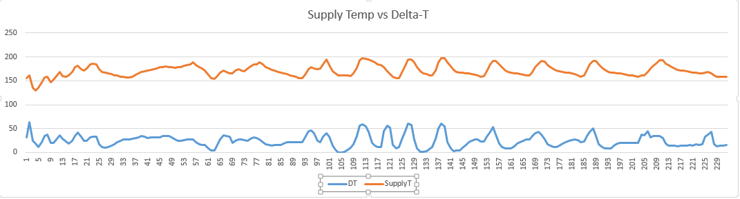
If you look at the graph, what do you think about the supply temperature range for fin tubing at 40 deg outdoor temp? It looks like lows around 150 and highs around 185. I keep fiddling with the ODR values. It's sad being a boiler nerd. :-)
0 -
Hatterasguy said:
I don't follow this - can you elaborate a bit? And yes, I will turn on the other zones in the morning to see how the full recovery from setback goes. That data will populate the supply graph in real-time.weekendguy said:
You also have the benefit of running a relatively high SWT of 165F, which you don't need at these temps. When you lower that temperature on the ES, the cycles get even shorter, of course, because the radiation cannot deliver the BTU's at lower water temperatures (but the boiler output is fixed).0 -
This is exactly why I keep fiddling with the ODR. I try to avoid temps being too high but when they get too low I can stand by it and see the deltaT drop to 3 because the convection is so poor. Is there a sweet spot?0
-
@Hatterasguy - Thanks again.
>>1) A boiler that is very closely matched to the heatloss.
--- if we can identify this accurately then the new boiler can certainly be sized accordingly.
>>2) Radiation that allows 160F SWT on the design day (which you may currently have).
--- Do you mean sufficient radiation to meet BTUH demand @ 160degF? If so, I doubt that is in place. I'm pretty sure the calculations were done at 180 degF.
>>3) Use of the Taco VT2218 to keep the DT higher even with lower SWT.
--- Not that exact model, but currently using Delta-T Variable Speed Taco 0014-VDTF1 which made a huge difference in leveling the distribution of heat. This is one reason I built the aux controller so I could track what the circ "thought" the D-T really was.
So I will inform you of the recovery cycle information tomorrow AM. Thank you again. It's nice to talk to someone who understands where my questions are coming from and why they may be significant (at least to me).
0 -
If you look at the cloud data you can see the D-T for the last few hours. If you compare it to the supply graph, you can see that the lowest D-T levels correlate to the lowest supply temps. I am assuming that is because at the low temps radiation is nil hence most of the btus are coming back. It may be hard to truly assess this in the shoulder season...
The 0014 was suggested by Taco given my ft of head estimate.
I just spoke to the Product Manager at Taco. The 0014 will drop down to 40% of stated flow rate when it's at its slow speed. Based on my experience getting the D-T where I wanted it he did not think it was oversized.
BUT - I'll recheck the size of the loop and see how that lines up on the performance curve and let you know. Many thanks.
0 -
I didn't follow your last post - could you elaborate a bit?
Here is what I found. The longest loop (1st floor - most commonly used zone) is 270 ft long requiring 69,000 btuh. I know this is too long for 3/4" pipe -- I am planning to split the zone near the middle. I used ft*1.5*.04 to get FOH = 16. Looking at the taco performance curve for the 0014 that's about 10 GPM at full speed, ranging down to 4 GPM on slowest speed. When I added the VDT pump the zone came up to temp much faster. I attributed this to faster pumping therefore not letting supply temp drop half way through the zone starving the far end of the zone. In other words D-T had been too great, the faster pump brought it down. Please correct my assumptions if they are incorrect. Thanks again,0 -
This morning I turned on 5 zones at the same time (38 degF OT). The boiler did this: on 30, off 10, on 5, off 10, on 8, off 6. These cycles are too short by your 10 min rule suggesting an oversized boiler. But how do I extrapolate these times for an OT of 15 degF? I will extract the actual temp data and post some more detailed graphs later today when I get to my office.
I measured the piping instead of using the floor plans and I came up wih 252 ft. There are lots of long runs considering the room sizes so the 1.5 is probably high. So 252*1.3*.04*2.31=29. That still seems high for the circ I agree. But I was able to change the DT setting on the circ and the results changed as expected so for whatever reason it seems to be in a manageable range. Pipe is 3/4", circ is 0014.
I think it's a different problem to solve when only one zone is open versus many since the circ is only seeing average temps - speeding up to lower average DT will impact the short zones differently than the long zones I think, especially when the GPM is divided between multiple zones.
Thanks again.0 -
@Hatterasguy - Thanks as always. Graph of boiler behavior starting 5:00AM follows. Each count on the horizontal axis is a minute. You can see the one long run cycle when all the cold zones opened at once and then shorter ones began.
Link to image: https://us.v-cdn.net/5021738/uploads/editor/x4/4q4hs60xr8xs.png
The DT during recovery period averages 25 with a STDEV of 18 which I agree is pretty wide. I'll call the Product Manager back today and see what he thinks about the sizing and the expected hysteresis.
FWIW - the house had only come up to 66 degF from 64 degF after 1.5 hours. So I guess this is the tradeoff you mentioned - tolerate longer recovery with a smaller boiler or expect short cycling/inefficiency with a larger one...
It would be useful to extrapolate these readings to a lower outdoor T. Heating the house at 38 degF has never been a challenge but before the VDT circ it could take 4 hours to come up on a cold day.
0 -
So the boiler ran about 30 min with the additional load which satisfies the 15-20 minutes you mention here. Do you believe I can go forward with the ES2-7? Waiting for a call back from Taco Prod Mgr. Also, see screenshot from the online order for the circ. Thank you for your continued help and advice.Hatterasguy said:I believe you are not running the extra 42,000 BTU and we would not want to make any decisions without that load. Can you run the test again with that additional load? Would like to see if the boiler can run for 15-20 minutes before reaching HL. If it can, you're close on the sizing and the ES-27 will probably be correct (especially if you demand to have reasonable recovery time close to the design temperature).

0 -
I can repeat the test in the next day or so as you have suggested. As I mentioned, the 69K zone is too long and I plan to split that into either 2 separately controlled zones or 1 controlled zone with 2 separate loops. IIRC the 69K was at 180 degF so with the ODR working and 40 deg ODT I agree that 69K is not being delivered due to the lower SWT.
I have the heat loss data from the original analysis which shows the calculated feet of bb. It may be slightly different than what was installed but the net should be pretty close. It shows 124 feet of bb for the large 1st floor zone. If needed I can always do a direct measurement. FWIW the (2) 2nd fl zones total 110 ft. All zones together total 310 ft. This makes general sense I think - at 180 degF the emitters are 580 btuh/ft. = 180,000 btuh which is within a few percent of the system heating capacity.
Many thanks!0 -
The Taco Viridian circs look really nice. I would consider replacing zone valves with indivdual VS circs if they can be sized with my setup. That should help match things up better.0
-
I have ball valves installed on each zone so can tweak that. Yes I have IR gun and will check RWT on that zone. I will report back!0
-
Nothing gets my day off to a great start like an hour with my boiler in my pajamas. :-) I have a Honeywell AQ251 control on my boiler so I set the high to 190 and the low to 160 (too low?) and left the diff on auto. I turned the ODR off. 28 degF ODT.
Opened all zones and set stats for at least 4 degrees of recovery. Then I started looking at individual return temps with my IR gun and tweaking the ball valves. I got them all returning water within a 5 degree range. It's amazing how much resistance that long zone has. It was wide open and the other 5 were almost closed (see pics).
https://goo.gl/photos/Ee1rMzUj8mVhdYnD7
These ball valves are pretty coarse - it's hard to get them dialed in but I got them pretty close. I imagine adding some of those multi-turn valves with the screwdriver slot when we put in the new boiler. I don't know what they are called but they are more precise than the coarse ball valves which are intended to be open or closed.
Within 1 hour 2 zones were satisfied and by 2 hours everything was satisfied. The first run of the boiler was about 35 min, then it settled into 5 on, 7 off - let's say approx 40% duty cycle. I agree now that this is too big considering the capacity of the emitters. I'm learning as we go here. The next size down ES26 is 20% smaller which suggests that the cycle run time would need to be 20% higher (6 on, 7 off) which would not affect the duty cycle in any meaningful way. This assumes a linear relationship which I have not thought through fully and may be wrong. Of course this was at ODT of 28 degF. Design is 14 degF. Can this be extrapolated? Sorry I am rambling - still trying to pick a boiler size.
When looking at unit sizes, would the 160,700 be compared to the DOE Heating Cap or the AHRI Rating?Hatterasguy said:310 feet will deliver 160,700 BTUH @ 180 SWT. Therefore, any boiler with a net output larger than 160,700 should never be installed. It remains to be determined if you actually need 180F to maintain temperature in the building at your design day.
DT was fairly steady for the longest run time averaging around 25 degF. I can probably tweak the Taco to get that down somewhat. I'll pull out the data and post it later.
I have to wonder if the ODR is doing me any good considering the inefficiency of finned bb at low temps. I am considering changing the ODR settings so the boiler stays between 170 and 180 degF for high and set the diff to 20. How do you think this would this work? I'm not in love with the ODR and if I can downsize the boiler and pick up some efficiency I'm fine with that.
I understand that the 3/4" piping is something of a limitation in that it can't deliver more than a certain number of btus on a long zone. I still think that splitting the 1st floor zone would help with that issue as the DT over half the zone would certainly be less than the current DT over the whole zone therefore 2 split zones would deliver more heat. Is this thinking on track?
Will post the graphs. Many, many thanks. I'm feeling like I'm making progress.
0 -
For the extra long zone, if you could run a 1 inch supply to the mid-point of the zone, and then tie the other ends of the "split loop" zone to the return piping, that would really help even things out with your shorter zones and reduce the required pumping energy.
Baseboard doesn't put out a lot of heat at low water temps, but if you have enough if it, it can do the job quite well. My house has a low temp baseboard system, and it heats the house really well. This morning with an ODT of 28F, the system was running with a supply temp of 106F (two of three zones calling). A thorough heat loss analysis and emitter output analysis is the key to a successful low temp system.Hydronics inspired homeowner with self-designed high efficiency low temperature baseboard system and professionally installed mod-con boiler with indirect DHW. My system design thread: http://forum.heatinghelp.com/discussion/154385
System Photo: https://us.v-cdn.net/5021738/uploads/FileUpload/79/451e1f19a1e5b345e0951fbe1ff6ca.jpg0 -
@Brewbeer Thanks for your comments. A common return was what I had in mind except I was planning to use 1.25" orange pex. What kind of Delta-T do you get with 106F baseboard?0
-
@Hatterasguy Here is the graph. DT is relatively stable. You can infer boiler runtimes from the supply graph.
0 -
@weekendguy I get a DT of about 4F at 106 SWT with the two long zones running (47 ft and 48 feet of finned baseboard, respectively) based on the temp sensors on the DT circulator (Viridian 2218 running on lowest setting). Not sure what each zone DT is. My system is unusually piped, each radiator is piped in 3/4 inch copper off a larger 1 inch copper main using a split loop configuration. You can get more info on my system including some fairly detailed calculations of estimated supply and return temps for the radiators in the thread linked in my signature.Hydronics inspired homeowner with self-designed high efficiency low temperature baseboard system and professionally installed mod-con boiler with indirect DHW. My system design thread: http://forum.heatinghelp.com/discussion/154385
System Photo: https://us.v-cdn.net/5021738/uploads/FileUpload/79/451e1f19a1e5b345e0951fbe1ff6ca.jpg0 -
@brewbeer Thanks. I just read your design thread. Sounds like you thought things through quite well. Glad it's working for you. My options are somewhat limited. The system was installed by an air conditioning guy that the builder selected. Longest run is 242 ft of bb. Even with a Taco VDT that zone is tough.0
-
@weekendguy If you are at the point where you are getting ready to change out fin tube baseboards for panel radiators, you may be in a position to change the way water is delivered to them. Others here have piped panel systems using homeruns from each panel to manifolds, which would allow you to better balance the amount of water delivered to each radiator based on it's output. A reverse return set-up might also work for you.
The key piece is getting the heat loss and radiator outputs to accurately model the real life conditions at your house (and then sizing the boiler correctly). If you supply each of the new panel radiators with the same temp water using a home run or reverse return system, that makes the calculations necessary to size the radiators accurately for the heat loss of each room fairly straight forward. However, if you pipe the panel radiators in series, you need to account for the lower water temperatures leaving the first radiator when determining how large the next radiator needs to be based on those resultant lower supply temps. This means that if you pipe panels in series, the first radiator will be comparatively small, with each successive radiator getting larger and larger. There is a limit to how many panels you can run in series.
Also, if you are thinking about a mod con boiler in the future, you will want to size your new panel radiators for low supply temps, probably no higher that 140 degrees on the design day in order to get the boiler operating in the condensing range for most of the heating season. If you intend to keep some of the house set up with baseboard, you need to look at baseboard output at lower temps to make sure there is enough to heat the house using the lower supply temps.
Given the oversized boiler that was initially installed in your house, the original heat loss calculation performed when the house was built is questionable. You would be well advised to re-do the heat loss analysis yourself, taking careful measurements and summing up the heat loss on a room by room basis. Take this number, and compare it to a gas consumption heat loss analysis, and then you will have a realistic evaluation of how accurate the heat loss calculations (both the original and your new estimate) really are.Hydronics inspired homeowner with self-designed high efficiency low temperature baseboard system and professionally installed mod-con boiler with indirect DHW. My system design thread: http://forum.heatinghelp.com/discussion/154385
System Photo: https://us.v-cdn.net/5021738/uploads/FileUpload/79/451e1f19a1e5b345e0951fbe1ff6ca.jpg0 -
@Brewbeer Thank you for your ideas. Actually I had decided to use a parallel with reverse return approach since I already had the return pipe in place and it would be so nice to even out the "rungs" of the ladder. But after talking with Hatterasguy, I realized that I can't justify 40K for CI rads when I have generally working emitters in place that are less than 20 years old. He has been helping me determine where to walk the line between lower SWT and efficient emission. Today I ran my boiler at high temp for recovery and it was a pleasure seeing the house warm up so well. I'm looking at the Burnham ES series and even though it's atmospheric it has a net flue temp of 230F and claims to be at about 85%. My current Franken-boiler is probably at 75% on a good day. I think trying to get to 92% by adding a lot of complexity and expense does not make good sense for me. My kids are in college or beyond and I don't have 30 years to recover a large investment.
I'm very invested in getting the new boiler sized correctly. I would like to re-do the heat loss analysis but it's just an overwhelming process with a house of this size. What software did you use? Maybe I can be convinced to give it a go over the holidays.
I read your design thread and am interested in your process. Clearly you were very careful to work only from a confirmed design (not often somebody refers to DiffEQ on a DIY site :-)) My son is looking at a house with scorched air and A/C and we have been talking about adding a boiler and running pipe. Did you use orange PEX? I'm pretty comfortable with copper (he is not) but PEX is so much faster to run.
How did you get risers to the upper floors? It's that kind of stuff that really takes time.0 -
@weekendguy I used a spreadsheet to perform a room-by-room heat loss calculation for my house. A copy of the spreadsheet is attached to one of the posts in the thread that describes my system. If you want to give this method a try, send me a PM with your email address and I will email you my spreadsheet. I also calculated heat loss using the therms used and degree day method that others have posted on The Wall, and that method came in with a slightly lower heat loss than the spreadsheet method. If you can get good info put into a spread sheet, it will be pretty accurate. The time consuming part is making all the measurements and assigning r-values to the various building assemblages in your home.
I did my entire house in 3/4 and 1 inch copper. In retrospect, I probably should have done the piping in PEX, the copper piping was time consuming and quite expensive. For what I spent on copper pipe and fittings (over 1 K), I probably could have purchased all the PEX and the tools necessary to work with it.
I have a 4 level house (front/back split), so piping the lower two finished levels for the most part wasn't hard, as there was good access from the unfinished basement. The only place where I needed to cut into a finished wall was in a bathroom, and I was able to cut into the tiled wall behind a door to run pipe. I also had spare wall tiles so I was able to repair the holes and grout the cut lines to good effect. The top floor was more challenging, as it is located entirely above a finished level. This required cutting holes in drywall in the basement stairwell, in the bathroom ceiling, and to remove the toilet and cut through the floor of the bathroom above to get the piping where it needed to go (see attached photo). Once the piping was up to the top level, it was just a matter of drilling though adjoining walls and running pipe from one baseboard to the next in the adjoining rooms (after performing sizing calculations for heat carrying capacity of supply water for radiators piped in series).
In retrospect, PEX would have been faster to run, and required fewer and smaller cuts into house finishes. If I do this project again in another house, it will be run in PEX. Hydronics inspired homeowner with self-designed high efficiency low temperature baseboard system and professionally installed mod-con boiler with indirect DHW. My system design thread: http://forum.heatinghelp.com/discussion/154385
System Photo: https://us.v-cdn.net/5021738/uploads/FileUpload/79/451e1f19a1e5b345e0951fbe1ff6ca.jpg0 -
I insulated those pipes some years ago except for a few I could not get to with some good rubatex. I'll make another pass through.Hatterasguy said:
In your situation, you'd definitely want ot insulate any of those 3/4" lines in the basement as you're running relatively hot water through them.
You mention a steady DT of about 25F. What is the pump setting?
I'm fairly sure the pump is set around 20F - I will double check.
I think this must be fairly typical behavior based on the flow dynamics. Here's how I think about it: the boiler kicks on and starts to send an increasingly higher SWT to the zones. Meanwhile there is a delay until that water returns - initially the RW is from the end of the previous cycle and at least 20 degF below the SWT. As the SWT increases the RWT does not increase for some time and the delta grows. Eventually the "new" hot water makes it back and the delta shrinks back down. The pump does not change speeds based on the increased delta for some time (there are a few related settings). So intuitively I don't think it is the case of the pump not keeping up but I am not 100% sure. I will confirm the pump settings and I will run an experiment on a short zone to see if the hysteresis is better damped.Hatterasguy said:
Your graph over time indicates widely varying DT's............from zero to nearly 50 on the boiler cycles. I'm a bit confused about that and whether the pump is actually holding a proper DT or not?
I'll go with this for now and see how January feels. I will need to set a diff so there can be a range. What is the lowest temp you would suggest with 160 at the top?Hatterasguy said:
you may be perfectly setup with a SWT of 160F and nothing more needs to be done until you get the ES.
0 -
Thank you. To come up with the 310 ft of bb I used the table from the original projections. That may be off - I'll do an actual measurement and update that number. Also, the 175K is the output of the next size smaller Weil than the one I have (WGO-6). When I did the Carlin conversion I spec'ed the orifice for the WGO-5. However, that may not be exact. I will check the Carlin literature and dial in the output based on the LP usage.Hatterasguy said:
Since the Weil has a DOE output of 175K, we can state with some certainty that the emitters were utilizing 40% of that value or 70,000 BTUH. Note a serious discrepancy between this value and the calculated value of 160,700 BTUH
Regarding the 160,700 - what about loss at the boiler and transmission loss? I imagine the emitters don't get the full load of BTUs.
0 -
@Hatterasguy - I checked the Carlin info. It matches exactly the WGO-5 specs: 175K DOE and 152K AHRI.0
-
I believe Hat has witnessed that Taco's DT circs respond rapidly to changes in DT. He's spent some time sitting on a bucket in front of a mod/con, trying to get it to play nice with a DT circ pumping direct.0
-
@Hatterasguy Thank you again. The VDT is installed correctly. One reason I built the Aux controller was to watch both sides of the circ to confirm its operation. I will characterize two of the loops - one large and one small to measure the time it takes for the RWT to come within a reasonable DT of the SWT. With an EL of 327 ft the long loop will take longer than is typical obviously and will delay the circ's response. I have two options set - one is "fast response" which uses speed changes to anticipate the temperature movement. The other is "lower speed" which drops the lowest speed from 55% of max to 45% of max. If we are satisfied with the slow operation I can turn than off which should damp the overshoot and cause the circ to reach high speed a bit sooner. I am measuring the actual baseboard and 1st floor is correct although lower level is much less than in the spreadsheet. I'll finish measuring the whole house in the next day or two with a 10 min break for turkey. ;-)0
-
@Hatterasguy
Total actual installed baseboard = 284 feet. Slant Fin 30
@ 150F-----400 btuh/ft -----113,600.
@ 160F-----480 btuh/ft -----136,320.
@ 170F-----540 btuh/ft -----153,360.
@ 180F-----610 btuh/ft -----173,240.
Does this shed any light?
0 -
I wish I could find the pump curve for that circ. Any of the curves I have ever seen for DT circs are different than standard circs. I'd love to know its operating range for DT.0
-
@Hatterasguy @Paul48
I attached a graph of some run data with largest and most commonly used zone calling. I added some notes that indicate maybe the circ is not keeping up although I feel like its speed-up response is really slow - I will check the sensor mountings tomorrow. I also have on my shelf a brand new 0011 VDT which seems to move equal GPM but against higher head. Could this be a better option? Taco VDT literature:
taco-hvac.com/uploads/FileLibrary/101-133.pdf
0 -
@weekendguy
Never mind my ramblings.......I was confusing my memory of a DP circ curve with a DT.0 -
Or another idea is to pick up a 2218 circ and put it in place. I suppose I should complete the zone split first to assess performance. @Hatterasguy Do you think the 2218 will handle he job? It's got a much greater range of HP and seems like it's more advanced in options and algorithms. I will ask the Taco Product Manager his opinion on comparing it to the circs I have.weekendguy said:I also have on my shelf a brand new 0011 VDT which seems to move equal GPM but against higher head. Could this be a better option?
I'm lining up some labor (sons) to help with the zone split project. Normally I would think of using 1" copper to return 2 lines of 3/4" copper. If I switch to pex I have less volume in the 1" pipe but also less friction so it's argued to be equivalent. 1" pex is preferred by me since I'm not confident going any higher. Any advice?
0 -
@Hatterasguy Not only are the sensors insulated, I frequently check them with an ohmmeter (this morning right after the characterization run) and they match the digital sensors that sit right next to them within 0.5 degF. I agree the pump response seems very poor. I will share this info with the taco product mgr for his comments. One thing I could try fairly easily would be to swap in the 0011. Would that be worth a try?0
-
One other thing I should note regarding the pump performance in the above graph is that not only did the pump wait until 32F DT before speeding up, it went from slow to full speed at once. There was no ramping at all. From a controls perspective if the pump is trying to maintain 20 DT it should be speeding up BEFORE 20 F to anticipate and damp the hysteresis, not 12 deg later. Bottom line for me: you are correct @Hatterasguy - the pump is not performing to spec. I may be able to pull the control board off the 0011 and drop it in without breaking the water envelope. I'll see what Taco says next week. Would still like your opinion on the viability of the 0011 in case I need a full swap. Happy Thanksgiving.0
-
@Hatterasguy - I pulled out the manual for the VDT and I have some config notes given to me by Taco although they don't make complete sense so I will investigate. However it does state that the control board can be swapped out so that will be tomorrow's project.0
-
If the control board swap doesn't solve it the 0011 pump is next. If it does solve it Taco owes me a replacement control board! :-)Hatterasguy said:Be nice to see the 011VDT perform..................
0 -
@Hatterasguy - It's on reverse acting mode since this is a delta T operation (speed increases to decrease DT). I swapped out the control boards this morning and not seeing any difference. Right now the DT is set at 15F and I can watch the DT rise up to high 30s before the pump speed increases. This does not make sense although is apparently how the algorithm works. I'll send this info to Taco for comment next week.
Given that I am splitting the largest zone, I measured the 2nd largest zone (2nd floor) and found that it's almost identical in length when you add in the risers and the horizontal runners = about 250 ft. Head is 250*1.2*.04*2.31=28 feet. It's pretty clear that the 2218 does not have the capacity for this size loop. In fact this is beyond the range of the 014 (23 ft) so why it works at all is a mystery. The 011 has a head range up to 32. Do you think the next step is to swap that unit in and see how things work?
Doing so will not correct the poor response. Maybe there is an updated circuit board with new firmware. I'll find out but I may be stuck with this limitation of widely swinging DTs.
The DT seems to be at its worst when the boiler quickly ramps up temp. This is in part due to the oversized boiler and may not be as bad with one that takes longer to increase SWT. You can see in the graphs how the DT is reasonable while the SWT is declining slowly but it can't respond fast enough when the SWT spikes (abt 11:15).
As always, thanks for the advice and education.
0 -
I think you would want the pump to speed up as DT increases,
try direct acting actionknown to beat dead horses0


Categories
- All Categories
- 87.7K THE MAIN WALL
- 3.3K A-C, Heat Pumps & Refrigeration
- 59 Biomass
- 430 Carbon Monoxide Awareness
- 127 Chimneys & Flues
- 2.2K Domestic Hot Water
- 5.9K Gas Heating
- 121 Geothermal
- 170 Indoor-Air Quality
- 3.8K Oil Heating
- 79 Pipe Deterioration
- 1K Plumbing
- 6.6K Radiant Heating
- 396 Solar
- 16K Strictly Steam
- 3.5K Thermostats and Controls
- 56 Water Quality
- 51 Industry Classes
- 51 Job Opportunities
- 17 Recall Announcements