Welcome! Here are the website rules, as well as some tips for using this forum.
Need to contact us? Visit https://heatinghelp.com/contact-us/.
Click here to Find a Contractor in your area.
If our community has helped you, please consider making a contribution to support this website. Thanks!
Pump sizing
Options

keyote
Member Posts: 659
Loopcad gave my 'total flow' as the sum of all four of the [riser to manifold to radiant loops sub assemblies], but it gave my 'total head' as just the highest of the four subassemblies heads not the sum of all four. Is this correct and If one were to want to size a pump to serve all four and put zone valves on the supply risers would that be the head number to use looking at the pump curve?
I realized the sum of my four sub assemblies could not be served by a single alpha or similar ecm pump and was resigned to an alpha or similar on each riser, but now see that taco at least has larger ecm pumps and am wondering whether going back to the single secondary pump with zone valves on supply risers is a better way to go, or whether separate smaller ecms on each riser has advantages.
I don't know if the grundfos has larger alphas or if the alphas are really any different than the taco ecm or just coke v pepsi. I am told I want delta P not delta t pumps?
If its pertinent to the answer i have a smart 50 indirect on the system that i used a 3 speed wilo as its own zone with priority, and the boiler is a TT110 for now, though i might upgrade to a 10-1 modcon later, and it looks like ill be using a 30 gallon buffer tank since i have some small loads and the boiler is also oversized.
Thanks guys
0
Comments
-
Your wishes to find a single secondary circulator of an ecm variety is not going to happen. Not with the system head, and gpm requirement.
A simple taco 0011 , or 2410 is close to your needs. Using a standard circ with zones will require a differential bypass.
Or you do as was suggested.0 -
Going to a huge more expensive delta p ecm makes little sense. Yes there are larger viridians, and magnas 230 volts.0
-
if you pump the required flows by design at design day the delta will work fine. Any days warmer than design your delta will narrow.
A narrower delta is not a huge deal in only you are over pumping for the warmer conditions.0 -
ok so not really saving electric with a bigger ecm like the taco 3452 which is big enough but a bit oversized, also it costs as much as four smaller circs and would still need ZVs on top of that so really only makes sense if it saves a lot of electric. thanks again gordy.
i actually think i know why you need a differential bypass on the reg circ as zone shut down it harms the pump and becomes inefficient static pressure. gold star.and if i use an ecm i dont need one even with actuators which was one thing that got me started on the ecm mission
But it seems with the buffer tank i will need a thermostatically controlled mixing valve they are expensive particularly in large pipe sizes.
You say if i pump at design flows i will over pump most days and get tighter than design DT, which i gather means i program the pump for design pressure which i guess i calculate from total manifold design flow and head? and the pump can then sense the lower head as loops/zones close and slow to maintain appropriate pressure? then the system is controlled by flow not water temp? I would have thought water would get hotter within the surface temp limit on design day/0 -
On part of the original question -- if the four loops are piped in parallel, then the flow will divide between them inversely with their resistance -- head loss at a given flow -- in such a way that all four have the same head loss. The calculation as to just how much water flows in each loop is not particularly simple... the loop with the greatest resistance to flow, though, will have the least water going through it, and so on.Br. Jamie, osb
Building superintendent/caretaker, 7200 sq. ft. historic house museum with dependencies in New England0 -
Your manifolds have flow gauges I assume? So your flow rates will be dialed in for each loop. Per the loop cad recommendations. So anything above design canditions your flows will still be the same. Your delta will narrow due to the flow rates being more than needed on a day above design.
Yes the total flow is divided by the number of loops. With a single circ secondary. The same applies with a pump for each manifold. The flow to each manifold is divided by the loops on that manifold. The flow each loop gets is still controlled by the flow rates you dial in on the manifold for each loop. Just like a single circ secondary. The difference with a delta p circ is the circ backs slows down, or speeds up depending on how many zones open, and close. Delta t Circs operate in a similar manner only they are controlled by temp sensors. As zones open delta widens so pump speeds up. As zones warm, and delta narrows the pump slows down.
In any above scenario the total system head controls what the circ can deliver when all zones are open in a single circ secondary arrangement. With a circ for each manifold same applies only each circ will only see the highest head on that manifold it services.0 -
Loop cad gave me flows per loop and per manifold so yes i can dial in each loop per drawing, that flow is for coldest expected day 17 degrees.And yes I am taking your advice and using a pump on each riser/ manifold.
If on commision day I set the pump up with all loops open it will assume that is the baseline /design day? and will decrease flow by measuring friction reduction or pressure when a loop closes, it is thus setting itself to maintain a given pressure relative to friction/head which should yield desired flow, and this also saves energy and wear on the pump. But since commision day will not be design day, those flows will be a bit high?
Another effect will be since flows are fast on non design days return water will come back a bit hotter than DT 10.
Loop cad also gave water temps between 124 and 112 I assume tied to the flows and for design condition. I set a maximum floor temp at about 82 because of the hardwood so the few tile floors came in at lower supply temp water needed temps i wasn't worried if they were a bit warm. My question is how is water temp controlled? I am thinking the buffer will have to be controlled by boiler at a high storage temp maybe even on the indirect control? and a 3 way mixing valve will be needed between buffer and header which would have to be controlled according to an outdoor reset or reset and the tstats, is that correct?
0 -
Water temps will be adjusted by the outdoor reset curve on the boiler. As temps get warmer the reset curve will reduce the required supply temps.
0 -
One thing to try is on your loop cad program use 15 degree delta instead of 10. This may get your head losses down in ECM territory for a single secondary.
52k @ 20 delta is 5.2 gpm
52k @ 15 delta is 6.93 gpm
52k @ 10 delta is 10.4 gpm
As a matter of fact using the universal hydronic formula spot checking some of the loops, and manifolds in your design. I find some loops 10 delta some 5 delta..........not sure what's going on.
0 -
WOW Thanks for all that Gordy
Im not surprised loopcad is bugging out a bit its really great in some ways but it seems to get a bit buggy at times, and im not even qualified to notice a lot im sure.
When you said that commissioning DP on a non design day would have the effect of having the system run a bit fast on non design days with a tight DT, i thought about increasing DT to compensate. I didnt realize it could so dramatically reduce flows, todays the day im going to try and reduce head as you suggested and ill play with that DT and see what happens In light of this i see i rreally have a more flow than head problem on most of these curves.
Gordy I still dont understand if water temp is changed as load increases and how thats handled and works with the pump also regulating flow either by pressure or DT/ I suggested how i thought it might work above. I get the delta P is working on pressure alone and the DT pump will speed up to maintain DT if need be. But am i also regulating water temp or simply picking one temp and doing the rest with flow?0 -
DT is just that it does not care if the water is 180, or 100. It just maintains a set differential. So at design day at 124 the return would be 114. At a warmer day the curve may designate 110 with a 100 return. The flow, and load will reflect a delta.
Delta is part of a formula used to calculate flow rate for the load. We use 20 for baseboard or even 30 for standing iron. We can do this because no one walks on them. 15 for radiant ceilings 10 for floors.
Head is a direct result of the flow, and is coupled to pipe diameter, length, and type.
You design based on the heat load first, and type of emitter you want. Knowing the exceptable delta for a given emitter. Now you know flow needed to deliver the btus to the emitter you select. Then you select pipe size, and lengths so head loss is as low as possible, and velocities are with in 2-4 fps to keep air moving along to the air removal device, and keep pipe erosion, velocity noise to a minimum.
Your kind of bouncing around only partially understanding how it all comes together.0 -
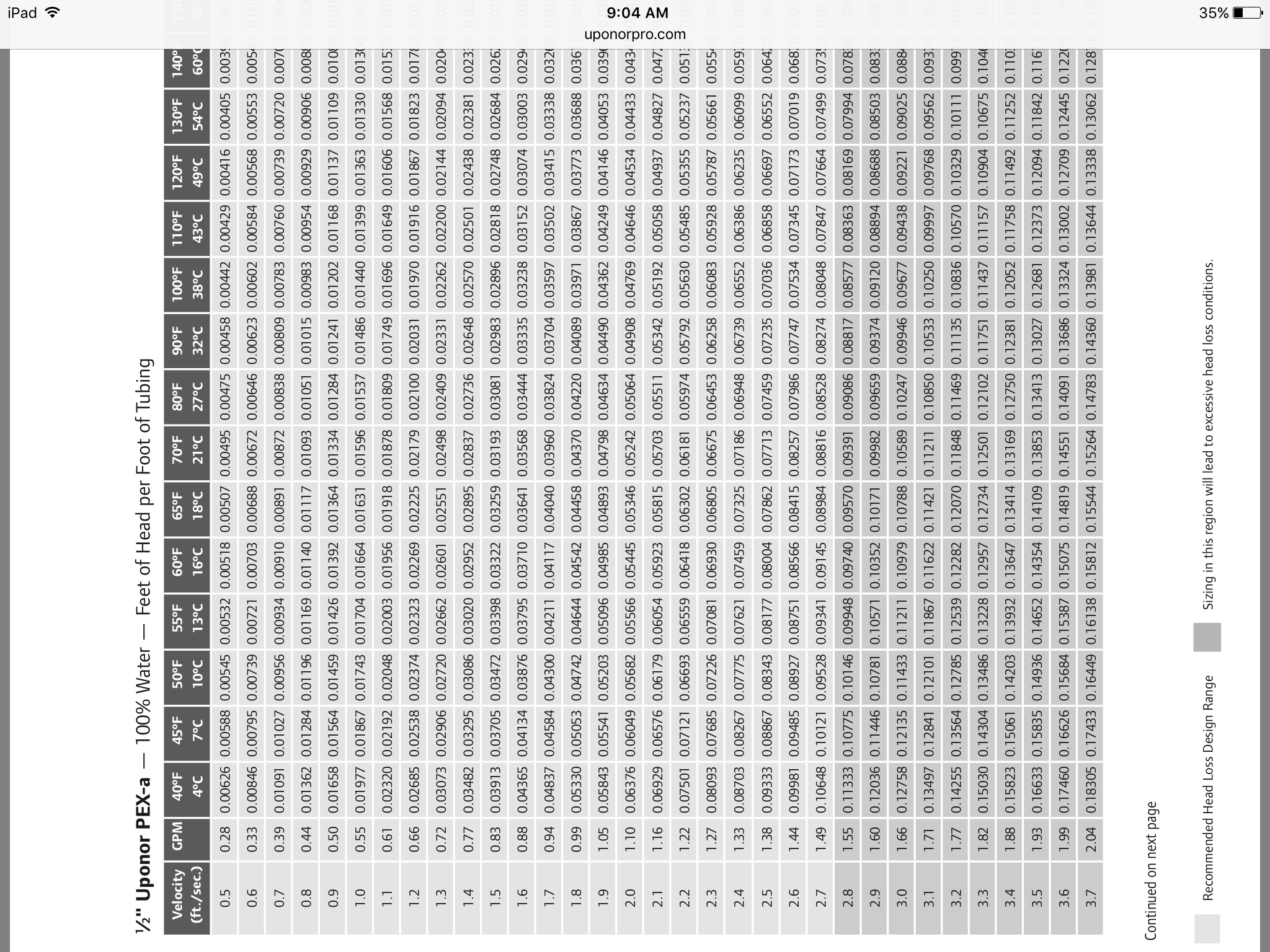
Plug in some of your loops to the formula I posted. Using different delta ts, or flow rates. You will see that even changing a delta from 10 to 12 drops the required gpm considerably. Then check the head loss for that gpm on your 1/2" pex loops the head drops dramatically. Will you notice a delta of 12 verses 10 under foot?0
-
Gordy I could only drop DT down to DT15 no smaller increments but that worked well, i also played around with the lops and shortened them. pretty significant change
Z! 1.18 fl/3.6 hd
Z2 1.49 fl/ 6.7 hd
Z3 2.13 fl/ 5.8hd
Z4 2.4 hd/ 5.9 hd
total 7.19 fl/ 6.7 hd
So that was good enough top put me right in the middle of that DT Taco 2218 curve.
But this loop cad is buggy and even i can see there are errors but i couldn't get them out they seem not to show up in all views so im hoping its ok.
One thing i dont understand is although i put in a water temp of 121 its showing different water temps for different loops so while i thought i was forcing it to hold that temp i dont think it is ill have to research, free trial expired just as i saved the last report but it says i can still play with it just not save or export so i may be able to understand what its doing with water temp.0 -
You don't have to use the program to drop deltas. Use the formula I gave you. I don't know if I would trust a free trial periods calculations.0
-
Maybe this was given on another thread, but what type of radiant floors are you installing?0
-
a home made warmboard 3/4 x 12" ply rips gapped for the tubing with aluminum flashing under and 3/4" t and g hardwood over.
i think it dropped the deltas fine I just dont understand what its doing about water temp In my mind pick a average water temp and adjust between zones with flow but also raise that average temp up and down with the outdoor reset but what do i know water temp seems to be a mystery.0 -
Are these homage plates? Do they fit snugly around the tubing?is it heavy gauge aluminum?0
-
A new idronics some good reading before you get to involved.
http://www.caleffi.com/sites/default/files/coll_attach_file/idronics_19_na.pdf0 -
Thanks for the link Gordy going to read it now.
Its8" wide aluminum flashing laying flat under the sleepers and tubes, not ideal, i started with a 3/4 rod welded to a angle and tried stamping it in but was difficult and gave that up. A while back when I first described it a few people derided my little scheme but someone chimed in that he had seen it in operation on a job he piped and it had performed pretty well, we shall see. Im spray insulated from below and loop cad had such a composition which i used. Im actually more worried about how much stuff the tenants have crammed in their apts will it block all the heat . next time i will pay for the real deal. However figuring out how to run tubing, leaders particularly] and still be able to nail down hardwood is so difficult, radiant ceilings might be worth considering. siggy didnt give a real comparison in the book but i see you mentioned them. whats your thought on them?
looking again at the vt2218 curve and new flow/ head calcs it looks to me like i might be able to squeeze DT 12 or 13 out of that pump is delta 15 v delta 10 a big degrade?
starting to get the headers at least installed, are drains right above valves all thats needed? or would you put checks spring? swing? on both supply and return risers, or if im back to zone valves do i even need check valve on risers?
One thing i like about that DT pump is it seems to simplify how i think about the system i dont need to think about translating into flow and then how that changes things I know if i give the pump a certain temp water its going to do what it has to to maintain the DT i set it as long as my flow head calcs are good i can push it right up to the cusp of its curve for design day which will give me plenty of curve below, [and it has a wider curve goes much lower good for small loads] But it also make in my mind simpler to be able to also raise and lower water temp as a separate issue say with a odr to the tempering valve between buffer and supply header. effectively widening my control band. Maybe the link you just gave me will throw that thinking in the garbage but thats my current idea how water temp comes into play.
0 -
Well that certainly is not a warm board knock off, but more a plate less sandwich method. Only about 1/8 of the circumference of the tubing is conducting btus to the aluminium. The rest of the tube is surrounded by air,and wood both insulators. conduction is king for heat transfer with radiant. Conduction drives down supply temps. Warm board gets away with 12" centers do to the continuous aluminium sheet which wraps the tubing by at least 1/2 it's diameter.
In your case I would have gone 8" centers, and left the flashing out. Your only advantage is your design day is a balmy 17 degrees.
Radiant ceilings are wonderful I have them love them. 1
1 -
yeah i had a "designer" when i started, who had some pretty drawings which at first instilled confidence, then i lost confidence after some further conversations, by then the tubes were on 12" centers i did ignore his advice to not waste money of oxy barrier tubing and at least i didnt use the hot water heater in lieu of boiler he swore by and a few other brilliant 70s ideas.yeah design days not bad in reality its a real rare day ocean effect. and im spray foamed and tripple paned. I did increase the spacing on the lower floor in loop cad to 9 which is the max for 1/2".
Looking at these taco iseries mixing valves with outdoor reset figure the buffer will be about 145 so ill need to mix down0 -
If you'd have listened to his ideas you would not need a buffer now . Those 70's ideas are not always very dumb . Of course there is the fact that you are in NYC where everything needs an H Stamp that is to do heating . I just had to design a floor warming system for another from the forum . Yep , had to use an 80K boiler to cover DHW . Also needed to add a 2 pipe buffer to use 10,000 BTUh at 5* . HTP Phoenix with 2 circs an Iseries ODR and an HX would have been great .
Did he recommend the sandwich method you used ?
Did he recommend a water heater or something like an HTP Pioneer ? Very careful design and install could allow for non barrier tubing using something like that . VERY CAREFUL , might I add .
You might try being a bit less dismissive of good advice . You have questioned alot of advice that has been given . Might I suggest really researching what you've been told before asking the next question ?You didn't get what you didn't pay for and it will never be what you thought it would .
Langans Plumbing & Heating LLC
732-751-1560
Serving most of New Jersey, Eastern Pa .
Consultation, Design & Installation anywhere
Rich McGrath 732-581-3833 1
1 -
No i get that my other house is a log cabin in the rocky mountains with a lot of 70s mother earth news technology and some of it with a little tweaking is still great. There i built a hydroelectric system and have been using permanent magnet generator for a decade, that system has a hydrogen electrolyzer i make hydrogen gas from with excess electricity, and my hot water heater i built a convection coil from the wood stove and another up to solar panels. there's a passive storage green house. i make ethanol in a still from jerusalem artichokes.to run my car and soon my airplane when its finished, and am trying to figure out how to make kerosene from pine slash.so i get low tech.I like low tech. and i like old geysers that know low tech im pretty much one myself.
But I got the impression he was an old guy that had been doing simple systems on rural cabins for people on real low budgets and while on my rural cabin it might be just the thing it wasn't what i wanted on a multi million dollar five story brooklyn townhouse.Partly because it has tenents and i want to be able to be away part of the year when i retire soon so it cant be a system only i can figure out.
The other thing is those conversations were almost five years ago when i first started the renovation, the hot water heaters he was talking about then are not whats now available at that time the wisdom was they would fail too soon.I think i came up with the sandwhich plan when i realized warm board must have gold heat plates and that you would still be cutting the **** out of it to make it work around anything other than a wide open room.next floor i will at least buy some molded heat plates.
Part of the problem current problem is,it was back then that this website convinced me that the TT110 was the boiler of boilers now there are options like 10-1 and other things. I could not find suitable heat calculators for my type of construction so was guesstimating conservatively, I am still skeptical it will perform as well as loopcad says, so i thought a used boiler prudent until the reno complete. also TT claims a 5.5 - 1 turndown my math says 110 / 5.5 = 20kbtu not 30kbtu so that didnt help. but mainly im working full time while also serving as the architect engineer PM and master of about 30 different trades on my renovation project so its just in time engineering. i figure out enough to hopefully not box myself in the future.
I dont think i have been dismissive at all I have been grateful particularly you, hotrod, and gordy. i have written you directly to thank you for that drawing and asking for clarification.
But questioning i must do. first because if you read the threads from my perspective you guys do not always agree, that's not uncommon for competent pros to have different approaches But its up to me to figure out why and decide how each will impact my specific needs which cant all be detailed in a blog post. I get that its frustrating to have someone that obviously doesnt know as much as you question things but it cant be helped.
Also its hard to know whos even competent to answer questions in a format like this until some questioning, i have upbraided one poster at least who was nothing more than a homeowner with an opinion.
Also While i dont pretend to be an ME, radiant designer, or even master plumber I have been a union HVAC mechanic, foreman, and super mostly on very large commercial NYC projects tin side for 35 years and held general contractor license and have renovated or built from scratch half a dozen buildings doing every trade myself so I know enough to get into trouble in a situation like this.
So i have to understand clearly why the expert is telling me to do it a certain way and not another way.
example i decided you three were competent and after a lot of back and forth it was clear you were all agreed on two over four pipe buffer configuration, i even found an article more recent than ed 3 from siggy talking about his noticing euro buffers were usually two pipe these days. After a week though no one had explained exactly how it worked i asked several specific questions several times but didnt get answers. I tried to make clear i was not questioning but only trying to understand but it was clear you guys were getting irritated. i was sure you guys were right but i wasnt going to pipe it without understanding the theory, or the exact concerns of the piping. Oh yeah i understood oversized headers, I knew the boiler side pipes cold be smaller but not if they had to be, it wasnt clear if there was a specific way they had to tie together at the buffer, and a lot of other things about how the water acted under certain situations, But it wasnt enough, so i was half decided to give up on the two pipe even knowing it was almost certainly the better way to go, before i decided to give up on the buffer entirely[ at least i think i will get this 10-1 modcon because the buffer and mix valve is half the cost and if i can get a bit for the TT110 and smart 30 and trim ill be in the same place] But heres another example some of you have said buffers are always great and others that they are always a fix for a bad design. I originally became enamored of them because i didnt want to run a primary and secondary pump every time a small zone called for heat but TT had a minimum flow.When i realized it also was maybe the best dirt and air remover and was the most complete hydraulic separator and would allow small zone i was intrigued.0


Categories
- All Categories
- 87.7K THE MAIN WALL
- 3.3K A-C, Heat Pumps & Refrigeration
- 59 Biomass
- 430 Carbon Monoxide Awareness
- 127 Chimneys & Flues
- 2.2K Domestic Hot Water
- 5.9K Gas Heating
- 121 Geothermal
- 170 Indoor-Air Quality
- 3.8K Oil Heating
- 79 Pipe Deterioration
- 1K Plumbing
- 6.6K Radiant Heating
- 396 Solar
- 16K Strictly Steam
- 3.5K Thermostats and Controls
- 56 Water Quality
- 51 Industry Classes
- 51 Job Opportunities
- 17 Recall Announcements