Run a C-Wire to #2 on a Taco Valve? Other location?

I have a Weil-Mclain Gold CGa Boiler with two Taco Zone Valves (one thermostat per).
I like many others, want to get into the Smart Thermostat world. I'm specifically looking to install an Ecobee 3 thermostat - starting with one, and adding another in the future.
I only have a heating system. I live in Alaska - no need for AC or anything else. Hence, I have two wires going to the thermos. Red going to R. White going to W. Luckily for me, there's a spare Green wire on both ends that I want to use for the common.
I've read the following:
1. Connect a common wire to #2 on the taco valve that goes to your corresponding thermostat.
2. Connect a common wire to the C at the transformer inside the boiler.
This may make me sound more of a "newb" but using a multimeter, I can get a constant 24v when using one lead on #2 of a valve and grounding the other lead - regardless of when calling for heat. This would make me think that this would be a good location for a constant - however, I can get the same when doing the same thing on the #1 location on the valve.
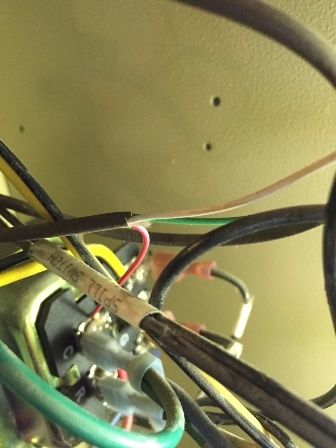
A couple of poor photos:
First - how the wires go into the transformer. The WHITE wires from each thermostat go to a nut. From the nut a RED wire goes to the C on the transformer.
Boiler
The RED wires from the thermostats connect to #1 on the Taco Valves.
Taco Valve
I'm leaning towards the #2 on the Taco valves - but any assistance is most appreciated!
Comments
-
You have to be careful, you should have 2 transformers, 1 on the boiler for it's controls, may be integral to the aquastat, the other powers the ZV's.
Taco uses 3 terminals to save money, they put the commons on 2, 3 is the end switch, #1 is the hot from the thermostat which would be the W terminal.
R goes to R on thermostat, W from tstat goes to 1, you can't go to ground for testing unless the transformer Common is grounded, it's a separate circuit so you have to go off C for all testing., you could power the Ecobee off R-C from the transformer that powers the ZV, don't use the aquastat transformer or you'll lose it.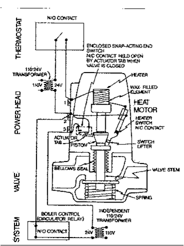
0 -
The 2 commons from the 2 transformers wired together will ignore eachother, if it's wired in any way say goodby to both transformers, the tstat, and possibly a few other items , you'll know instantly0
-
Hey - thanks for the quick reply.
I'll investigate a little more, but this is what I'm seeing.
W from the thermostats are going to C on the Transformer. They come together outside of the boiler at a nut, and then a Red wire from the same nut is ran inside the boiler to the C.
The transformer has a C and an R on one side. A W, G, and Y on the other.
The Red wires (which are connected to R on the thermostats) are connected to their respective Zone Valve's 1. I'll have to recheck how #2 is wired, but from what I recall it sure seemed like it was a white wire on both valves going to a nut. I'll have to re-check to see where it's ran into.
Yes, the last thing I want to do is blow any transformers, thermostats, etc., etc.
I can't for the life of me find the 2nd transformer. I agree with you, there should be one, but I've yet to locate it.
Are you saying, if I can locate the transformer and am sure it is for the ZoneValves that I should be able to use the C off of it to power the Ecobee? Just do not do so on the transformer that powers the control unit.
Is that correct?0 -
Sorry - one last question - when looking for a second thermostat - should I theoretically be looking outside of the boiler? I'm certain, based on reviewing the boiler's manual that the transformer inside the boiler (I remove the front panel to access) is for the boiler controller.
Is there any reason I wouldn't be able to run the Common wire directly off the zone valve's #2 location?0 -
I think you meant "second transformer". In general the boiler's trans isn't used for the taco transformers, but you have the eyeballs
Can't you just take your r and c from the tran, go direct to stat, and your w some back to 1. 2 goes to C. 2 and 3 goes back to boiler. When in doubt get a 5 dollar"popper fuse", cheap insurance. If it's doesn't pop you can call it a victory. If you want to be extra special get an amp reading
Yes you should be able to run off the 2 terminal, if everything is normal. The valve is a power consuming device just like your stat is. It just may be neater to run from the trans0 -
Well...this is what I do know - 100% since I traced the wires.
Red is connected to R at the T-Stats. Red is the connected to it's respected zone valve at #1.
The White is connected at W on the T-Stats. At the boiler end the come together at a nut and from the same nut a red wire goes inside the boiler and is connected to a point labeled C.
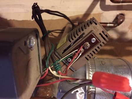
Here's another photo of the same pictures above with annotations.
Valve
Boiler
From inside the boiler I need to determine where the Green and White wires are terminating at. This 18/3 wire is not going directly to a thermostat but is attached to the zone valves and t-stats, from what I can surmise.
I'm not sure what a popper fuse is - I can easily install an in-line fuse though that will break if needed. Which amperage should I select? 5a to be safe?
Also the transformer's model number is this:
Honeywell R8285D 1000 DPST Switching Relay 40VA Transformer 120V - also called a Boiler Control Center. Here's what it looks like:
https://images-na.ssl-images-amazon.com/images/I/919ubYbRzlL._SL1500_.jpg
Thanks again - this is awesome to get such great advice!
0 -
A popper is a handy device when you're having a bad day. If you overload the button pops. Simply push back in after you corrected the problem. But yes, use some 5 amp fuses if you're unsure.
When talking wires try to say where the wire came from and where it's going. Try not to say " red is going to r on trans", that's not a compete explanation. Say, transformer: r goes to stat's r and transformer c goes to taco term 2. Your trans r should not be going to taco term 1.
Your taco 2 and 3 should be in series between the two tacos and then to the tt on the boiler. The boiler needs just two wires to fire up.0 -
It might be wise to wire those high current draw ZVs through a relay box.
Some of the relay boxes have a common on the t-stat connection to ease the connection of power stealing stats. You really want 3 wires going to the Ecobee as it will leak about 18V back, in the off position, on a two wire install.
With a relay box you get fuse protection and simplified wiring, little to no risk of letting the smoke out of electrical components.

Bob "hot rod" Rohr
trainer for Caleffi NA
Living the hydronic dream0 -
Whoops. Sorry Gary.GW said:A popper is a handy device when you're having a bad day. If you overload the button pops. Simply push back in after you corrected the problem. But yes, use some 5 amp fuses if you're unsure.
When talking wires try to say where the wire came from and where it's going. Try not to say " red is going to r on trans", that's not a compete explanation. Say, transformer: r goes to stat's r and transformer c goes to taco term 2. Your trans r should not be going to taco term 1.
Your taco 2 and 3 should be in series between the two tacos and then to the tt on the boiler. The boiler needs just two wires to fire up.
Hopefully this will make more sense - again, I need to take another look at everything regarding where all the wires are going but this is what I know.
Heat only and 2-wire only install. Nothing else. I'll describe how one thermostat is wired and where those wires go since both are set up exactly the same.
From the Thermostat -> Boiler:
R Label at Thermostat -> Red Colored Wire -> #1 Labeled Connection at Zone Valve. This is where this wire terminates
W Label at Thermostat -> White Colored Wire -> Red Colored Nut -> Red Colored Wire -> C Labeled Connection at transformer inside the boiler. This wire is not connected anywhere at the zone valve or anywhere else.
The Green Wire at #3 and the White Wire at #2 on the Zone Valves is where I'm fuzzy on. I need to re-investigate to determine how they're wired and where they terminate.
Hope this makes some sense. Sorry again.
I don't know if this matters or not...but in just reading the manual, this is a standing pilot boiler - not a spark-ignited. It doesn't have a control module.0 -
pretty sure you need 3 wires, a common to make an Ecobee behave.
Sometimes there are extra conductors tucked into the wall behind the stat, check the wire on both ends to see if you may have additional conductors.
There is a work around with an "extender".
Bob "hot rod" Rohr
trainer for Caleffi NA
Living the hydronic dream0 -
HR he says he does have 3 wires, a spare green.
I'm kinda unsure how you have 24v on term 2, something is backwards.0 -
Sounds like the t'Stat is breaking the common side of the transformer, not the hot side.0
-
I have seen more of these operating at 48 volts than on 24. These actuators are made too good for thier own good.hvacfreak
Mechanical Enthusiast
Burnham MST 396 , 60 oz gauge , Tigerloop , Firomatic Check Valve , Mcdonnell Miller 67 lwco , Danfoss RA2k TRV'sEasyio FG20 Controller
 1
1 -
They are tough actuators. But how many transformers are lost, because few realize the comm on not the hot goes through the end switch.0
-
Mike - from everything I've read I tend to agree with you. It "seems" like the W from the thermostat and the R are flipped at where they should be connected to at the boiler.
With that in mind, I think I'm going to follow the advice of installing an inline fuse as a bit of protection and connect the common to the #2 terminal at the zone valve. Seems to be the safest thing. Either a) the fuse will blow, b) it simply won't work, or c) it will.
We're talking about a two wire install - I'm not experienced in this but I know enough about electrical and wiring that this can't be THAT difficult.0 -
Two wires??? I thought you had 3?
You're right it's easy, frying a trans is easy too.0 -
It's currently a 2-wire install. The third wire is free that I'd like to use as the constant wire - it's not currently connected to anything. After getting the ecobee installed then yes, it will be a three wire installation.
No, you're right. I'm getting ahead of myself. Short of contacting a hvac person and having them come out I'm out of ideas. I like to DIY so that's why I'm trying to figure out the best way to do this.
There's only one transformer at the boiler. There isn't a second where I would be able to determine that one is for the zone valves and one is for the boiler control - that's where I'm stuck.0 -
Will this help? I created a drawing of where all the wires are going.
Note - obviously it's not ALL the wires, but I did add a few that seemed like they may help discern the best location to place a common wire.
I know it looks a bit messy too - just drawing to be as comprehensive as possible.
Again - thank you all for assisting! If I can get this figured out I will be ecstatic!
Here's the drawing:
Drawing0 -
Ok 1 transformer. A 40va transformer can power your 2 zone valves and boiler. If any of the valves, and or boiler start drawing more power, and they will, you're going to have problems! The guys here know this, that's where the second transform comes into play. Now where do the wires on terminal R , C and G, of the boiler transformer go?0
-
Ok that makes sense, I thought we were talking 2 transformers. Makes sense now that drew it out, boiler r runs through the taco 2, then back through the 3 to the boiler G. You have the good old Fan Center, not a simple TT connection.
I don't think I've ever seen tacos without their own trans.
You need to get funky becasue there's no r at that stat, nor will it work if you do run an r
You need a relay and another trans, or get the panel HR mentioned0 -
Ahh - ok, now I think we're getting somewhere.
All C is going to is 1) the white wires on the thermostat and 2) what appears to be a ground. It's a green wire connected to a screw on the transformer/relay.
In order to definitely tell where R and G go to I'll need to pull off the transformer/relay module. I can say they are going behind it - what I don't know is if they are being connected somewhere else in the module or being connected to wire nuts and then going out to here:
http://gdurl.com/Houv
It's a junction box. The wires inside are either going to A) a cartridge circulator or b) line power.
My *guess* is that the R, at a minimum is running to line power.
I also found the manual to the transformer/relay. Here's the page that contains the schematic for the one we have (Figure 5):
http://gdurl.com/6n7M0
Keep in mind, our thermostats aren't wired the same way - but it may give some insight on the other wiring.
If I can confirm that R on the transformer/relay is going to line power - that's NOT the one I want to use as the common correct?
That narrows it down to C or a location at the zone valve itself?0 -
-
So GW - I won't be able to run a constant wire at the existing transformer or at one of the terminals at the taco valves?
What about using one of those "add a wire" modules?
https://www.amazon.com/Venstar-ACC0410-Wire-24VAC-Thermostats/dp/B0013LVDQA
The ecobee even comes with something similar called a "power extender" but I don't think it can work with my configuration.
Starts at page 10 (not that I expect you guys to review all this - I've asked enough as is)
https://www.ecobee.com/wp-content/uploads/2013/12/ecobee3_InstallationGuide.pdf0 -
I don't have any experience with the add a wire
Your boiler has what we call a Fan Center, don't bother taking it apart. R to G brings the boiler on
Most heating appliances have a control board. Some cheaper heating appliances have a Fan Center, to keep costs down
If you had a more normal boiler control, this process would be relatively easy
A normal boiler has what we call a TT terminal, and normally terminals two and three on the Taco would connect to TT
Your situation is different, 24 volts must travel through some sort of switch then make its way back to G on the fan Center
You can't have power on number one and power on number two, that won't work with taco.
I'm sorry to say it's not as easy as we all thought it would be. You need to get creative with relays to make this work, most DIY folks aren't comfortable with that0 -
Well bummer - I am glad that I posted my question here though!
It doesn't sound impossible - just a job best left to the pros.
Thank everyone!0 -
Here's how I would do it, assuming the transformer is rated 40-VA (volt-amperes) or higher:
R on transformer feeds all terminal 2 locations on zone valves.
Connect all terminal 3 locations on ZVs to terminal G on transformer/relay unit. This will send 24V to the relay coil when a ZV opens. Either ZV will operate the relay when the ZV "end switch" connects terminals 2 & 3 as the valve opens. The 24V path is: R on transformer to 2 on ZV, thru the end switch, then back out of the ZV via terminal 3 to G on the transformer/relay unit, then thru the relay coil whose other end is wired to C on the transformer. G may or may not also connect to the gas train (spark module and gas valve) to send 24V there.
The thermostats connect to terminal 1 on their ZVs and the other wire coming back from the stats connects to C on the transformer. The 24V path here is: R on transformer to 2 on ZV, thru "heat motor" coil in ZV out to thermostat via terminal 1, and back from thermostat to terminal C on transformer.
It's important to remember that the end switch on three-wire zone valves is not a "dry contact" the way a thermostat is, "dry" in this case meaning an internal switch contact with no voltage applied to it from within. Terminal 3 on these ZVs sends 24V OUT to operate something rather than accepting and switching voltage from some other control. Therefore, it is best to have the ZVs send their Terminal 3 voltage output to a relay (called an isolation relay) which can then switch something else. Where there are more ZVs than a 40-VA transformer will handle, some people try to "phase" two separate transformers to avoid using the relay, but it's way too easy to fry transformers or control boards this way (ask me how I know that). Fortunately, in your case, the 40-VA transformer and the relay you already have will do this just fine.
Baltimore, MD, USA
Steam, Vapor & Hot-Water Heating Specialists
Oil & Gas Burner Service
Consulting 1
1 -
Part 2:
With the Ecobee or any other thermostat that will accept a 24V power feed, you need to establish a path between terminals R and C on the transformer to power the stat. The usual corresponding terminal designations on a stat are R and C, but this setup reverses the letters when you hook up to the stat.
With your 3-wire ZVs, the thermostat switching takes place on the C (on transformer) side of the heat motor coil in the ZV.
In this example I'll assume that the wire from ZV terminal 1 to the thermostat is red, and the wire from the stat to transformer terminal C is white, and there is a green wire which we will use for the power feed. I will also assume that the heating contact terminals on the Ecobee are R and W, and that the common wire connection which powers the stat is C. Note that I've never actually tried it this way, so double-check the terminal designations and verify things with a voltmeter before actually hooking it up.
R on the stat is common to both the switch contact and the power feed, so in this example it will connect to the white wire that goes back to terminal C on the transformer.
W is the other side of the switch contact, so it will connect to the red wire that goes to terminal 1 on the ZV.
And C is the other side of the power feed, so it will connect to the green wire which goes back to the R terminal on the transformer. If convenient, it can connect to terminal 2 on the ZV which goes back to the transformer's R terminal.
Since this is alternating, rather than direct current, the reverse polarity should not matter. You can arrange the colors any way you want that makes sense. Let us know how you make out.Baltimore, MD, USA
Steam, Vapor & Hot-Water Heating Specialists
Oil & Gas Burner Service
Consulting0 -
Which model Ecobee do you have? I think the Ecobee 3 comes with one remote sensor, battery powered. It would allow you to mount the stat where you could get new wiring with enough conductors, then just place the sensor in the room to be controlled. If that wire is part of you issues.
Then run the stat from a smart phone to make adjustments.
I believe Ecobee also supports IFTTT, "if this then that" so you could run some unique logic control with that feature also.
I think a relay box will clean up and solve all the wiring questions. I'll check with our tech support for any other glitches.
I know one of the competing stats draws a high current when it goes into a batter recharge mode, that combined with two high draw zone valves could cause transformer issues.
Honeywell claims their NEMA 2 transformers can handle a 200% over rating condition for an undefined "short period". If you go the route of two transformers, don't get a cheap import.
VA = volts time amps
Two Taco 570 series at .9 A= 43VA plus the draw of the t stats, .25A I think.
I have seen those ZVs pull as high as 1.2, so 24V X 2.4= 57VA plus the stats 1VA, might be wise to use a 60VA transformer.Bob "hot rod" Rohr
trainer for Caleffi NA
Living the hydronic dream0 -
Wow Steamhead, thank you so much for the informative post!
And yes, your description is accurate. The White wire connected from the thermostat at W connects to the C on the transformer.
The Red Wire connected at R from the thermostats connect to terminal 1 at the ZVs. Terminal 2 from the ZVs connects to R at the transformer.
So, if I understand you correctly, I should be able to run the Constant wire from the Ecobee to either R at the transformer or at terminal 2 at the Zone Valve?
I will say - all the major outlets are having a sale for the 3rd Gen Nest, so I went to pick one up since they claim they can run w/o a C wire.
Hooked up and seems to be working great. I guess the way it works without a constant is that it will pull the power from the R connection - pulsing the boiler (ie, turning it on) momentarily when it needs to charge it's internal battery. As long as it doesn't have to do so all the time, this end up being the safest solution.0 -
Just check to make sure that it isn't leaking voltage back. We have tested quite a few brands of power stealing stats connected with two wires and found some stats "leak" up to 18V when in the off position. It's trying to use one of the two wires as it's path to common.
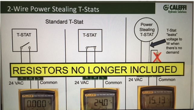
This example shows one leaking back 15V in the off mode.
It can show up as a buzzing relay, or flickering lights on a zone control.
Originally the Caleffi relay boxes requited a pull down resistor be added to shed away that stray, we have engineered a fix on the boards now, no more resistors needed.
Last we talked to Nest you could not run with only two wires, successfully. Maybe they include an "add a common" fix now?
A volt meter is all you need to test if you have this stray current.Bob "hot rod" Rohr
trainer for Caleffi NA
Living the hydronic dream0 -
some addition installer info


Bob "hot rod" Rohr
trainer for Caleffi NA
Living the hydronic dream0 -
Hi Hot Rod -
How would I check with the voltmeter (which I have)? Do I check at the thermostat or at the boiler?
Looks like I'd put one lead on the W and one on the C - just not sure WHERE I do that.
Yeah, I'm not sure re: Nest. The box says in many cases you do not need a C wire, as does their support pages on the nest.com website.
Thanks!0 -
Yup Hot Rod - I read that as well which made me initially purchase an ecobee (haven't tried installing it yet). Figured both needed a c-wire and I liked the ecobee more.
BUT the nest went on sale yesterday. I picked one up thinking "hey, it's worth a try. If it doesn't work then I'll just return it".
So far so good though, I'm going to go check the volt leakage here in a minute though - if there's an issue with that then back it goes and I'm back to square one.0 -
So I tested at the thermostat because - why not?
The nest's contacts are embedded in plastic so it was hard to fit the voltmeter leads to where I can actually test.
But assuming I did, it looks like it's drawing about 4 volts. 0
0 -
That's correct. The Nest should work the same way, so you shouldn't need an "add-a-wire" or similar gadget.jcarlough said:So, if I understand you correctly, I should be able to run the Constant wire from the Ecobee to either R at the transformer or at terminal 2 at the Zone Valve?
Baltimore, MD, USA
Steam, Vapor & Hot-Water Heating Specialists
Oil & Gas Burner Service
Consulting0 -
Do you think this leakage would be enough to activate a Taco ZV heat motor?hot rod said:Just check to make sure that it isn't leaking voltage back. We have tested quite a few brands of power stealing stats connected with two wires and found some stats "leak" up to 18V when in the off position. It's trying to use one of the two wires as it's path to common
(snip)
It can show up as a buzzing relay, or flickering lights on a zone control.
Baltimore, MD, USA
Steam, Vapor & Hot-Water Heating Specialists
Oil & Gas Burner Service
Consulting0 -
Depends on how much, if any voltage leaks. That is just a heat motor so any power will start to warm it, I would think? It may not be enough to open it to end switch, but it could open enough to allow some un-wanted flow.
Maybe Taco has some experience with this, I think they include wordage about power stealing stats in the manuals.Bob "hot rod" Rohr
trainer for Caleffi NA
Living the hydronic dream0 -
The one on their website doesn't mention this, but it's pretty old:
http://www.taco-hvac.com/uploads/FileLibrary/100-3.2a.pdf
But using a common wire as described in this thread, or a zone valve relay panel, should sidestep the problem.Baltimore, MD, USA
Steam, Vapor & Hot-Water Heating Specialists
Oil & Gas Burner Service
Consulting0 -
http://www.taco-hvac.com/uploads/FileLibrary/102-391.pdf
This mentions a pull down resistor with the relayBob "hot rod" Rohr
trainer for Caleffi NA
Living the hydronic dream0 -
Yeah, I don't know...the Nest seems to be working real well so far. It calls for heat appropriately, I haven't heard any buzzing or anything funky coming from the boiler. I was in the garage for three/four hours last night as well (where the boiler is) and doesn't seem to be turning on/off regularly either (we normally don't have to run the boiler during the summer in Alaska).
I'm thinking it still may be best to run the C wire anyway - but I'm also thinking "if it ain't broke don't go messing with it".0


Categories
- All Categories
- 87.6K THE MAIN WALL
- 3.3K A-C, Heat Pumps & Refrigeration
- 59 Biomass
- 430 Carbon Monoxide Awareness
- 125 Chimneys & Flues
- 2.2K Domestic Hot Water
- 5.9K Gas Heating
- 121 Geothermal
- 170 Indoor-Air Quality
- 3.8K Oil Heating
- 78 Pipe Deterioration
- 1K Plumbing
- 6.6K Radiant Heating
- 396 Solar
- 16K Strictly Steam
- 3.5K Thermostats and Controls
- 56 Water Quality
- 51 Industry Classes
- 51 Job Opportunities
- 18 Recall Announcements