Welcome! Here are the website rules, as well as some tips for using this forum.
Click here to Find a Contractor in your area.
If our community has helped you, please consider making a contribution to support this website. Thanks!
Common supply pipe, multiple returns, possible to balance?

My monoflo has a 2" supply,
Zone 1 - split 1.25" returns. 15GPM (7.5GPM each run). Taco 0034EPlus.
Zone 2 - 1" return. 5GPM. Taco 0015E.
When they both run, the combined flow is 18GPM.
What's the simplest way to make the combined flow 20GPM?
Monoflo rads are tricky to balance, changing flow rates don't help.
Comments
-
The flow rates you need depend on the ratings of all the baseboard attached. With monoflow if you use the actual heat loss of the house to calculate the flow by converting btus to water flow needed you may not have enough flow for the monoflow tees to work well.
So I would add up the total BTUS of the radiation on each loop or on a split loop get the BTUs and divide that by 10,000 to give you the gpm you need. Then compare that gpm to the pipe size you have to see if it is reasonable that the monoflow tees will work and that the velocity is enough to move air around the system. That is the first step.
0 -
Did all of that in an excel. Total radiation is 200,000BTU, boiler is 180,000BTU. Heat loss for the house is closer to 180000BTU. Either 18GPM total or 20GPM works fine, as long as Zone1 Flow + Zone2 Flow = Total Flow
This being a monoflo system, first rad gets much hotter water than last. Closer rads needs to be throttled significantly. This produces a different result when one zone runs at a time compared to when both run which reduces the "balanced design flow" to each rad, which is the issue I'd like to solve.
0 -
First thing: what type of radiators is the system connected to? @EBEBRATT-Ed assumed Baseboard while I emideatly thought of wall mount convectors or recessed in wall convectors.
Second: How are you determining 18 GPM? Do you have accurate flow meters?
Finally: is there a particular problem you are trying to solve? Why do you need an extra 2 GPM? Are there some radiators that don't heat properly? I don't believe that an extra 2 GPM will make the difference.
Edward Young Retired
After you make that expensive repair and you still have the same problem, What will you check next?
1 -
@sixplex , need more details here. You say 2" supply- do all the individual radiator feed lines come off the 2" individually, or do they branch off and then feed the rads? If the latter, what size are the branches?
What about the return side? Does everything go back into a 2" return, or is it smaller?
Where are the flow-checks located?
 1
-
A few ways to increase heat output.
Increase flow rate. This increases average temperature across the heat emitter.
Increase supply temperature
Force convection by adding fans near the radiator or convectors.
If the house or certain rooms are under heated, look for ways to lighten the load in those areas. Insulated window coverings can help a lot.
Bob "hot rod" Rohr
trainer for Caleffi NA
Living the hydronic dream2 -
Did all of that in an excel. Total radiation is 200,000BTU, boiler is 180,000BTU. Heat loss for the house is closer to 180000BTU. Either 18GPM total or 20GPM works fine, as long as Zone1 Flow + Zone2 Flow = Total Flow
WOW… How big is this house? My 3 bedroom 2 story colonial was 1700 aq ft and required only 47,000 BTU on a lower that design day (I calculated 70F° @ 0F° when the official design for my area is 70°F @ 14°F) but that is my own home.
For a 180,000 Load calc you must have a 6000 sq ft home, or a home with no insulation.
Anyway, from your description, I picture your MonoFlo® design something like this
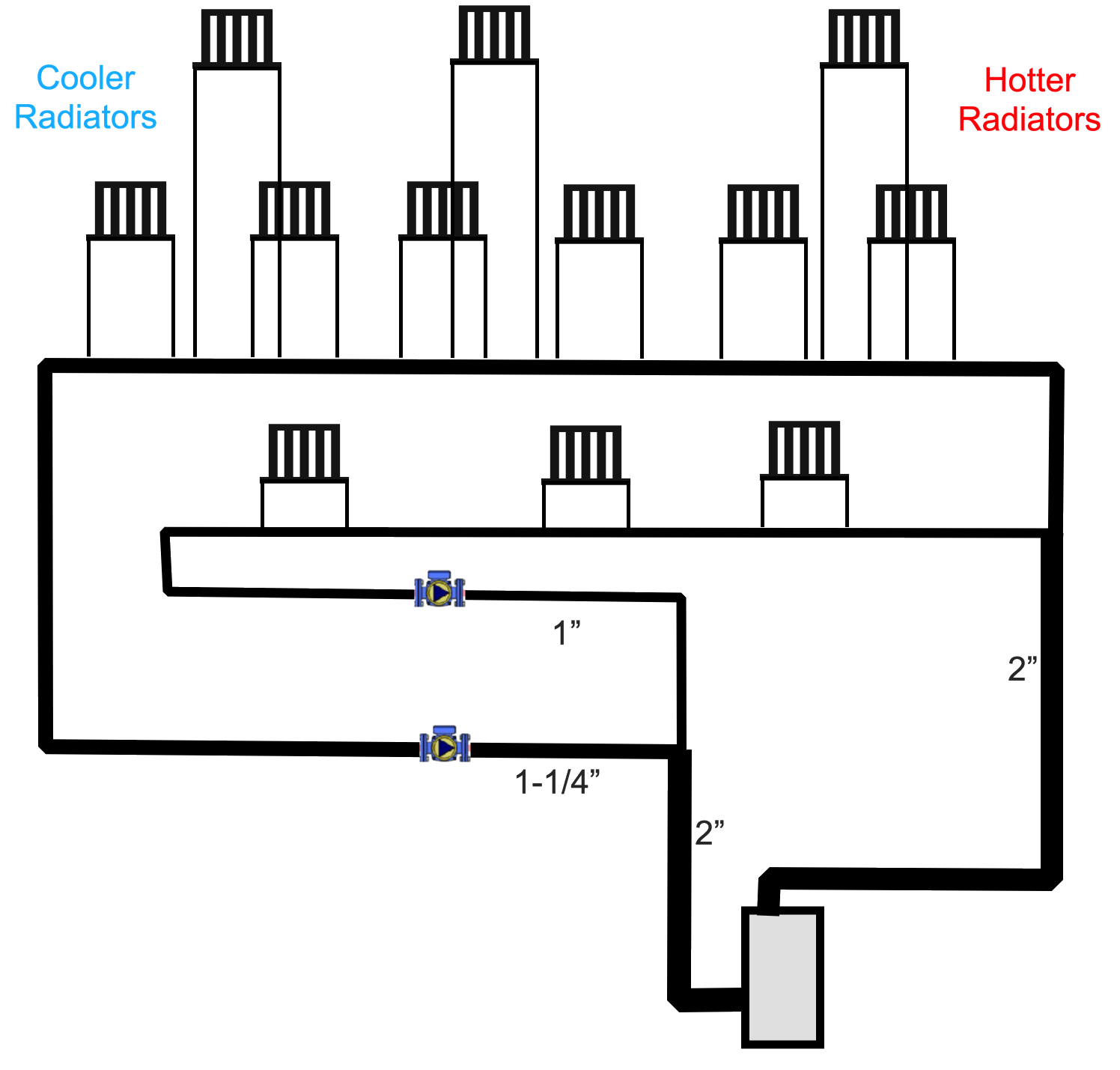
If this is not perfect but is close, then having cooler radiators toward the end of the loop is normal for this type of system.
The easiest way to balance the heat output is to adjust the dampers on the radiators in the warmer rooms. Closing a damper reduces the airflow through the radiator, which reduces its heat output. This allows the cooler radiators to continue heating their rooms while the hotter radiators put out less heat.
You can approach this from either direction, but sometimes it is easier to place the thermostat in the coldest room and adjust the dampers in the rooms that get too warm.
There is also a psychological advantage to this approach. It is easier to understand why you would want to reduce the heat output in a room that is too hot than to reduce the heat output in a room that already feels comfortable. The goal is to balance the system so all the rooms reach a comfortable temperature without some becoming too hot while others are still trying to catch up.
Edward Young Retired
After you make that expensive repair and you still have the same problem, What will you check next?
0 -
what kind of emitters do you have? if you have baseboard radiators or convector cabinets i would cover some of the element in foil or close the damper on the enclosure in the hotter rooms.
if you restrict the flow in an emitter with monoflo you restrict the flow in the whole loop so restricting the output of the hotter emitters is better than restricting the flow.
1 -
I guess there is no way to get the pumps on the supply side? It would be nice to have the delta P from those large circs added to not subtracted from the circuits.
Bob "hot rod" Rohr
trainer for Caleffi NA
Living the hydronic dream0 -
Goal: reasonably consistent GPM through each zone when each zone runs alone or both run together. Actual balancing comes after.
Reason: balancing at each radiator will behave differently at different flow rates through the zone, i.e. if water is flowing faster the last radiators will have warmer water, closest rads need less throttling.
Currently when the smaller zone's flow is reduced by some 20% when both zones runs, the bigger zone by 5%
0 -
Your diagram is spot on, it's more complicated but i don't think those details are relevant it's perfect for this.
The 2" section immediately after the boiler for the first 6 feet is 1-1/4" i imagine that's a big bottleneck when both pumps are bushings combined 18-20GPM, not sure how important this is.
Is there some magical ecm pump setting / different pumps, that will solve this?
1" zone runs on Taco 0015e set to medium constant pressure, with it's pipe throttled some to achieve the right GPM when it runs alone.
1.25" zone runs on Taco 0034eplus set to C2, constant pressure, it's pipe is throttled a bit too.
0 -
Pumping away in my case needs 2 higher CV zone valves, standard, common ones max out around 10CV, the higher ones are expensive additional points of failure I'd rather not add unless there is a very clear benefit.
I don't have any issues with air or noise, pumping away is awesome but apparently not super necessary for every system.
Will using a single pump solve my current issue?
0 -
Let me understand this : "The 2" section in your diagram immediately after the boiler for the first 6 feet is actually 1-1/4" in my basement. I imagine that's a big bottleneck when both pumps are bushings combined 18-20GPM, not sure how important this is." (Did I get that right?)
Yes that would be a bottleneck and if you actually get that 1-1/4" pipe to move 18 GPM. it may be a little noisy. The fact is that most of the circulator pumps that we use in residential systems are niot that powerful and will be restricted to moving less GPM when meeting with that type of obstruetion. That may be part of your problem.
As a rule of thumb a 1-1/4" pipe will move about 140,000 BTUh of heat (that rule of thumb is based on a 20° temperature drop and water moving at or less than 4 feet per second) When water moves faster that 4 feet per second in a pipe, you tend to heat the water flow like when you flush a toilet. Imagine that water rushing noise noise every time the thermostat calls for heat.
In order to keep the noise down to an acceptable level a 1-1/2" copper pipe can move 22 GPM at less than 4 FPS. That is more than enough for your two circulator system.
Edward Young Retired
After you make that expensive repair and you still have the same problem, What will you check next?
0 -
To clear some things up. Is the boiler output 180,000 or is that the input BTU?
Whatever the number is that is what the flow rate is based on.
If it is a 180K input X 82%= 147,000. So 14 gpm or so moves all the boiler can give you.
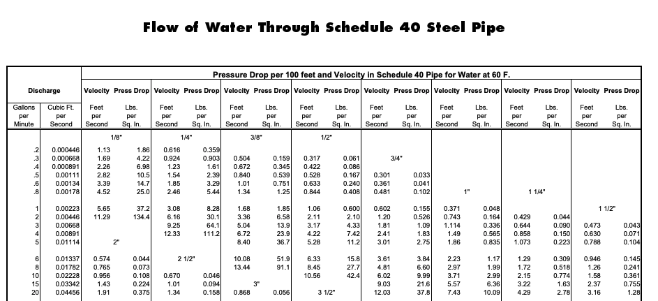
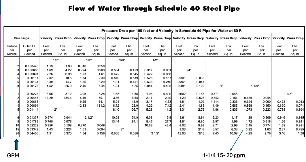
If it is 180K out I think 1-1/4 would still be adequate. Use the engineering tables from the pipe manufacturer, for the best data. This is for schedule 40 steel pipe.
20 gpm in 1-1/2" is 3.16 fps velocity, and 1.28 psi drop through 100' of pipe. There is a small correction for hotter water, this assumes 60°F.
Doesn't matter if you are 2" to the split?
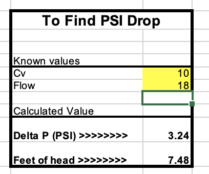
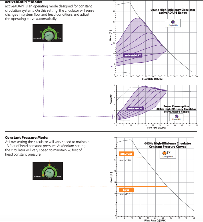
As for the ZV option , single pump, pumping away. A 10 Cv valve with 18 gpm= 7.4' head
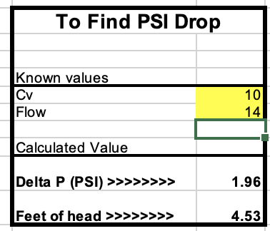
If in fact the boiler is closer to the 147K output
14 gpm= 4.5' head. not a big deal for the circulator you mentioned
Seems like the 00343 has plenty of fizz to get the job done? Auto Adapt would learn the ZV conditions, if you go that route.
 Bob "hot rod" Rohr
trainer for Caleffi NA
Living the hydronic dream0 -
Back in the 1940s and early 1950s when the majority of the MonoFlo® systems were installed, the industry didn't even know about primary secondary systems. Gill Carlson introduced the concept in 1954.
Edward Young Retired
After you make that expensive repair and you still have the same problem, What will you check next?
0 -
The boiler is 180,000net. 225000 input.
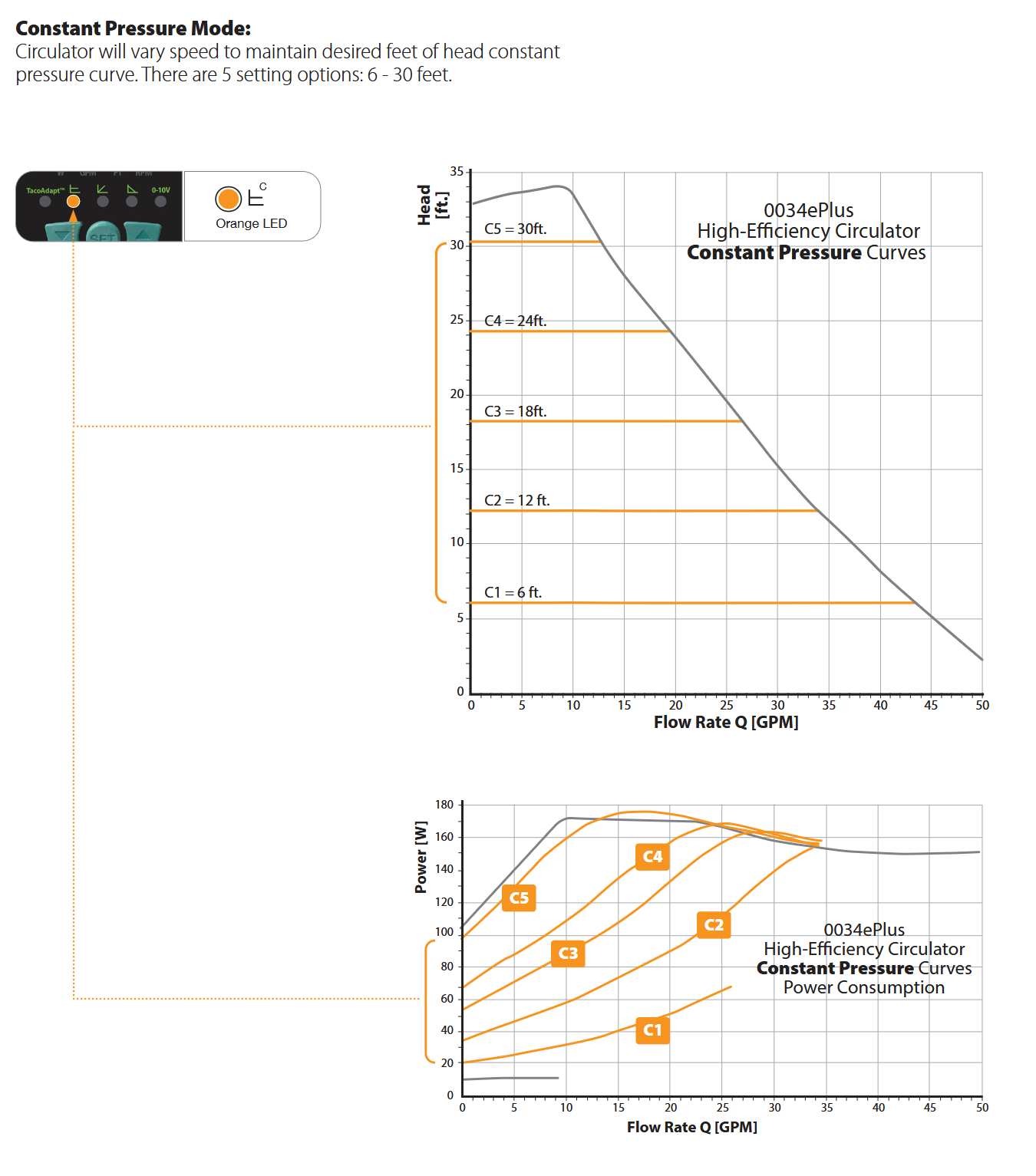
I have a Taco 0034e plus. It has even more options.
 0
-
Mistake was using the constant pressure mode, somehow i thought it was the right thing when two circulators are pumping in parallel and fighting one another.
Changed both circulators to fixed speed and now when both run it's within 5-10% of the sum of their individual flows.
0015e doesnt have infinitely variable fixed speed like 0034e plus so i had to set it to to max, and throttle with a valve.
0 -
TRV especially for near emitters?
0 -
the circulators should not fight one another if they are connected to a pipe sized to deliver the total flow of the pair? And with check valves there would never be back flow through an unpowered circulator.
You have more adjustability than ever before with ECM circs. There should be a setting that works.
Early Auto Adapt was finicky, but the algorithms have improved over the years and they seem much more “auto”
Bob "hot rod" Rohr
trainer for Caleffi NA
Living the hydronic dream0 -
The boiler output has a 1-1/2 port, the licensed hvac that installed put a 1-1/4 pipe in there for 18GPM needed to do 20F delta T. The 1-1/4 goes on for an equivalent length of ~10', hopefully once i resolve that i'll see an improvement.
I still need to address boiler protection, i was going to do it with ESBE VTC511 whose CV is 16, if i change 10' of 1-1/4 to say 1-1/2 and add a 16CV restriction i might be back to where i am now. The Caleffi equivalent is even more restrictive at 14 CV.
0 -
I doubt that section of 1-1/4 is costing you much restriction.
18 gpm in 1-1/4 steel pipe is under the acceptable 4 fps, and only a few ' head over 100' length. So your pressure drop in 10' is inconsequential.
If it is copper you are at 4.4 fps
No manufacturer makes valves in 1 Cv increments. So use a Cv calculator to see what a lower Cv does to pressure drop. You don't really want to oversize a valve as it loses adjustability.
Engineers call this valve authority. The valve should consume at least 25% of the system ∆P. Oversizing caused the valve to hunt, or oscillate. So with that 16 Cv valve on an 18 Cv load you are in a good spot.
Diverter tees by design add a lot of pressure drop to a circuit, depending on the size 23-70' of EL equalivlent length. So count up the diverter tees in your circuit. 12 one inch divter tees= 282' of pipe.
This is why monoflo design is so critical. And any modifications can throw it for a loop.
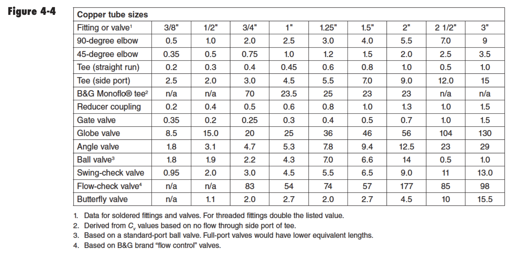
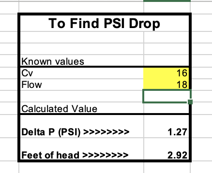
Here is 18 Cv through a 16 Cv device, 2.9' head
 Bob "hot rod" Rohr
trainer for Caleffi NA
Living the hydronic dream0 -
Is there an ECM mode that makes it pump harder when flow reduces / resistance rises?
1-1/4 (schedule 80 steel) might not be much but it's enough to restrict 18gpm down to 17 or so when both zones are pushing through that same pipe, if i add another 16CV restriction that 17 may become 16 or less.
As explained i need flow through each zone to be consistent at all times.
It seems to me primary secondary is the only clean way to do what i want.
0 -
how do you know what gpm you are flowing now?
This Idronics takes you through the steps to define a piping circuit , select a circulator, determine where the circulator is actually running on its curve. Also how the different ECM modes work.
Constant pressure or constant flow and when to use which one.
If you can’t see all the piping to define the circuit, add some balance valves that have a readout built in
If you adjust the pump speed or settings until you get adequate heat at the last radiator, does it matter what the gpm is?
Bob "hot rod" Rohr
trainer for Caleffi NA
Living the hydronic dream0 -
I use a Keyence FD-H32 flow meter. I have several.
Each zone is adjusted to the exact flow needed using the flow meter.
The heat output of each radiator will be different depending on gpm through the main in a monoflo.
How can I precisely adjust each radiator if the flow changes depending on how many zones are active ?
0 -
automatic balance valves are for applications where each emitter needs to always have the exact flow
. They have a spool in inside that slides as the pump flow changes. So the flow rate is always the same as other open, close, or modulate
Thermostatic radiator valves are also proportional valves, but based on temperature not pressure differential.
A balance valve is a fine tuning device used mainly in commercial work to maximize the system performance and assure each terminal receives just what it needs.
There are also thermal balance valves typically used in large dhw recirculation systems
You don’t often see a residential system go to the time or expense to balance to this level of accuracy
This issue explains everything you want to know about flow balance and the pros and cons of various types of valves
Bob "hot rod" Rohr
trainer for Caleffi NA
Living the hydronic dream0 -
Hey hot_rod,
So i just realized my 0034eplus doesn't have a integrated flow check, apparently they aren't available with the bigger taco pumps, there is some reverse flow when the other circulator runs, directly affecting this situation somewhat.
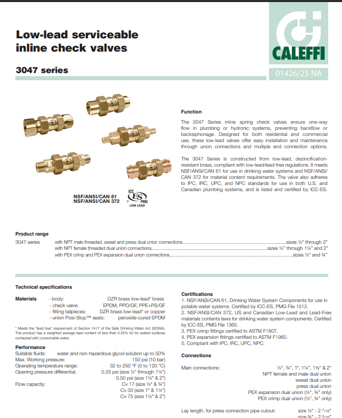
I'm thinking of getting Caleffi Union 304770A or the size up 304780A.
What's the minimum flow for that is acceptable?
Caleffi doesn't list that anywhere.
My understanding is that they may be noise and won't last as long if the low is too low.
0 -
I think you mentioned 180,000 net output for the boiler? So if you are working around a 20delta you would flow 18 gpm. A 1 or - 1/4" Caleffi will work for that gpm.
But that pump is capable of 40 gpm or more, so what gpm are you considering. If for some reason you run out that far, I'd go with a 1-1/2".
At 18 gpm you look for a valve with an 18 Cv
With a spring check designed for hydronic use the opening pressure differential sometimes called "pop psi" is the low end. So the 1 and 1-1/4 will fully open with a 1/2 psi differential, which that pump will certainly provide.
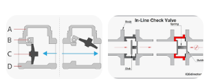
The low flow becomes an issue when swing checks are used in hydronics, at low flow, and with variable speed circulators, the gate may not get pushed open fully and causes chattering which will destroy the valve.
Here is a look at the difference between spring and swing checks.
MonoFlo/ diverter systems are a bit of an unique animal.
When you try to control then with TRVs or manual valve adjustment neither of the variable speed modes constant flow or constant pressure is ideal. Since a diverter tee is not exactly a parallel system. It's sort of a blend of series and parallel. So as you adjust one "assembly" you will effect all the others.
If one room or radiator is adjusted, even with a manual valve at the radiator, every other radiator will see or "feel" that change.
Let us know how the system behaves with the new circulator.
Siggy suggested this could be a case where a delta T circ may make sense, making it flow decision based on temperature drop across the system instead of pressure differential. As long as the boiler is not operating on ODR.
Bob "hot rod" Rohr
trainer for Caleffi NA
Living the hydronic dream0 -
0034e plus is only responsible for about 14GPM.
would the 33CV and 75CV versions of caleffi work well at that rate?
My understanding is that the spring type flow checks can be noisy and fail prematurely if the flow is insufficient to open them up enough.
The maximum i can push through that line with 0034e plus is about 22GPM (each monoflow rad seeds a fraction of this), i need to do this occasionally to bring the magnetite back to the Dirtmag at the boiler and clear up minor air locks. I don't want to put a restrictive flow check which will reduce the 22gpm further.
0 -
ALWAYS buy a valve as close to the Cv that you need. Especially for control valves. I'd consider a check a control valve.
A small amount of undersize is not generally an issue. a 16 Cv valve used for a 18 gpm flow just adds some, 1.27 psi pressure drop. This shows in those Excel examples I posted a few screens above.
A 1 cv valve with 10 gpm flow would probably let you know it is unhappy, velocity noise, possible cavitation, short life expectancy.
If it were just a ball valve used for shutoff, oversizing would not be such an issue. You could put a 1" ball valve on a 1/2 line as a shutoff without causing problems.
The biggest issue I see with pumps with internal checks is with even a small amout of air they bounce like crazy and eventually come apart. I have a video of that with some clear piping that allow you to see the check doing the mambo.
Bob "hot rod" Rohr
trainer for Caleffi NA
Living the hydronic dream0 -
It is spelled out. It needs 1/2 psi pressure differential to open. Doesn't matter is it is 15 or 50 gpm, the pressure differential is what pushes it open it open
You could hold it against your lips give it a puff and it will open, no gpm required. Assuming you have enough lung to exhaust .35- .50 psi?
Once again the Cv number is how you select valves. GPM at 1 psi pressure drop.
If you know your gpm number is 22 gpm, why would need a minimum gpm number?
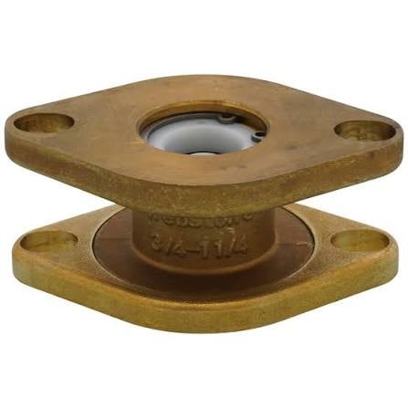
That valve you show also indicates 3/4-1-1/4.
15 gpm in a 3/4 copper is around 10 fps. , well beyond the typical 2-4 fps in hydronics.
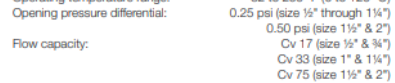
Your circ could rev down to under 5 gpm flow and it will develop enough delta P to open
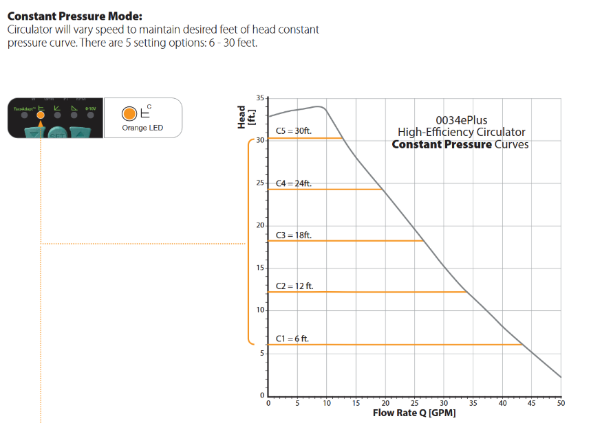
Perhaps some manufacturers put gpm range assuming the buyer doesn't know or understand Cv?
If I were a betting man, the check in the product you show is exactly the same as the Caleffi. Probably even the same brand.
Bob "hot rod" Rohr
trainer for Caleffi NA
Living the hydronic dream0




Categories
- All Categories
- 87.9K THE MAIN WALL
- 3.3K A-C, Heat Pumps & Refrigeration
- 60 Biomass
- 430 Carbon Monoxide Awareness
- 134 Chimneys & Flues
- 2.2K Domestic Hot Water
- 6K Gas Heating
- 124 Geothermal
- 170 Indoor-Air Quality
- 3.9K Oil Heating
- 80 Pipe Deterioration
- 1.1K Plumbing
- 6.7K Radiant Heating
- 397 Solar
- 16.1K Strictly Steam
- 3.5K Thermostats and Controls
- 56 Water Quality
- 51 Industry Classes
- 52 Job Opportunities
- 18 Recall Announcements