Welcome! Here are the website rules, as well as some tips for using this forum.
Click here to Find a Contractor in your area.
If our community has helped you, please consider making a contribution to support this website. Thanks!
Cast boiler buffer, DHW, piping schematic & parts list
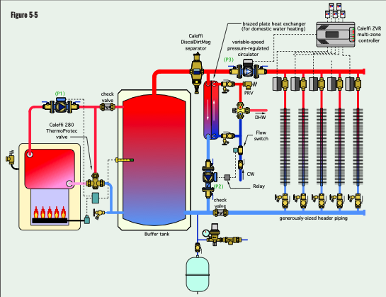
Here is a system I have done several times, including my own system with a wood fired boiler.
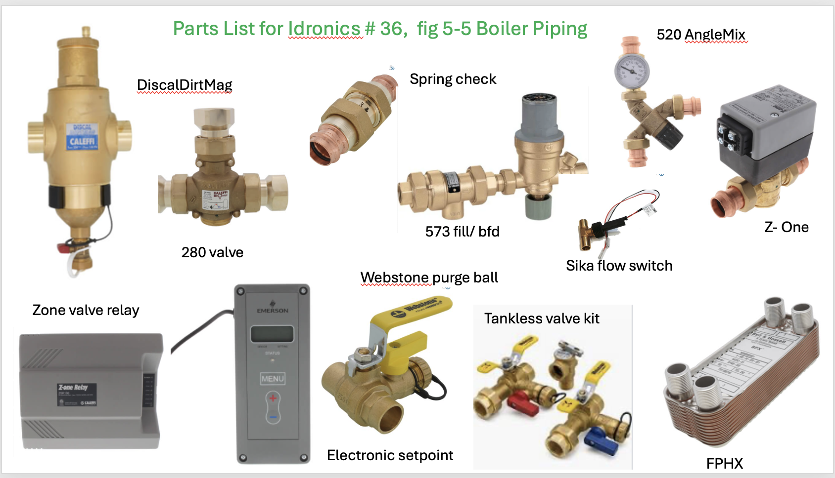
The parts list will give you an idea of many of the costs for piping.
A setpoint control runs the boiler, a 120- 160 or so range may be possible with the correct FPHX sized to the needs of the job.
Run the tank temperature as low as possible on design day, for example. The electronic setpoint controls are simple to adjust and you read tank temperature on their display. Sensor can go into well or push against the side of the tank under insulation.
The 280 protects the boiler return
The tank could be a basic insulated storage available from any WH manufacturer. Or a specific buffer tank from Boiler Buddy, Lochinvar, Zilmet, System 2000, Wessel, and most tank manufacturers. Most all tanks have 1.5- 2" foam insulation now to minimize loss.
A Tankless valve kit valve on the HX, B side.
A delta P circulator with zone valves. Multi speed circ for the boiler and HX for some flow adjustability.
One large Webstone purge valve, on the blue return pipe, is an option to purge all zones from a single valve.
If you know how many gpm you need for DHW, size the HX with help from a rep
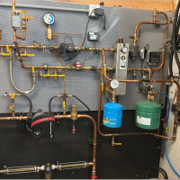
trainer for Caleffi NA
Living the hydronic dream
Comments
-
Nice! If I do so much woodworking in my shop, I’d have used cast iron boiler; likely Peerless.
Steve Minnich0 -
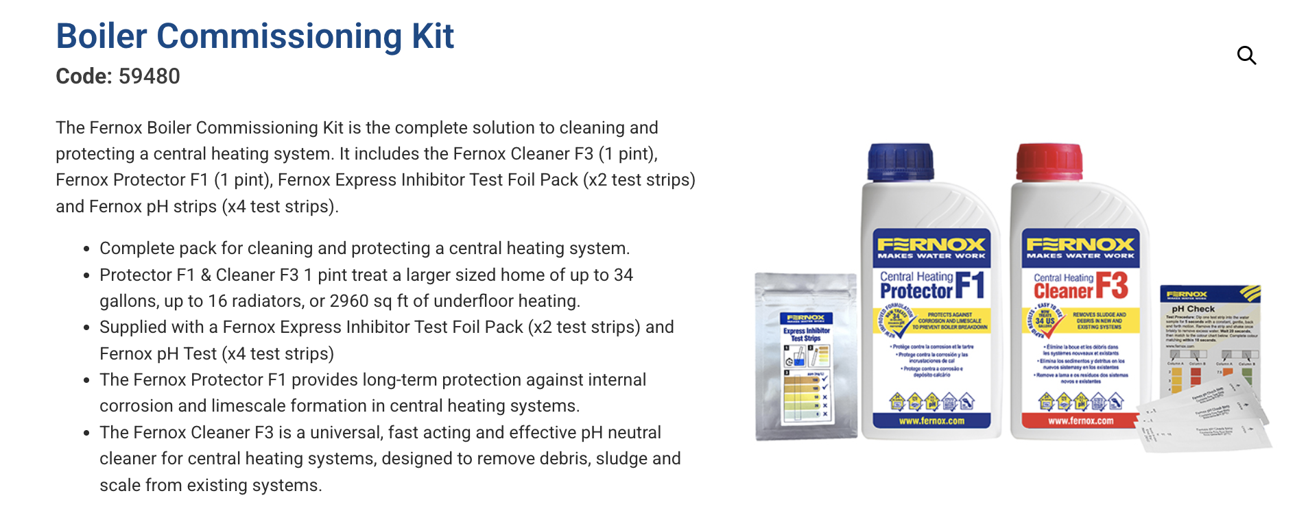
And this!
Bob "hot rod" Rohr
trainer for Caleffi NA
Living the hydronic dream0 -
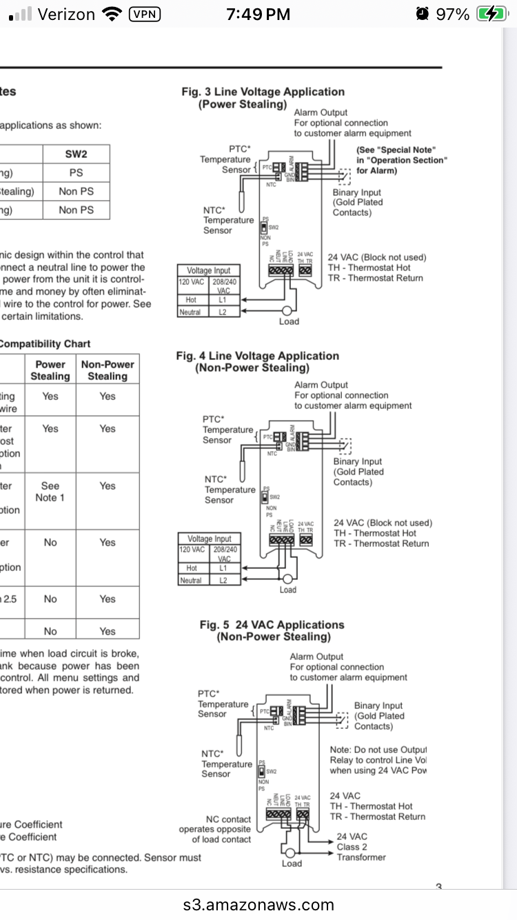
I’m struggling to understand the wiring of this. Sensor goes to the well. Binary Input would go to boiler TT? But how is P1 communicating with the set point control?
0 -
P1 is powered off the boiler pump relay.
Whenever the setpoint calls for tank heat, the boiler is enabled via TT.
The setpoint control needs power to operate. You can get either 24 or 120V. So wire that to any power source
Use a 120V and plug it into a receptacle with P3
The output contacts of the setpoint control are dry contacts, no power applied.
They “make” the TT which is powered by the boiler 24V transformer
P3 the system pump wires to a receptacle, powered all the time. It wakes up when a zone valve opens
A flow switch in the cold feed to the HX turns on P2
I used a Sika .50 gpm switch. Same switch used in combis and tankless water heaters
SupplyHouse has them under the LAARS brand name
Bob "hot rod" Rohr
trainer for Caleffi NA
Living the hydronic dream0 -
Ok. P1, P2, and P3 make sense. Set point power makes sense. Tank sensor makes sense. Communication from set point to boiler TT would have to come off the “TH” and “TH” from the set point control, correct?
the communication from set point control to boiler I’m missing.
0 -
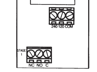
With this brand and model, you have 3 connections at the bottom.
NC normally closed
NO normally open
Common
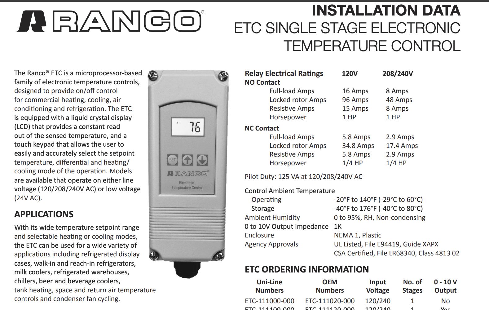
When the control is in heating mode common and NC are "made" , a closed contact, wire that to TT. So as temperature rises, that contact (Com and NC) will open and turn off the boiler. Thermostst wire is fine, it's 24VAC.
The control is really just a switch, that happens to be activated by a temperature signal.
Many brands of this type of control Honeywell, Johnson Control, Ranco, Penn, etc.
This brand and model has a easy to follow instruction.
If you use the FPHX, then the tank needs to stay hot 24/7
The temperature you end up running will depend on the HX you use and how much DHW you want to provide.
Obviously the higher you maintain the tank, the greater the DHW production.
If efficiency is the goal, run the boiler as low as possible to supply DHW. Maybe that is 160? Or 150?
You can calculate that knowing how much DHW you want and the HX sizing program. Or trial and error the settings.
The MOST amount of DHW will depend on the boiler size. With 77,000 you could get close to 2 gpm continously. And that depends on how cold the incoming water is and the final temperature you want.
98- 105 is typical shower temperature. Since you are not storing more that a quart in the HX, legionella concerns are not a concern as a tank full of tepid water.
If you chose to produce dhw at 105- 110, use the temperature boost function on the dishwasher.
With a 50 gallon tank, you have some dump capacity until the tank temperature drops. This is true whether you use tank capacity for DHW, or the FPHX uses the tank capacity as the heat source. Or a reverse indirect.
This whole package is adjustable to what works for you. There is no exact setting that you build to. At days end you want a warm home on the coldest day, and you want adequate DHW.
 Bob "hot rod" Rohr
trainer for Caleffi NA
Living the hydronic dream 1
1 -
do you have any preferences on the relay for P2?
0 -
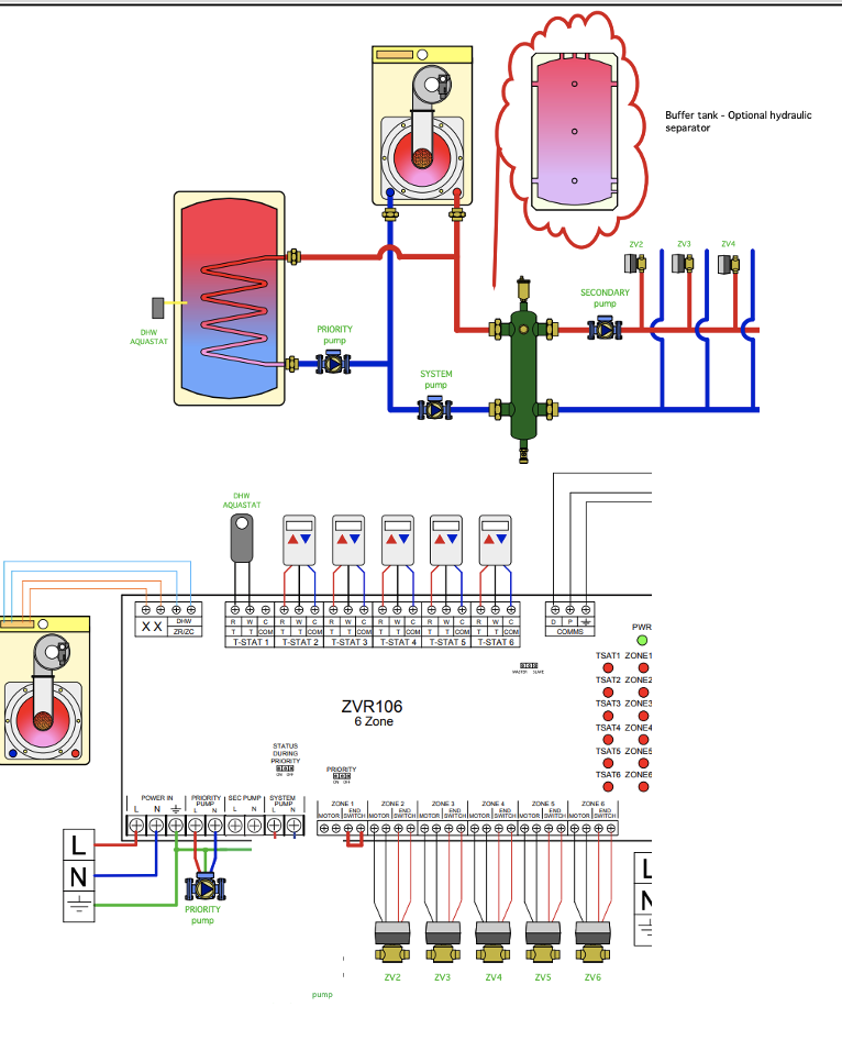
This isn't your exact piping, but the control logic matches what you want to do.
Use a relay in the Calefi zone valve relay box for the flow switch/ pump interface
If you have 3 zone valves buy a 5 or 6 relay box
3 zone valves
1 for the flow switch
1 or 2 spare for any future zones or a backup if a relay fails
Wires like this:
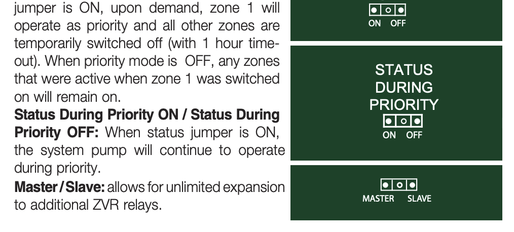
Flow switch (shown as DHW aquastat) wires to the R W, zone 1 at top. Zone 1 is always priority zone on the Caleffi relays
jumper end switch on zone one, at bottom.
Put box in priority mode, on the jumper at the bottom of the circuit board.
HX pump wires to priority pump connection at bottom 120V
Now when the DHW calls, all zone valves close. Full boiler output is available for DHW production
System Pump in this drawing is your boiler pump, wired to the boiler pump relay, not the relay box
Secondary Pump is your Grundfos Alpha zone valve pump which I would just power all the time.
Ignore the blue wires labled DHW from relay to boiler, the setpoint control is handling this function.
The Grundfos Alpha 15-58 has a built in exercise function so every 72 hours, if there has not been a heat call, it will run, for a minute, if you keep it plugged in. This is to prevent seizing over the non use season. It runs about 7W in idle mode, no big deal.
If you want to use a 24VAC setpoint control, run 3 conductors from the relay box to the control R & W gives you 24v to power the setpoint control.
Bob "hot rod" Rohr
trainer for Caleffi NA
Living the hydronic dream0 -
why would you want the zone pump in constant power? Aren’t you dead heading the pump against closed zone valves if there is no call for heat?
Also, you are running 3 conductors to the set point control for power. How does the communication for the tank actually work/ when would the low voltage run? In series from control logic to boiler TT?0 -
The delta P circ are designed to be powered all the time. They were originally designed for thermostatic radiator valves, which have no power or switch to fire the pump. TRVs open, pump revs up to required rpm/gpm.
At no zone valve open condition, the pump is spinning ever so slow. It needs to be moving so that when a ZV opens it senses a ∆P and revs. A second valve opens it speeds up more. Think of it as a pump on cruise control.
Down load the Alpha installation manual for more detail on settings.
Idronic 16 explains in more detail the ∆P circulator operation. The cover pic shows a ∆P circ doing its thing.
When it is powered all the time the exercise function can be used.
If powering the pump continuously freaks you out, it could be wired through the relay box and only run when a ZV opens. But you lose the ability to use exercise. The "system pump" relay connection in the relay box.
Trust me, the pump can be powered continuously. I've been running Alphas like this since they came out, 10- 15 years ago or more.
So control logic:
Thermostats wire to relay box 2,3, & 4 connections Run 4 conductor wire to t-stats if you plan on using electronic power stealing stats.
Zone valves wire to relay box 2, 3 & 4 connections (4 conductor wire)
XX on relay box, upper right goes to boiler TT. Boiler and pump enable when any zone opens. So boiler pump wires to boiler relay 120V
That covers the heat control logic.
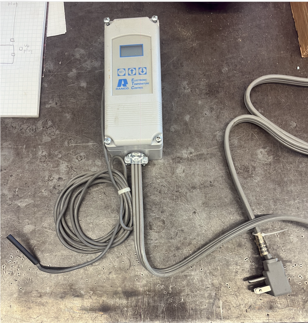
For DHW you need a setpoint control, sensor on or in the tank
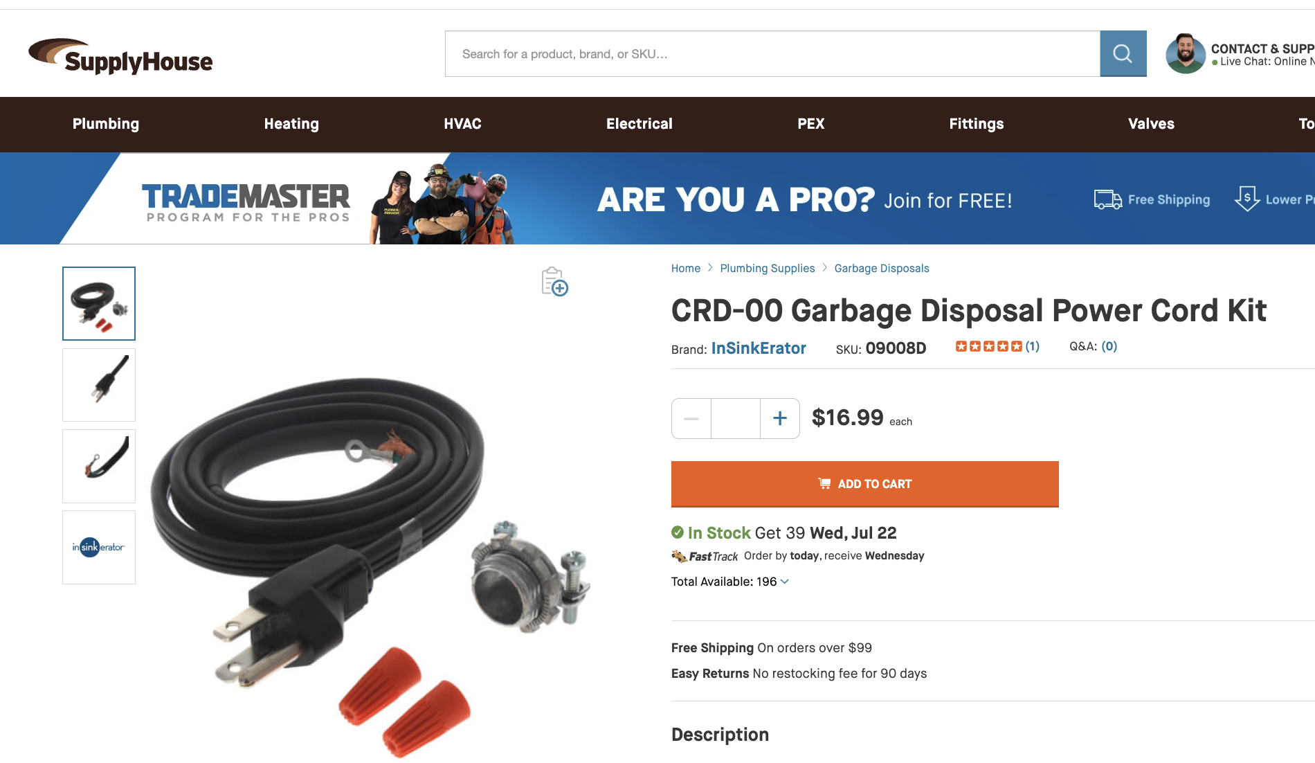
Power the setpoint control, either a 120V plugged into the wall receptacle. Buy the 120V control and cord at SupplyHouse.
OR a 24V version powered from the relay box transformer, your choice. It needs to be powered continuously.
The setpoint switch, regardless of which version you use, NC & C wire to zone 1 on top of the relay. Jumper the end switch on zone 1, at bottom
When this zone 1 (DHW) is enabled the boiler is again switched on via XX. If you enable "priority" on the relay box, heat zones drop off when DHW calls. With your oversized boiler maybe you do not need to prioritize DHW, maybe it can handle both at the same time.
The Caleffi relay, when in priority, will drop that DHW call after an hour, so you don't lose heat for more than 1 hour.However if you want continuous DHW why not use priority? Try it both ways to see what suits your needs.
If you say nice things to @EdTheHeaterMan maybe he will draw a nice wiring schematic.
Most any HVAC tech or plumber with hydronic experience could wire this with the info and pics provided in this post.
Consider downloading the manuals for all the compoents to read up on how they install, adjust, etc. Before you buy.
 Bob "hot rod" Rohr
trainer for Caleffi NA
Living the hydronic dream0 -
yeah, I’m not doubting you about the pump at all. Idk if it has been a wives tale or not, but I was always told that you don’t want to dead head pumps. Water can’t compress and you’ll overheat the pump if water is not moving (that’s already in a heating system).
As far as the questions, I’ve just been limited in the hydronics. I can wire a cast iron with indirect like no other if that helps?? My instruction has been limited to the knowledge of the guy I worked with for X years, and any personal research I have done on my own. I’m not trying to just figure out how to do something, I’m trying to understand why.
Being honest. The low voltage wiring makes my head spin. The hydronics side I feel like I have an intermediate grasp. Most of the stuff I read on here makes sense. I’ve been introduced to things I didn’t even know existed because of this forum. It’s the how do I make things do what I want them to do, when I want them to that I struggle with.

 2
2 -
let me re phrase. The dead heading could cause cavitation of the pump.
0 -
also, I don’t think I need a sketch. What you explained makes sense.
0 -
Depending on which part number you order some Grundfos Alpha ship with a power cords. They would not do this if the pump could not be powered?
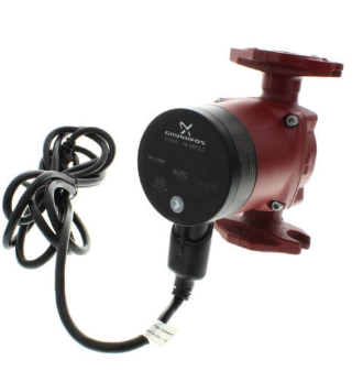
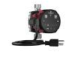
The pump learns the hydraulics of your system. When all zones close it ramps down to 0 flow. It is not deadheading.
Go here and watch the various modules to learn more from the manufacturer.
If you load the GO app on your phone you can watch everything the pump is doing, operation mode, gpm, rpm, flow, temperature, etc. Plus you can change settings from your phone.
The Caleffi relays have self resetting fuses, so if you screw up the wiring you will not damage the board. within reason :)
The120V and 24V wiring needs to be correct, on the correct terminals.
Bob "hot rod" Rohr
trainer for Caleffi NA
Living the hydronic dream0 -
If you ever do need a wiring schematic where you need to put several components together I would be glad to help with that. I will take all the components wiring diagrams from each device from different manufacturers and place the interconnecting wires on that page so it all makes sense. You tell me what you want the stuff to do and I will make the wires do it. You can look at some of my diagrams here:
Edward Young Retired
After you make that expensive repair and you still have the same problem, What will you check next?
0 -
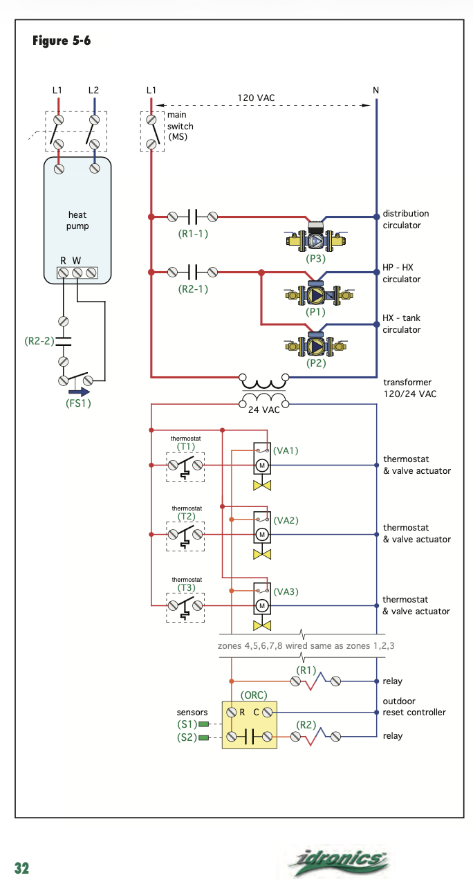
it's good to have the system documented, for the next person that may need to troubleshoot or uderstand the logic.
An essay, piping and wiring schematic in a folder near the boiler.
 Bob "hot rod" Rohr
trainer for Caleffi NA
Living the hydronic dream1 -
This is an incredible forum you guys are apart of. Thank you both for the help.
0


Categories
- All Categories
- 87.8K THE MAIN WALL
- 3.3K A-C, Heat Pumps & Refrigeration
- 60 Biomass
- 430 Carbon Monoxide Awareness
- 133 Chimneys & Flues
- 2.2K Domestic Hot Water
- 6K Gas Heating
- 124 Geothermal
- 170 Indoor-Air Quality
- 3.9K Oil Heating
- 79 Pipe Deterioration
- 1.1K Plumbing
- 6.7K Radiant Heating
- 397 Solar
- 16.1K Strictly Steam
- 3.5K Thermostats and Controls
- 56 Water Quality
- 51 Industry Classes
- 51 Job Opportunities
- 18 Recall Announcements